US480415A - Heel-loading machine - Google Patents
Heel-loading machine Download PDFInfo
- Publication number
- US480415A US480415A US480415DA US480415A US 480415 A US480415 A US 480415A US 480415D A US480415D A US 480415DA US 480415 A US480415 A US 480415A
- Authority
- US
- United States
- Prior art keywords
- heel
- cam
- head
- templet
- nail
- Prior art date
- Legal status (The legal status is an assumption and is not a legal conclusion. Google has not performed a legal analysis and makes no representation as to the accuracy of the status listed.)
- Expired - Lifetime
Links
- 238000010276 construction Methods 0.000 description 3
- 239000007787 solid Substances 0.000 description 3
- 230000008520 organization Effects 0.000 description 2
- 239000000126 substance Substances 0.000 description 2
- 239000000969 carrier Substances 0.000 description 1
- 150000001768 cations Chemical class 0.000 description 1
- 150000001875 compounds Chemical class 0.000 description 1
- 230000006835 compression Effects 0.000 description 1
- 238000007906 compression Methods 0.000 description 1
- 239000002184 metal Substances 0.000 description 1
Images




Classifications
-
- A—HUMAN NECESSITIES
- A43—FOOTWEAR
- A43D—MACHINES, TOOLS, EQUIPMENT OR METHODS FOR MANUFACTURING OR REPAIRING FOOTWEAR
- A43D33/00—Machines for assembling lifts for heels
- A43D33/04—Nailing machines for building the heels from lifts
Definitions
- the invention relatesto a machine for antomatically loading or loading and compressing heel-blanks; also, to various details of organization and construction of the'mechanism employed.
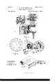
- Figure 1 is a View in front'elevation of a machine having the features of my invention, the nail-supplying devices not being shown.
- Fig.2 is a view in vertical central section thereof, taken from front to rear of the machine,without the nailsupplying devices.
- Fig. 3 is a view in plan of the cam for operating the nail-carrier plate.
- Fig. at is a View in plan of the support for the heel.
- Fig. 5 is a detail view illustrating the mechanism for automatically feeding heelblanks from a stack to a position beneath the templet.
- Fig. 6 is a view in rear elevation of the devices for automatically turning the rotary head.
- Fig. 1 is a View in front'elevation of a machine having the features of my invention, the nail-supplying devices not being shown.
- Fig.2 is a view in vertical central section thereof, taken from front to rear of the machine,without the nailsupplying devices.
- Fig. 3 is a view in plan of the cam for operating the nail-car
- FIG. 7 is a view of the rotary head, also showing heel-blank ejectors, to which reference is hereinafter made.
- Fig. 8 is a View illustrating the relation which the automatic nail-feedin g devices bear to the nailingmachine, and also a peculiar form of nail-feeding plateand mechanism foroperatingit.
- Fig. 9 is a view in plan of the nail-feeding or carrierplate represented in Fig. 8 and the nail-carrier supported thereby.
- Fig. 10 is a View below the dotted line 00 0c of Fig. 8, illustrating the mechanism for rotating the nail-carrier represented in that figure and in Fig. 9.
- Fig. 10 is a View below the dotted line 00 0c of Fig. 8, illustrating the mechanism for rotating the nail-carrier represented in that figure and in Fig. 9.
- Fig. 10 is a View below the dotted line 00 0c of Fig. 8, illustrating the mechanism for rotating the nail-carrier represented in that
- FIG. 11 is a view of a removable solid die, which is used when the heel-blanks are to be compressed laterally,as well as vertically.
- Fig. 12 is a View in vertical section taken through the nailsupplying devices.
- Figs. 13, 14,15, and 16 are detail views of the mechanism for turning the carrier-plate represented in Fig. 8.
- Fig. 17 is a View of a loaded heel-blank.
- Figs. 18 to 20, inclusive, are detail views.
- A represents the cross-head. It supports a revolving head a, having the arms a' a a a
- the arm a supports a gang or group of awls a
- the arm 0 which is the next in order, supports a gang or group of drivers a
- the arm a supports a second gang or group of awls a which are of the same size and of the same arrangement as the gang or group of awls (L
- the arm a supports a second group of drivers a which are of the same size and order of arrangement as the gang 0..
- the cross-head A is reciprocated by means of the crank-pins 13, formed on the gears 19 and the connecting pitmen or rods 1).
- the revolving head a is automatically rotated upon the re oiprocation of the cross-head by means of mechanism substantially like that described in the application of O. 0.
- the mechanism further comprises a plate 0 having the stationary cam or guide grooves c c 0 .
- Each of the cam-grooves c c is connected with the central cam-groove 0 near the upper end of the central cam-groove, and these grooves are arranged to permit the rotary movement of the cam-pins.
- the rotary movement is communicated to the disk by means of the inclined or curved surfaces 0 0 .
- a cam-pin 0 comes in contact with the inclined surface 0, which is made up in part of the surface (2 of the stationary portion 0 of the plate and in part of the surface 0 of the latch-block o this latch-block being movable horizontally out, of and into the groove 0 by the passage of a cam-pin by it and the force of a spring acting behind it to push it into the groove, and when in the groove it serves as a stop in preventing the cam-pin from returning from the straight groove into the curved groove, by which it entered the straight groove, its edge acting as a guide in causing the cam-pin to move upon the upward movement of the cross-head along the turning surface 0.
- the latch-block c is made as a solid block of metal having the inclined surface 0 and a stud c ,and it is movable in a hole 0, out in the plate 0 and is to its original position.
- the guiding-surface c is formed by the surface 0 of the stationary section 0 of the plate and the surface 0 of the movable block 0
- the movable block is mounted upon the plate and made movable in relation to the groove in the same manner as the block 0 and has an inclined surface 0 with which the ends of the campins are successively brought in con tact upon the upward movement of the cross-head, the surface 0 of the block forming both a stop and a guide. This mechanism causes the rotary head to make a complete revolution for every four reciprocations of the cross-head.
- D is the templet. It is removable from the upper table at of the machine which supports it; but it is preferably not provided with a vertical or yielding movement. Ithas the holes d, in which the awls and drivers are reciprocatcd.
- E is a nail-carrier. It has the holes 6 for receiving the nails, and in Fig. 2 it is represented as moved automatically from the nailsnpplying devices F to the templet D by means of a cam-groove c and the cam-disk e on the vertical shaft 6 and a slide-plate 6 to which the nail-carrier is secured and which has a cam-pin e entering the cam-groove.
- the cam-groove is constructed to provide the nail-carrier E with two feeding movements in relation to the templet D for every full revolution of the rotary headthat is, it is in its back position receiving nails duringthe reciprocation of the first gang of awls, is moved forward to deliver the nails upon the lifting of the cross-head and before the reciprocation of the first gang of drivers, remains in position over the templet during the operation of the first gang of drivers, is withdrawn during the upward movement of the first gang of drivers to receive the second gang or group of nails from the nail-feeding devices and during the reciprocation of the second group of awls, and is moved forward again to deliver a second group of nails to the holes of the templet D in season to receive the second group of drivers.
- the shaft 6 preferably is rotated by means of the worm-wheel e and the worm e upon the pulley-shaft F, and the pulley-shaft is connected with the gears 1), bearing the crank-pins B, by means of pinions f.
- G is the heel-support or pressure-block. It is removably secured to the upper end g of the pressure-spindle g, the pressure-spindle being supported by the post 9 extending upward from the middle table 9 and it is provided with a vertical movement by means of the pressure-head 9, having a vertical movement in the post 9 extending from the frame, as shown, or upward from the lower table 9 and the edge cam 9 upon the camshaft
- This cam-shaft has'suitable bearings and is connected with the shaft g", to which the gears 19 are attached by means of pinions g on the shaft 9 and gears g on the shaft 9 which mesh with the pinion 9
- the cam 9 is constructed or shaped to provide the pressure-head with these movements in relation to the templet in every revolution: first, a quick upward movement to compress the heel-blank against the under surface of the templet; second, a period of rest, or practically of rest, during the driving of the nails; third, a quick release of the heelblank to permit its removal and the feeding of another heel-blank; fourth, a second upward compressing movement to compress a second heel; fifth, a period of rest during the driving of the nails into the second heel, and, sixth, a downward releasing movement.
- an adjustable bearing-block g ,11pon which the lower end of the spindle g rests, and which is made with a screw to fit the screw-thread in the end of the head, whereby it is made vertically adjustable in relation thereto.
- heel-blank-feeding devices substantially like those shown and described in the said Small application and comprising, in substance, a heel-blank slide-plate H, operated by a cam h on the cam-shaft e and lever 71/ and bearing the heel-blank-holding devices It h and the heels are fed to these holding devices by a slide h, which removes them one by one from a stack h to a lifting-diaphragm h, which lifts them into position to be grasped by the heel-grasping devices, one of the grasping devices being moved or opened automatically bya projection on the slideh to permit the lifting-diaphragm to act to place the heel.
- the slide 71. is operated by means of the said cam h, a connecting-lever, and a link.
- This mechanism or the equivalent for it has already been described in the said Small appli cation, and also in my pending application filed April 19, 1887, and need not further be described here. It is only necessary to say that the cam is constructed to move the heelcarrier to feed a heel-blankupon the upward movement of each gang of drivers into position and to withdraw the carrier as soon as the heel-blank is compressed against the templet and during the upward movement of the awls, in order that it may receive another heel-blank from the stack.
- Each gang of drivers is made as to length to partly drive the nail into the heel-blank, a loaded heel-blank being a heel in which the attaching-nails are partially driven and which is adapted to be subsequently attached to the soles of the boot or shoe byindependent naildriving devices.
- I mount in the arms a a of the rotary head independent releasing-pins M, each of which is movable therein, a strong spring on being placed back of each to force it outward.
- Each pin extends from its respective arm farther than the drivers and is adapted to enter a hole in the nail-carrier and templet, and in the operation of the machine it is brought into contact with the uppersurface of the heel-blank during the downward movement of the rotary head and rests there during the driving of the nails; but upon the upward movement of the head, the pressurehead being immediately released, the pin is forced downward by the spring sufficient to throw or push the heel-blank from the templet, causing it to follow the heel-support and freeing the nails from the templet.
- these push-pins can be positively operated, if desired.
- the nail-supplying devices F preferably are like those described in my application for Letters Patent of the United States filed March 31, 1888, Serial No. 269,055, and which comprise a distributor N, the rolls n 'n' n a carrying groups of nail pointing and severing devices, the feed-rolls n n n, and m and their operating mechanism, the machine being organized to make a gang or group of nails simultaneously from the ends of as many wires as there are nails made, so that one revolution of the machine makes the entire number of nails used.
- I am en-- abledto supply nails as rapidly as they can be fed.
- the start and stop motion mechanism (not shown) of the nail making devices' is similar to that described in my patent, No. 317,199, the start-motion mechanism being automatically operated by the nail-driving devices to cause the nail-making machine to make one revolution within every two reciprocations of the cross-head.
- the machine as thus organized is adapted to work continuously-that is, to automatically feed the heel-blank to the compressing, pricking, and loading devices, to automatically consolidate and prick it, to automatically make and deliver the nails to the blank, and to automatically drive them into the heelblankto load it, and to free the loaded heelblank continuously without stopping the machine.
- the slide-plate Il may be mounted upon the plate g.
- a reciprocating nail-carrier E there may be used a rotary plate 3, carrying a series of nail-carriers s, which are turned or advanced in successive order from the nailsupplying mechanism F to the templet, in which event a carrier is always in position over the templet, and the awls are reciprocated through the holes of the carrier, a nailcarrier after delivering its nails to the holes of the templet remaining in position during the reciprocation of the next gang of awls, when the plate sis turned to bring the nextcarrier, with a load of nails, into position over the templet.
- This rotary movement of the plate 8 also brings each nail-carrier in successive order into position to receive a gang or group of nails from the nail-supplying devices.
- the plate may be intermittently rotated by hand or automatically, and in Figs. 8, 10, 13, 14, 15, and 16 I have represented devices for providing it with automatic rotation by means of mechanism similar to that for rotating the head, the plate 8 having a shaft 5 provided with a disk 3 carrying cam-pins s and a slide cam-plate 3 the equivalent of the stationary cam-plate c
- This slide cam-plate s is represented in Figs. 8, 10, 15, and 16,aud it is provided with a horizontal back-and-forth movement at suitable intervals by the cam s on the vertical shaft 6
- This slide-plate has the two latches s7 each of which is movable vertically downward from the plate in opposition to a spring 3 and each of which has an inclined surface 8 ending in a shoulder s.
- the shoulder s of the latch s is curved and forms, in connection with the curved edge s of the section .9 of the plate, a cam or guide for turning the disk 5 and consequently the rotary plate 8 upon the movement of the cam-plate s away from the cam s by means of one of the cam-pins 8 against which it operates as it is moved.
- the nailmaking devices may be started by hand and the nail-carrier moved by hand instead of starting it automatically and moving it automatically.
- a heel-loading machine the combination of a cross-head, a rotary head supported thereby and carrying two gangs or groups of awls and two gangs or groups of drivers in the order named, each of the two groups of awls and two groups of drivers being of the same arrangement and adapted for use with the same templet, with the said single templet having holes (1' and a heel-support or former having independent vertically and united horizontally operating adjusting devices in connection therewith, and a single nail-carrierE to feed nails in successive order for each group of drivers, substantially as described.
- a heel-loading machine the combination of a cross-head, a rotary head supported thereby and carrying two gangs or groups of awls and two gangs or groups of drivers in the order specified, each of the two groups of awls and two groups of drivers being of the same arrangement and adapted for use with the same templet, with the said single templet having holes d and a heel-support havingindependent vertically and united horizontally operating adjusting devices in connection therewith, and the heel side compressing or forming die, substantially as described.
Landscapes
- Portable Nailing Machines And Staplers (AREA)
Description
(No Model.) 7 Sheets-Sheet 1,
- E. F. RAYMOND, 2d.
HEEL LOADING MACHINE.
No. 480,415. Patented Aug. 9, 1892.
f m WITNEEEEE- mm a |NVENTIIIFL ?l -m 5*! 1 5? QWMQM J 6% M :aitsf l6 WW 7 Sheets-Sheet 2.
(No Model.)
" P. P. RAYMOND, 2d.
HEEL LOADING MACHINE-V Patented Aug. 9, 1892.
I II I 00/ #(l ilziyy 2 7 9 9 .9 9' 95 7 I/ 7 0 9 9 e g (R0 Model.) 7 7 Sheets-Sheet 3.
- 1?. P. RAYMOND,,2(1. HEEL LOADING MACHINE.
No. 480,415. Patented Aug. 9, 1892.
WITNE55E5 m Inuat: 00.. nam'rm, u. c.
(No Model) 7 Sheefs-Sheet 4.
F. F. RAYMOND, 2d.
HEEL LOADING MACHINE.
No. 480,416. Patented Aug. 9, 1892.
\A/lTNEEEEE 5 INVENTEIR m: nanms PETERS 4:04, PHOTD-UTHO WlSHl-l eeeeeee c.
(No Model.)
-' 7 Sheets-Sheet 5. P. F. RAYMOND, 2d.
HEEL LOADING MACHINE.
Patented Aug. 9, 1892.
(No Model.) 7 Sheets-Sheet 6 P. F. RAYMOND, 2d. HEEL LOADING MACHINE.
o. 480,415. Patented Aug. 9, 1892.
(No Model.)- 7Sheets-Sheet 7.
. RAYMOND, 2d.
LOADING MACHINE.
No. 480,415. Patented Aug. 9, 1892.
' ZII \A/IWESEEi 5 .|N\/EN E1|= NITED STATES PATENT FFlCE.
FREEBORN F. RAYMOND, 2D, OF NEWVTON, MASSACHUSETTS.
HEEL-LOADING MACHINE.
SPECIFICATION forming part of Letters Patent No. 480,415, dated August 9, 1892.
To all whom it ntay concern:
Be it known that I, FREEBORN F. RAYMOND, 2d, a citizen of the United States, residing at Newton, in the county of Middlesex and State of llfiassachusetts, have invented a new and useful Improvement in Heel Loading Machines, of which the following is a full, clear, and exact description, reference being had to the accompanying drawings, forming a part of this specification, in explaining its nature.
The invention relatesto a machine for antomatically loading or loading and compressing heel-blanks; also, to various details of organization and construction of the'mechanism employed.
Referring to the drawings, Figure 1 isa View in front'elevation of a machine having the features of my invention, the nail-supplying devices not being shown. Fig.2 is a view in vertical central section thereof, taken from front to rear of the machine,without the nailsupplying devices. Fig. 3 is a view in plan of the cam for operating the nail-carrier plate. Fig. at is a View in plan of the support for the heel. Fig. 5 is a detail view illustrating the mechanism for automatically feeding heelblanks from a stack to a position beneath the templet. Fig. 6 is a view in rear elevation of the devices for automatically turning the rotary head. Fig. 7 is a view of the rotary head, also showing heel-blank ejectors, to which reference is hereinafter made. Fig. 8 is a View illustrating the relation which the automatic nail-feedin g devices bear to the nailingmachine, and also a peculiar form of nail-feeding plateand mechanism foroperatingit. Fig. 9 is a view in plan of the nail-feeding or carrierplate represented in Fig. 8 and the nail-carrier supported thereby. Fig. 10 is a View below the dotted line 00 0c of Fig. 8, illustrating the mechanism for rotating the nail-carrier represented in that figure and in Fig. 9. Fig. 11 is a view of a removable solid die, which is used when the heel-blanks are to be compressed laterally,as well as vertically. Fig. 12 is a View in vertical section taken through the nailsupplying devices. Figs. 13, 14,15, and 16 are detail views of the mechanism for turning the carrier-plate represented in Fig. 8. Fig. 17 is a View of a loaded heel-blank. Figs. 18 to 20, inclusive, are detail views.
A represents the cross-head. It supports a revolving head a, having the arms a' a a a The arm a supports a gang or group of awls a The arm 0, which is the next in order, supports a gang or group of drivers a The arm a supports a second gang or group of awls a which are of the same size and of the same arrangement as the gang or group of awls (L The arm a supports a second group of drivers a which are of the same size and order of arrangement as the gang 0.. The cross-head A is reciprocated by means of the crank-pins 13, formed on the gears 19 and the connecting pitmen or rods 1). The revolving head a is automatically rotated upon the re oiprocation of the cross-head by means of mechanism substantially like that described in the application of O. 0. Small forapatent, filed April 19, 1888, and which in substance comprises automatic rotating mechanism,
which consists, in brief, of a disk 0, attached to the shaft 0 of the rotary head, which disk carries four cam-pins 0', extending from the face thereof and near its edge, and the mechanism further comprises a plate 0 having the stationary cam or guide grooves c c 0 Each of the cam-grooves c c is connected with the central cam-groove 0 near the upper end of the central cam-groove, and these grooves are arranged to permit the rotary movement of the cam-pins. The rotary movement is communicated to the disk by means of the inclined or curved surfaces 0 0 Upon the upward movement of the cross-head a cam-pin 0 comes in contact with the inclined surface 0, which is made up in part of the surface (2 of the stationary portion 0 of the plate and in part of the surface 0 of the latch-block o this latch-block being movable horizontally out, of and into the groove 0 by the passage of a cam-pin by it and the force of a spring acting behind it to push it into the groove, and when in the groove it serves as a stop in preventing the cam-pin from returning from the straight groove into the curved groove, by which it entered the straight groove, its edge acting as a guide in causing the cam-pin to move upon the upward movement of the cross-head along the turning surface 0. The latch-block c is made as a solid block of metal having the inclined surface 0 and a stud c ,and it is movable in a hole 0, out in the plate 0 and is to its original position.
held by the plate and a boss 0, cast thereon, a spring serving to automatically return it The guiding-surface c is formed by the surface 0 of the stationary section 0 of the plate and the surface 0 of the movable block 0 The movable block is mounted upon the plate and made movable in relation to the groove in the same manner as the block 0 and has an inclined surface 0 with which the ends of the campins are successively brought in con tact upon the upward movement of the cross-head, the surface 0 of the block forming both a stop and a guide. This mechanism causes the rotary head to make a complete revolution for every four reciprocations of the cross-head.
D is the templet. It is removable from the upper table at of the machine which supports it; but it is preferably not provided with a vertical or yielding movement. Ithas the holes d, in which the awls and drivers are reciprocatcd.
E is a nail-carrier. It has the holes 6 for receiving the nails, and in Fig. 2 it is represented as moved automatically from the nailsnpplying devices F to the templet D by means of a cam-groove c and the cam-disk e on the vertical shaft 6 and a slide-plate 6 to which the nail-carrier is secured and which has a cam-pin e entering the cam-groove. The cam-groove is constructed to provide the nail-carrier E with two feeding movements in relation to the templet D for every full revolution of the rotary headthat is, it is in its back position receiving nails duringthe reciprocation of the first gang of awls, is moved forward to deliver the nails upon the lifting of the cross-head and before the reciprocation of the first gang of drivers, remains in position over the templet during the operation of the first gang of drivers, is withdrawn during the upward movement of the first gang of drivers to receive the second gang or group of nails from the nail-feeding devices and during the reciprocation of the second group of awls, and is moved forward again to deliver a second group of nails to the holes of the templet D in season to receive the second group of drivers. The shaft 6 preferably is rotated by means of the worm-wheel e and the worm e upon the pulley-shaft F, and the pulley-shaft is connected with the gears 1), bearing the crank-pins B, by means of pinions f.
G is the heel-support or pressure-block. It is removably secured to the upper end g of the pressure-spindle g, the pressure-spindle being supported by the post 9 extending upward from the middle table 9 and it is provided with a vertical movement by means of the pressure-head 9, having a vertical movement in the post 9 extending from the frame, as shown, or upward from the lower table 9 and the edge cam 9 upon the camshaft This cam-shaft has'suitable bearings and is connected with the shaft g", to which the gears 19 are attached by means of pinions g on the shaft 9 and gears g on the shaft 9 which mesh with the pinion 9 There is an antifriction roll 9 on the lower end of the pressure-head g to bear upon the edge of the cam. The cam 9 is constructed or shaped to provide the pressure-head with these movements in relation to the templet in every revolution: first, a quick upward movement to compress the heel-blank against the under surface of the templet; second, a period of rest, or practically of rest, during the driving of the nails; third, a quick release of the heelblank to permit its removal and the feeding of another heel-blank; fourth, a second upward compressing movement to compress a second heel; fifth, a period of rest during the driving of the nails into the second heel, and, sixth, a downward releasing movement.
There is attached to the upper end of the head g an adjustable bearing-block g ,11pon which the lower end of the spindle g rests, and which is made with a screw to fit the screw-thread in the end of the head, whereby it is made vertically adjustable in relation thereto. \Vhen the heel-blank is not sidecompressed in a die, the heel-blanks are fed automatically into position beneath the templet by heel-blank-feeding devices, substantially like those shown and described in the said Small application and comprising, in substance, a heel-blank slide-plate H, operated by a cam h on the cam-shaft e and lever 71/ and bearing the heel-blank-holding devices It h and the heels are fed to these holding devices by a slide h, which removes them one by one from a stack h to a lifting-diaphragm h, which lifts them into position to be grasped by the heel-grasping devices, one of the grasping devices being moved or opened automatically bya projection on the slideh to permit the lifting-diaphragm to act to place the heel. The slide 71. is operated by means of the said cam h, a connecting-lever, and a link. This mechanism or the equivalent for it has already been described in the said Small appli cation, and also in my pending application filed April 19, 1887, and need not further be described here. It is only necessary to say that the cam is constructed to move the heelcarrier to feed a heel-blankupon the upward movement of each gang of drivers into position and to withdraw the carrier as soon as the heel-blank is compressed against the templet and during the upward movement of the awls, in order that it may receive another heel-blank from the stack.
Each gang of drivers is made as to length to partly drive the nail into the heel-blank, a loaded heel-blank being a heel in which the attaching-nails are partially driven and which is adapted to be subsequently attached to the soles of the boot or shoe byindependent naildriving devices. To move or free the loaded heel-blank from the templet afterthe driving of the nails, I mount in the arms a a of the rotary head independent releasing-pins M, each of which is movable therein, a strong spring on being placed back of each to force it outward. Each pin extends from its respective arm farther than the drivers and is adapted to enter a hole in the nail-carrier and templet, and in the operation of the machine it is brought into contact with the uppersurface of the heel-blank during the downward movement of the rotary head and rests there during the driving of the nails; but upon the upward movement of the head, the pressurehead being immediately released, the pin is forced downward by the spring sufficient to throw or push the heel-blank from the templet, causing it to follow the heel-support and freeing the nails from the templet. Of course these push-pins can be positively operated, if desired.
The nail-supplying devices F preferably are like those described in my application for Letters Patent of the United States filed March 31, 1888, Serial No. 269,055, and which comprise a distributor N, the rolls n 'n' n a carrying groups of nail pointing and severing devices, the feed-rolls n n n, and m and their operating mechanism, the machine being organized to make a gang or group of nails simultaneously from the ends of as many wires as there are nails made, so that one revolution of the machine makes the entire number of nails used. By this means I am en-- abledto supply nails as rapidly as they can be fed.
The start and stop motion mechanism (not shown) of the nail making devices'is similar to that described in my patent, No. 317,199, the start-motion mechanism being automatically operated by the nail-driving devices to cause the nail-making machine to make one revolution within every two reciprocations of the cross-head.
The machine as thus organized is adapted to work continuously-that is, to automatically feed the heel-blank to the compressing, pricking, and loading devices, to automatically consolidate and prick it, to automatically make and deliver the nails to the blank, and to automatically drive them into the heelblankto load it, and to free the loaded heelblank continuously without stopping the machine. WVhen a heel-blank is fed by hand, I prefer to mount upon the plate or head G of the pressure-spindle the guide-pins 0, which are supported upon the slide -blocks 0', in which they have a downward vertical movement in opposition to the stress of the springs 0 These slide-blocks are movable in guideways in the head G, and are pressed and held against the former P by means of the springs 0 (See Figs. 2 and 4.) In lieu of these devices a heel grasping or holding device similar to,
that carried by the slide-plate Il may be mounted upon the plate g. I prefer the pin construction, especially when the heel is also side com pressed, and for the side compression Iprefer to employ a solid die P, having a diecavity 9 and removable from the upper table (1 of the machine, the die having flanges p to size to be substituted in its place.
enter corresponding grooves formed in the side and rear of the table to receive and support it, so that the die is readily removable to permit another having a cavity of a difierent The die is locked in position inany desirable way. When the heels are hand fed and compressed, it will be desirable that the machine should stop after every second reciprocation of the cross head. This organization of a machine enables heel-blanks, either side compressed or not, to be loaded with great precision and rapidity.
In lieu of a reciprocating nail-carrier E there may be used a rotary plate 3, carrying a series of nail-carriers s, which are turned or advanced in successive order from the nailsupplying mechanism F to the templet, in which event a carrier is always in position over the templet, and the awls are reciprocated through the holes of the carrier, a nailcarrier after delivering its nails to the holes of the templet remaining in position during the reciprocation of the next gang of awls, when the plate sis turned to bring the nextcarrier, with a load of nails, into position over the templet. This rotary movement of the plate 8 also brings each nail-carrier in successive order into position to receive a gang or group of nails from the nail-supplying devices. The plate may be intermittently rotated by hand or automatically, and in Figs. 8, 10, 13, 14, 15, and 16 I have represented devices for providing it with automatic rotation by means of mechanism similar to that for rotating the head, the plate 8 having a shaft 5 provided with a disk 3 carrying cam-pins s and a slide cam-plate 3 the equivalent of the stationary cam-plate c This slide cam-plate s is represented in Figs. 8, 10, 15, and 16,aud it is provided with a horizontal back-and-forth movement at suitable intervals by the cam s on the vertical shaft 6 This slide-plate has the two latches s7 each of which is movable vertically downward from the plate in opposition to a spring 3 and each of which has an inclined surface 8 ending in a shoulder s. The shoulder s of the latch s is curved and forms, in connection with the curved edge s of the section .9 of the plate, a cam or guide for turning the disk 5 and consequently the rotary plate 8 upon the movement of the cam-plate s away from the cam s by means of one of the cam-pins 8 against which it operates as it is moved. This causes the next cam-pin s in order by the rotation of the cam-disk to be moved over the latch .9 against the edge 5 of the section 8 of the slide-plate, the said cam-pin being then held between the shoulder 3 ot the latch s and said edge 8, and as soon as the said cam-pin is moved into this position the rotation of the disk, and consequently of the carrier-plate s, ceases, and the carrier-plate is locked rigidly with a nail-carrier in position over the templet, and it is held locked in this position ITO during the descent of the drivers to drive the into the heel, and also during the reciprocation of the awls, which form the holes in the next heel-blank to be, loaded, the slide-plate 8 being held stationary by its cam during this movement. Upon the backward movement of the slide-plate the said cam-pin rides over the latch 3 into a position to be turned a portion of a revolution by the operation of the cam-surfaces s :9 upon the forward movement of the slide-plate.
I would say that when desired the nailmaking devices may be started by hand and the nail-carrier moved by hand instead of starting it automatically and moving it automatically.
The use of a single templet, as herein set forth, dispenses with double mechanism for a purpose where single mechanism of a like nature performs the same function. The machine is rendered simple of construction with the compound action of the alternate arrangement of the drivers and awls, as set forth. As set forth, the rotary head makes a complete revolution for every four reciprocations of the cross-head, which necessarily brings the alternate awls and drivers in quick sue cession over the templet, and makes the operation of loading a heel much more rapid. If two templets were used, it would require double mechanism to make a necessary connection of the parts, and, being slower, would necessarily require a longer peried of operation.
Having thus fully described my invention, I claim and desire to secure by Letters Patent of the United States 1. In a heel-loading machine, the combination of a cross-head, a rotary head supported thereby and carrying two gangs or groups of awls and two gangs or groups of drivers in the ordernamed, each of the two groups of awls and two groups of drivers being of the same arrangement and adapted for use with the same templet, with the said single templet having holes (1' and a heel-support having independent vertically and united horizontally operating adjusting devices in connection therewith, substantially as described.
2. In a heel-loading machine, the combination of a cross-head, a rotary head supported thereby and carrying two gangs or groups of awls and two gangs or groups of drivers in the order named, each of the two groups of awls and two groups of drivers being of the same arrangement and adapted for use with the same templet, with the said single templet having holes (1' and a heel-support or former having independent vertically and united horizontally operating adjusting devices in connection therewith, and a single nail-carrierE to feed nails in successive order for each group of drivers, substantially as described.
3. In a heel-loading machine, the combination of a cross-head, a rotary head supported thereby and carrying two gangs or groups of awls and two gangs or groups of drivers in the order named, each of the two groups of awls nection therewith, and a heel-blank carrier for moving heel-blanks in successive order between the templet and support, substantially as described.
4. In a heel-loading machine, the combination of a cross-head, a rotary head supported thereby and carrying two gangs or groups of awls and two gangs or groups of drivers in the order specified, each of the two groups of awls and two groups of drivers being of the same arrangement and adapted for use with the same templet, with the said single templet having holes d and a heel-support havingindependent vertically and united horizontally operating adjusting devices in connection therewith, and the heel side compressing or forming die, substantially as described.
5. The combination of a reciprocating crosshead, a rotary head supporting two gangs or groups of awls and two gangs or groups of drivers of the same arrangement and adapt ed for use with the same templet and alternated upon the head, as specified, and adapted to be automatically turned or rotated,the single templet D, having holes d, the single nail-carrier E, the cam 6 having the camgroove 6' to operate the nail'carrier, as specified, and the heel-support G, having independent vertically and united horizontally operating adjusting devices in connection therewith, the cam g constructed as specified, and intermediate connecting mechanism, substantially as described.
6. The combination, in aheel-loading maehine,ot the heel-support G with the heelcentering pins or arms 0 and coacting mechanism, substantially as described.
7. The combination, in a heel-loading machine, of the heel-support G with the pins or arms 0, extending above the same and independently horizontally and vertically movable in relation to the support, and coacting mechanism, substantially as described.
8. The combination, in a heel-loading machine, of the die, the heel-support G, movable in relation thereto, and the vertical yielding arms or pins 0 and coacting mechanism, substantially as described.
9. The combination, in a heel-loading machine, of the templet D, the heel-support G the spindle g, the post g the slide-head g and its adjustable head g and cam 9 and coacting mechanism, substantially as described.
10. The combination, in a heel-loadingmachine, of the templet having a hole d with a projecting spring-actuated pin M, carried by the rotary head a, and coacting mechanism, substantially as described.
11. The combination, in an organized heelloading machine, of a reciprocating crosshead adapted to be continuously reciprocated, a head carried thereby supporting heelpricking and nail driving devices adapted to have continuous movement imparted to them to bring them automatically and successively into operative position, a single continuouslyoperated nail-carrier E, the single templet D, and the continuously-operated heel-support and pressure-block G, having independent vertically and united horizontally operating adjusting devices in connection therewith, the heel-blank carrier for feeding heels between the templet and heel-support and pressureblock, and an automatic nail-supplying machine forautomatically supplying nails to the single nail-carrier, substantially as described.
12. The combination of the reciprocating cross-head A, the cranks B, connecting-rods b, the gears b, shaft g ,pini0ns f, and pulleyshaft F, the rotary head 0, carried by the cross-head, the gangs or groups a a of awls and the gangs or groups a a of drivers, the
head-turning mechanism, templet D, having holes d, the nail-carrier E, having the holes e, the vertical shaft e connected with the pulley-shaft by the Worm-Wheel e and Worm e the cam e ,having the cam-groove e to engage the cam-pin of the nail-carrier, the pressure-head and heel-support G, spindle g, slidehead 9 operating-cam g on the shaft 9 the gears g on said shaft, and the pinion 9 on the shaft 9 which mesh with the gear 9, substantially as described.
13. In a heel-loading machine, the combination of the templet D, the die, the heel support or former mounted upon a slide, the said slide, and a rotary cam 9 constructed to operate the slide, as specified, substantially as described.
FREEBORN F. RAYMOND, 2D.
Witnesses? J. M. DOLAN, A. F. MACDONALD.
Publications (1)
| Publication Number | Publication Date |
|---|---|
| US480415A true US480415A (en) | 1892-08-09 |
Family
ID=2549267
Family Applications (1)
| Application Number | Title | Priority Date | Filing Date |
|---|---|---|---|
| US480415D Expired - Lifetime US480415A (en) | Heel-loading machine |
Country Status (1)
| Country | Link |
|---|---|
| US (1) | US480415A (en) |
Cited By (1)
| Publication number | Priority date | Publication date | Assignee | Title |
|---|---|---|---|---|
| US2904788A (en) * | 1957-08-27 | 1959-09-22 | United Shoe Machinery Corp | Heel attaching machines and work conveying means for use therewith |
-
0
- US US480415D patent/US480415A/en not_active Expired - Lifetime
Cited By (1)
| Publication number | Priority date | Publication date | Assignee | Title |
|---|---|---|---|---|
| US2904788A (en) * | 1957-08-27 | 1959-09-22 | United Shoe Machinery Corp | Heel attaching machines and work conveying means for use therewith |
Similar Documents
| Publication | Publication Date | Title |
|---|---|---|
| US412414A (en) | Heel-nailing machine | |
| US467242A (en) | Heel-machine | |
| US322562A (en) | Sole-nailing machine | |
| US544771A (en) | Heel compressing and loading machine | |
| US624538A (en) | Heel-nailing machine | |
| US356553A (en) | Heel-nailing machine | |
| US287472A (en) | Heel-nailing machine | |
| US1002836A (en) | Machine for inserting nails in heels. | |
| US684588A (en) | Heel-attaching machine. | |
| US626050A (en) | Eyeleting-machine | |
| US326781A (en) | Nailing-machine | |
| US569517A (en) | Trustees | |
| US553949A (en) | winkley | |
| US561608A (en) | Trustees | |
| US559789A (en) | Trustees | |
| US409347A (en) | seining | |
| US346125A (en) | Heel-nailing machine | |
| US2207742A (en) | Fastening-inserting machine | |
| US1254157A (en) | Machine for use in the manufacture of nails. | |
| US316661A (en) | Heel-nailing machine | |
| US410194A (en) | Heel-nailing machine | |
| US529390A (en) | Lasting-machine | |
| US745971A (en) | Heel-attaching machine. | |
| US353883A (en) | Sole and heel nailing machine | |
| US252215A (en) | Heel-nailing machine |