US4801940A - Satellite seeking system for earth-station antennas for TVRO systems - Google Patents
Satellite seeking system for earth-station antennas for TVRO systems Download PDFInfo
- Publication number
- US4801940A US4801940A US06/792,786 US79278685A US4801940A US 4801940 A US4801940 A US 4801940A US 79278685 A US79278685 A US 79278685A US 4801940 A US4801940 A US 4801940A
- Authority
- US
- United States
- Prior art keywords
- signals
- antenna
- satellite
- search
- noise
- Prior art date
- Legal status (The legal status is an assumption and is not a legal conclusion. Google has not performed a legal analysis and makes no representation as to the accuracy of the status listed.)
- Expired - Fee Related
Links
Images


Classifications
-
- H—ELECTRICITY
- H01—ELECTRIC ELEMENTS
- H01Q—ANTENNAS, i.e. RADIO AERIALS
- H01Q3/00—Arrangements for changing or varying the orientation or the shape of the directional pattern of the waves radiated from an antenna or antenna system
- H01Q3/005—Arrangements for changing or varying the orientation or the shape of the directional pattern of the waves radiated from an antenna or antenna system using remotely controlled antenna positioning or scanning
-
- H—ELECTRICITY
- H01—ELECTRIC ELEMENTS
- H01Q—ANTENNAS, i.e. RADIO AERIALS
- H01Q1/00—Details of, or arrangements associated with, antennas
- H01Q1/12—Supports; Mounting means
- H01Q1/125—Means for positioning
- H01Q1/1257—Means for positioning using the received signal strength
Definitions
- This invention generally relates to communication systems such as TVRO's for the reception of audio and/or video transmission signals broadcast from a plurality of orbiting earth satellites. More particularly, the invention relates to a earth-station antennas and techniques for accurately positioning them for the reception of signals broadcast on one or more channels by geosynchronous orbiting satellites, for reproduction on TVRO's or similar systems.
- a transmitting earth station In satellite communication systems, a transmitting earth station generates a modulated carrier in the form of electromagnetic fields up to a satellite, forming an "uplink". The incident electromagnetic waves are collected by the satellite, processed electronically to reformat the modulated carrier in some way, and retransmitted to receiving earth stations, forming "downlinks.”
- the earth stations in these systems basically consist of a transmitting and/or receiving power station functioning in conjunction with an antenna subsystem and form strategic parts of the satellite communication system.
- the antenna and the way in which its orientation is controlled plays a very important role especially with the rapidly increasing number of orbiting satellites being positioned in today's communication satellite systems.
- Antennas for receive-only earth stations, such as conventional TVRO systems have to be extremely directional and must be capable of being oriented with increasing accuracy in order to track and differentiate among signals from satellites that are spaced increasingly closer together. Misorientations of the order of even fractions of a degree can mean the difference between perfect reception of a required channel and total loss of reception altogether. This makes manual positioning of earth-station antennas extremely bothersome and inaccurate.
- the increased positional accuracy also has to be complemented with simplicity and convenience in locating orbiting satellites; especially so because of the rapidly increasing number of private individuals or consumers using TVRO systems to receive television transmissions directly from orbiting satellites.
- the projection of TVRO systems or similar compact earth station terminals into the consumer electronics market has raised the need for an efficient satellite-seeking technique for antennas used with such systems, which is together simple, fast, accurate and, in particular, lends itself easily to automation so that the end user can conveniently control the antenna sub-system to receive the channel of his choice from any commercially broadcasting orbiting satellite.
- a further object of this invention is to provide such a satellite-seeking method in a form which can be conveniently automated in order to make the whole process of looking for a satellite, orienting the antenna for good reception on all channels, and reorienting to another satellite automatic.
- a TVRO receiving system comprising at least one controllable motor for adjusting the position of an antenna for receiving signals from a satellite having multiple transponders transmitting signals at prescribed nominal center frequencies and with different polarizations, control means for energizing the motor to move the antenna along a predetermined satellite-searching path, a receiver for receiving the incoming signals from the antenna and successively tuning to the center frequencies at each of a succession of intervals along the searching path, means responsive to the signals detected by the receiver for producing a signal or value representing the quality of the detected signals at each of the nominal center frequencies at each of the successive intervals along the searching path, and means responsive to the quality-representing signal or value for identifying the locations along the searching path at which the antenna receives signals from a satellite.
- the quality-representing signal or value preferably includes information representing the signal-to-noise ratio of the signals detected by the receiver, such as the noise level of those signals, and may also include information representing the signal strength within a narrow bandwidth at each of the center frequencies.
- Level 1 seek has the highest resolution and is used by the antenna to search within a predefined small patch of the "sky" for the best reception of one of the channels (typically 24 in current satellite communication systems) receivable from a particular satellite, once the antenna points in the expected vicinity of the satellite.
- the search is made in alternating azimuthal and elevational increments of the antenna position starting from a point approximately centered on the predefined patch, and the detected signal at the demodulator stage of the TVRO is monitored for the lowest noise as the patch is scanned to determine the position of best reception.
- the succeeding level is the Level 2 seek which is basically a repeat of the Level 1 seek with the difference that the predefined patch is comparatively larger than in Level 1, and the seek here is done for each of the 24 channels receivable from a given satellite as well as for different polarization angles in each channel. Level 2 also ensures that there is no overlapping in succeeding patches that are scanned.
- Level 2 the indication of the presence of a satellite is the reception of video signals on any channel, and a Level 2 seek is stopped whenever the operator sees what he considers to be a video image; otherwise the level 2 seek is continued until the entire predefined patch is scanned.
- Level 3 seek which functions to provide non-overlapping physical movements in order to avoid repetitious area seeking.
- Level 3 is basically used to move level 2 around in a predefined pattern whenever a satellite is initially being searched for.
- Level 3 is called upon to initiate a new Level 2 seek when a Level 2 search does not turn up a receivable satellite.
- FIG. 1 is a simplified block diagram of a conventional TVRO earth terminal showing the basic sections comprising the TVRO;
- FIG. 2 is a block diagram of a preferred tuner system for use in the tuner block of FIG. 1;
- FIG. 3 is a block diagram of a preferred demodulator for use in the demodulator block of FIG. 1;
- FIG. 4 is a simplified block diagram of a TVRO earth station terminal including the antenna positioning system with which this invention may be conveniently used;
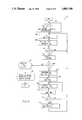
- FIG. 5 is a flow chart of the steps involved in the overall search procedure according to the system of this invention.
- FIG. 6 is a diagram of a preferred search pattern for use with the Level 1 seek according to this invention.
- FIG. 7 is a flow chart of the sort procedure used as part of the Level 1 seek at each incremental position of the satellite antenna along the search pattern of FIG. 6;
- FIG. 8 is a flow chart of the scan procedure used as part of the Level 2 seek according to the system of this invention.
- FIG. 9 is a flow chart of the main stage of the Level 1 seek according to the present invention.
- FIG. 10 is a diagram of a preferred search pattern for use with the Level 2 seek according to this invention.
- FIG. 11 is a flow chart of the Level 2 seek procedure describing how scanning for satellite signals is conducted along the predefined search pattern of FIG. 10;
- FIG. 12 is a flow chart of the Level 3 seek according to the present invention.
- FIG. 13 is a diagram showing a preferred way of repositioning the Level 2 search pattern as part of the Level 3 seek.
- FIG. 14 is a schematic diagram of a preferred noise detector for use in the system of this invention.
- FIG. 1 a functional block diagram of a TVRO earth station for the reception of satellite signals.
- the system includes an antenna 11, which is typically a paraboloidal dish equipped with a low noise block (LNB) converter and related accessories and positioning mechanisms, for capturing signals transmitted from orbiting satellites; and a receiver system including a tuner 12, a demodulator 13, a video processing and amplification section 14, and an audio tuner 15.
- LNB low noise block
- the antenna 11 receives signals transmitted from the satellite in the 4-GHz frequency band (3.7 to 4.2 GHz); and this entire block of frequencies is converted to a 1st IF frequency range of 950 to 1450 MHz by the block converter located at the antenna site.
- the 1st IF signals are then sent via coaxial cable to the tuner 12 which selects a particular channel for viewing and converts the signals in that particular channel to a 2nd IF frequency range.
- the 2nd IF frequency range is preferably high enough to permit the 2nd IF VCO frequencies to be above the 1st IF block of frequencies, to prevent the VCO from interfering with the desired signals.
- a particularly preferred 2nd IF center frequency in the system of the present invention is 612 MHz.
- the 2nd IF signal is passed through an amplifier and a filter and on to a conventional video detector which demodulates the frequency-modulated signal to the baseband of the original video signal (e.g., 0 to 10 MHz), producing a composite video signal output.
- the filter preferably has a pass band that is only about 22 MHz wide; a pass band of this width passes the essential video and audio information while rejecting unwanted noise received by the antenna on the edges of the selected channel.
- the output of the demodulator comprises the baseband signals which range from DC to about 8.5 MHz; this includes video information from about 15 KHz to 4.2 MHz, and subcarriers from about 4.5 to 8.5 MHz.
- FIG. 2 shows a simplified block diagram of a suitable tuner 12 for use in the TVRO system of FIG. 1.
- This tuner 12 includes a passband filter 19 having a passband that is 500 MHz wide (to pass signals in the 1st IF range of 950 to 1450 MHz). From the filter 19, the 1st IF signals are passed through a preamplifier 20 to a superheterodyne circuit including a voltage-controlled oscillator (VCO) 21 receiving a controlling input voltage on line 22, and a mixer 23 for combining the output of the VCO 21 with the 1st IF output of the amplifier 20. This converts the 1st IF signals to a desired 2nd IF frequency range. The resulting 2nd IF signals are passed through a pair of amplifiers 24 and 25 and then on to the demodulator 13.
- VCO voltage-controlled oscillator
- each channel typically contains at least a video carrier signal, a color subcarrier signal, and an audio signal at different prescribed frequencies.
- These carrier and subcarrier signals for all the channels are transmitted simultaneously from the satellite to the earth station antenna 11 and then over a cable to the tuner 12.
- Table I is a list of the center frequencies for 24 transponders on a single satellite. Table I also lists the corresponding center frequencies in the output from the block converter (identified in Table I as the 1st IF center frequencies) and the output frequencies required from the VCO 21 in order to tune the receiver to each individual transponder. It will be noted that the difference between the 1st IF center frequency and the corresponding VCO output frequency for each transponder is 612 MHz, which means that the center frequency of the 2nd IF output from the mixer 23 is 612 MHz for every transponder. That is, the VCO output frequencies listed in Table I will cause the 612-MHz output frequency of the mixer 23 to be centered on the corresponding 1st IF center frequency.
- a VCO output frequency of 2042 MHz will cause the 612-MHz output frequency of the mixer to be centered on the 1430-MHz 1st IF center frequency of transponder No. 1.
- a preferred system for controlling the input voltage to the VCO 21 to produce the desired output frequencies listed above is described in Ma et al. copending U.S. patent application Ser. No. 792,784, filed 10-30-85, for "TVRO Earth Station Receiver for Reducing Interference and Improving Picture Quality.”
- FIG. 3 is a block diagram of a demodulator 13 for receiving the 2nd IF output of the tuner 12 in the TVRO system of FIG. 1.
- This demodulator circuit includes a pair of conventional IF amplifiers 30 and 31 for receiving the 2nd IF signal from the final amplifier 25 in the tuner 12. Both of these amplifiers 30 and 31 receive an automatic gain control (AGC) signal from an input terminal 32. From the amplifier 31, the 2nd IF signal is passed through a filter 33 and on to a conventional video detector 34 which demodulates the frequency-modulated signal to the baseband of the original video signal (e.g., 0 to 10 MHz), producing a composite video output signal.
- the 2nd IF filter 33 preferably has a pass band that is only about 22 MHz wide; a pass band of this width passes the essential video and audio information while rejecting unwanted noise received by the antenna on the edges of the selected channel.
- the AGC feedback loop includes an IF amplifier 36 which amplifies the output of the filter 33 and supplies it to an AGC detector 37.
- the output of this detector 37 is passed through an AGC amplifier 38, which produces a signal strength meter drive signal at a terminal 39.
- This signal strength meter is usually located on the front panel of the TVRO receiver.
- the illustrative demodulator also includes an IF amplifier 40 which receives the same input supplied to the video detector 34, amplifies it, and passes it through a narrow passband filter 41.
- the output of the filter 41 is passed through a detector in the form of a diode 42.
- the signal passed by the diode 42 is smoothed by an amplifier 43 to produce a DC output voltage that can be used to detect the presence of a signal near the center frequency of the particular satellite channel to which the receiver is tuned.
- the output of the demodulator illustrated in FIG. 3 comprises the baseband signals which range from DC to about 8.5 MHz; this includes video information from about 15 KHz to 4.2 MHz, and subcarriers from about 4.5 to 8.5 MHz.
- the video information in these baseband signals is passed through the video processing and amplification section 14 before being displayed on a video monitor or television set, and the audio signals are passed through the audio tuner 15 and then on to one or more speakers which convert the signals to audible sound.
- FIG. 4 is a representation of a typical TVRO earth station 200 including the antenna positioning system, with which the method of the invention may be used to advantage.
- the earth station 200 basically consists of a paraboloidal reception antenna 201 for capturing the satellite television signals, broadcast in the form of a modulated carrier, and focusing them onto a feed horn 202; a low-loss coaxial cable 203 for transferring the received signals from the antenna to a TVRO receiver 204 which processes the modulated signals into a displayable format and performs various other control functions; and a conventional audio/video monitor 205 for reproducing the originally broadcast transmission.
- FIG. 4 also shows a common way of mounting the reception antenna 201 which allows easy movement along both the azimuthal and the elevational directions.
- the antenna 201 is mounted through a swivel mechanism 206 to a support rod 207.
- the extent of swivel motion or azimuthal placement of the antenna is controlled by an electric motor 208 which is connected by a suitable linkage to the swivel mechanism.
- the support rod 207 is mounted on its end remote from the ground, through a thrust bearing or hinge joint 209, to a vertical member 210 usually of fixed height.
- the support axle 207 is mounted through another thrust bearing or hinge joint 211 to a second vertical member 212.
- This member 212 is of controllable height, with an electric motor 213 mounted so as to be capable of adjusting the height of the member 212 and hence the degree of slant or elevation of the antenna 201.
- the above type of mounting generally referred to as a "polar mount" has the advantage that if the support rod is aligned along a true North-by-South line and the elevation adjusted for a heading which is truly southerly, no further adjustments in elevation are required in order to track the complete belt of geo-stationary orbit satellites.
- the provision of the two motors for easily controlling variations in azimuth as well as elevation makes the positioning system versatile and especially applicable to the satellite seeking method according to the system of this invention.
- the extent of the revolutions of the two motors 208 and 213 is measured by special motor pulse extraction circuits within a motor control console 214, to which the motors are connected via supply and sense lines 215 and 216, respectively.
- the pulse extraction circuits use the commutation pulses of the motors as a reference to provide an accurate measurement of the number of revolutions undergone by the motors in a given direction and hence the relative change in the position of the satellite antenna.
- a detailed description of such a circuit is presented in co-pending Ma et al. U.S. patent application Ser. No. 771,667, filed Sept. 3, 1985, for "Motor Pulse Extraction System".
- the information relating to the revolutions of the motors 208 and 213 provides an accurate record of the azimuthal and elevational changes, respectively, which the antenna 201 undergoes.
- This data is fed to a microprocessor in the TVRO receiver 204 and is processed to be used as a part of the satellite seek procedure to be described below.
- the first step 301 is where system initialization takes place and includes the referencing of all system variables involved in the satellite seeking system. Of importance here are the parameters relating the motor controls to the current position of the satellite dish. Also falling within the scope of the system initialization step 301 is the initial setting up of the satellite dish so that it is oriented in the general direction of the geo-stationary satellite orbit belt. This can be accomplished by the use of currently available computer charts that provide the location of every geo-stationary satellite that is within line of sight of given geographic coordinates.
- the satellite earth station antenna can be positioned so that it is approximately oriented toward a known satellite location.
- step 302 is accessed, which in combination with steps 303 and 304 constitutes the Level 3 seek which is explained in detail below with reference to FIGS. 12 and 13.
- Step 302 uses the Level 2 seek procedure (described below in connection with FIG. 11) to search within a predefined area for video signals corresponding to any of the satellite channels.
- a check is made to determine whether any video signals have been detected by the Level 2 seek procedure. If the answer at step 303 is negative, step 304 is reached where the search area for the Level 2 seek is redefined to an adjacent non-overlapping location before reverting to step 302 where a Level 2 seek is reiterated.
- step 305 is accessed, which involves a high resolution Level 1 seek in order to determine the precise position of the antenna dish for optimum reception of signals from the satellite in question.
- L1 the three levels of seek represented in FIG. 5, referred to hereinafter as "L1”, “L2” and “L3”, are described in detail below using their respective flow charts and search patterns.
- FIG. 6 shows the search pattern for the L1 seek procedure, which is the procedure providing the highest degree of resolution.
- the initial part of the L1 seek consists of keeping the antenna at its current position and measuring the noise figure of the received signals. It can be safely assumed that the antenna, during an L1 seek, is oriented in the direction of a receivable satellite because the L1 seek is called in for fine tuning the antenna position only after an L2 seek has located signals from a receivable satellite. Subsequently, all the available channels are scanned, without changing the antenna position, and the system determines which channel, and which polarization angle within that channel, provide optimum reception.
- the L1 seek conducts a search within a predefined area for the antenna position that provides the best reception of this channel. That position then represents the best orientation of the satellite antenna for the reception of all channels from the satellite in consideration.
- the search area is defined by a square ABDC having sides 2° long in both azimuth and elevation, with the initial antenna position in the center of the square.
- the search is started by moving the antenna to point A at the upper left corner of the square, and then along the path shown by the arrows in incremental steps of half a degree in either the azimuthal or the elevational direction. At each new incremental position, a measurement is made for the noise figure related to the channel being scanned.
- a comparison is made at each step to determine the lowest of the measured noise figures.
- the higher noise figure is discarded and the lower noise figure and the satellite position corresponding to it are stored.
- the search reaches the end of the search pattern, i.e., at point D, the current stored value of the noise figure and corresponding antenna position represent the lowest noise figure and the best position of the satellite antenna for the reception of the selected channel and hence the satellite under question.
- FIG. 7 is a flowchart of the "sort" procedure 450 used by the Level 1 seek at each incremental position of the satellite dish along the search pattern of FIG. 6.
- This procedure 450 begins at step 451 which reads the current antenna position as represented by the current azimuth value AZ c and the elevation value EL c .
- the current value N c of the noise figure of the incoming signal is read and stored.
- step 453 a comparison is made between the current noise figure value N c and the previously recorded value N o , and step 454 then determines whether N o is greater than N c . If the answer at step 454 is affirmative, i.e., the previous noise figure is greater than that of the measurement, the present noise figure value N c is substituted for N o at step 455. At the next step 456, the present azimuthal and elevational position values AZ c , EL c are also substituted for the previously stored azimuthal and elevational positions AZ o and EL o .
- step 454 If the answer at step 454 is negative, i.e., the comparison of step 453 shows that the previously stored noise figure value N o is less than the value N c just measured, steps 455 and 456 are bypassed so that there is no change in the stored values N o , AZ o and EL o
- FIG. 8 shows a flow chart 470 for the initial stage of the Level 1 seek.
- this "scan 2" procedure involves the selection of the strongest receivable channel and the best mode of polarization for this channel, with the antenna aimed in the direction in which it was aimed when the Level 1 seek was called for.
- the initial steps 471 and 472 initialize the loop variables SAV c , C c , Co, No and SACC c which respectively represent the current average signal strength, the current channel, the best channel, the noise figure of the best channel, and the current accumulated signal strength of all channels.
- the current channel value C c is read, and at step 474 the current polarization value P c is set to 1.
- the value P c is then used at step 475 to set the polarizer to a predetermined polarization angle.
- the current noise figure value N c and signal strength value S c are read at step 476 (an exemplary system for producing the noise figure values will be described below).
- Step 477 then updates the value SACC c by adding the current signal strength value S c to the previous value SACC p , so that the stored value SACC c always represents the accumulated signal strength of all the channels measured up to any given time.
- step 408 determines whether S c is less than SAV c . If the answer is affirmative, the system advances directly to step 481 where the current polarization value P c is incremented by one. A negative answer at step 478 advances the system to step 479 which determines whether the current noise figure N c is greater than the lowest previously measured noise figure value N o . If the answer is affirmative, the system again proceeds directly to step 481. A negative answer at step 479 advances the system to step 480 where the current values N c , S c and C c are all substituted for the previously stored values N o , S o and C o , and then advances to step 481.
- step 482 determines whether or not the polarization value is greater than four. This particular system is designed to test only four polarization angles in each channel, but of course this number could be varied to increase or decrease the sensitivity of the system to different polarization angles.
- An affirmative answer at step 482 indicates that the desired number of polarization angles have been tested in the current channel, and thus the channel value C p is decremented by one at step 483.
- Step 484 determines when the current channel value C c reaches 0, which is an indication that all channels have been selected. It will be recalled that the value C c was initialized at 24, which means that 24 channels must be tested before an affirmative answer is produced at step 484. Of course, with satellites having a greater or lesser number of transponders, the initialized value of C c can be changed accordingly.
- a negative answer at step 482 returns the system to step 475 so that steps 476 through 482 are repeated for the same channel but with a different polarization angle.
- a negative response at step 484 returns the system to step 473, thereby causing steps 474 through 484 to be repeated for a new channel, and for the desired number of different polarization angles within that channel.
- the average signal strength of all the channels is computed at step 485 as a value SAV c , which is the value SACC c (representing the accumulated single strength of all twenty-four channels) divided by twenty-four.
- Step 486 determines whether the stored value S o , representing the signal strength of the best of all the channels, is less than the average signal strength value SAV c . If an affirmative answer is obtained at step 486, the system returns to step 471 and repeats the entire procedure.
- a negative response at step 486 advances the system to step 487 where the current values C c and P c are set equal to the stored values C o and P o representing the best channel and the best polarization angle for that channel.
- FIG. 9 is a flow chart 400 of the main stage of the Level 1 seek. Prior to the beginning of this stage, the procedure of FIG. 7 has been used to identify the strongest channel receivable from the particular satellite at which the antenna is pointed.
- the satellite antenna is moved along the search pattern defined by FIG. 6 in order to accurately locate the position which provides the best reception of the particular channel identified by the procedure of FIG. 7. This position will then provide the optimum orientation of the antenna for receiving all channels from this particular satellite.
- the first step 401 moves the antenna to the upper left corner of the square to be searched and initialzes a pair of incremental counters ⁇ AZ and ⁇ EL which track the stepwise changes in the position of the satellite antenna in azimuth and elevation, respectively.
- a loop counter N is also initialized.
- the "sort 1" procedure is called into the program. This is the procedure of FIG. 7 and includes the comparison of noise figures of the received signal at the current antenna position and the previous antenna position, and retention of the lower noise figure and corresponding antenna position for further comparison.
- a half degree increment is added to the azimuthal increment counter. This represents a physical movement in the position of the satellite antenna of 0.5 degrees along the azimuth. More specifically, the antenna is now aimed toward a point E which is half a degree to the right of the starting point A in FIG. 6, with no change in elevation.
- a check is made to determine whether the azimuthal limit of the Level 1 search pattern (see FIG. 6) has been reached. This limit corresponds to a value of the azimuth incremental operator ⁇ AZ equal to 2°.
- step 404 If the answer at step 404 is negative, i.e., the satellite has yet to reach the azimuthal limit B of the search pattern, the program reverts to step 402 to continue scanning at half-degree intervals until the end point B is reached, at which time the answer at step 404 becomes affirmative.
- step 405 the loop counter N is incremented by one, followed by a check to see if the counter has reached a value of 3, whose significance is explained below.
- the answer at step 406 will be negative, which advances the system to step 407 where the elevation incremental operator ⁇ EL is decremented by half a degree. This corresponds to a physical movement in the position of the satellite antenna of half a degree in elevation. More specifically, the antenna is now oriented toward a point F which is half a degree lower in elevation than the earlier point B.
- step 407 the "sort 1" procedure described above is called again to evaluate the quality of the signal reception at the current antenna position (point F).
- Step 409 decrements the operator ⁇ AZ by half a degree which represents a physical movement in antenna position of half a degree in azimuth. More specifically, the antenna is now aimed toward a point G which is half a degree displaced from the earlier point F along the decreasing direction of azimuth.
- the "sort 1" procedure is again called into operation to evaluate the signal quality at point G.
- step 411 determines whether the azimuthal limit of the search pattern has been reached. This azimuthal limit is the end point H, which is reached when the value of the azimuth incremental operator ⁇ AZ is equal to zero.
- step 411 If the answer at step 411 is negative, indicating that the antenna has not yet reached the azimuthal end point H, the program reverts to step 409 to continue scanning at half degree intervals until the end point H is reached. When step 411 yields an affirmative answer, the program accesses step 412.
- step 412 the elevation incremental operator is decremented again by half a degree, which as described above corresponds to a physical movement in the antenna position of half a degree in elevation so that the antenna is aimed toward a point displaced by half a degree in elevation from point H.
- the program then reverts to step 402 to reiterate the seek procedure.
- this second pass through the main loop the satellite scans along a path traced out by points I ⁇ J ⁇ K ⁇ L ⁇ C.
- the loop counter reaches a value of 2 during this second pass, the answer at step 406 is still negative, and the antenna continues scanning as in the first pass to finally end up at point C at the end of the second pass.
- the third pass of the program begins with the "sort 1" procedure (step 402) at point C and continues at half degree intervals until the azimuth incremental operator ⁇ AS has reached a value of 2.0 (steps 402, 203, 406), i.e., the azimuth limit or end point D of the Level 1 search pattern is reached.
- the incrementing of the loop counter at step 405 results in a value of 3
- step 406 yields an affirmative answer, and step 413 is accessed.
- the "sort" 1 procedure performs comparisons to detect and store the lowest noise figure and the corresponding antenna position.
- the currently stored value of the antenna position which corresponds to the lowest measured noise figure, represents the optimal position of the satellite antenna for receiving the channel selected by the procedure of FIG. 8.
- the antenna position is shifted to this optimal position and an indication is given at step 414 to show that the desired satellite has been accurately located.
- the located satellite can be identified on the basis of received program content and named.
- the coded name is stored along with the optimal antanna position for automatic repositioning of the antenna in the future.
- FIG. 10 shows the search pattern for the Level 2 seek procedure.
- the Level 2 seek has less resolution than the Level 1 seek and uses a larger search pattern, as defined in FIG. 10 by the rectangular area XYZW with sides of 8 degrees and 6 degrees along the azimuth and the elevation, respectively.
- the search in this case is started at the midpoint M of the side XW of the search pattern, and continued along the path shown by the arrows in incremental steps of one degree in the elevational position and two degrees in the azimuthal position of the antenna dish.
- Level 2 seek is to scan the search pattern for any discernible video indicating the presence of a satellite. Further optimization of the antenna position is then carried out by the Level 1 seek procedure described above.
- the presence of any video signal on any particular channel and at any particular polarization angle can be ascertained in many ways.
- the simplest way is to let a human operator interface with the receiver system during the Level 2 seek and manually push a given control button whenever he sees a semblance of an image on the receiver monitor.
- An automatic but more complex way is to use a built-in artificial intelligence type of pattern recognition system which recognizes the presence of a video image on the receiver monitor screen. In either case, whenever the presence of a video image is sensed, the Level 2 seek can be interrupted to perform the high-resolution Level 1 seek.
- the Level 2 seek can be continued in an adjacent non-overlapping search pattern. This is facilitated by the choice of a symmetrical path for the Level 2 search pattern. For example, in FIG. 10, the search pattern starts at the mid-point M of the side XW and ends at the midpoint V of the side YZ. The next Level 2 seek can hence be conducted directly from point V without any overlapping of search patterns, and without leaving a gap between successive search patterns.
- the Level 2 seek Since the purpose of the Level 2 seek is just to detect the presence of a satellite within a predefined area, without actually locating it accurately, the comparison of noise figures is performed at wider intervals than in the Level 1 seek.
- the increments in the elevational direction are one degree and increments in the azimuthal direction are two degrees each.
- the choice of the two- degree azimuthal increments is dictated by the FCC regulation stipulating a minimum spacing of two earth degrees between orbiting satellites for communications systems. If the antenna increments its azimuthal position more than two degrees at a time, there is a risk of missing a satellite altogether.
- the Level 2 seek provides an extremely rapid means of scanning through all channels at all desired polarization angles to detect the presence of a satellite.
- FIG. 11 is a flowchart 500 of the steps followed by the Level 2 seek procedure in scanning for satellite signals along the predefined search pattern of FIG. 10.
- the first step 501 of the procedure initializes system variables such as the azimuth incremental counter ⁇ AZ and the elevation incremental counter ⁇ EL, which control the stepwise changes in the position of the satellite antenna in azimuth and elevation, respectively. Loop counters N and M are also set to zero at this step.
- the search procedure starts at point M of the search pattern (FIG. 10), and at step 502 the "scan 2" procedure of FIG. 8 is called into the program to determine the channel and polarization angle that produce the lowest noise level.
- the elevation incremental counter ⁇ EL is decremented by one degree. This represents a physical movement in the satellite position of one degree in elevation. More specifically, the antenna is now aimed toward a point N which is displaced from point M by one degree in elevation, without any change in azimuth.
- step 504 the counter N is incremented, and then step 505 determines whether the elevational limit of the Level 2 search pattern (FIG. 10) has been reached. This limit corresponds to a value of the loop counter N equal to 4 since the elevation side of the search pattern is 6° in length and the 1° incremental search is started at the midpoint of the side. If the answer at step 505 is negative, the program returns to step 502 and the scanning is continued at incremental steps of one degree until the point W is reached. At point W the answer at step 505 becomes affirmative, which advances the system to step 506 where the azimuth incremental operator ⁇ AZ is incremented by 2°. This represents a physical movement in the position of the antenna of 2° along the azimuth.
- the antenna is now aimed toward point O which is displaced by 2° in azimuth from the previous point W, without any change in elevation.
- the loop counter N is initialized to zero in order to conveniently use it for further searching, as described below.
- step 507 the "sort 2" procedure is called again.
- step 508 the elevation incremental operator ⁇ EL is incremented by one degree, which produces a change of 1° in the elevational position of the antenna.
- the counter N is then incremented at step 509, and step 510 determines whether the upper elevational limit of the Level 2 search pattern has been reached. This limit corresponds to a loop counter value of 6, since the elevation side of the search pattern is 6° in length. If the answer at step 510 is negative, the program returns to step 507 and the scanning procedure is continued in incremental steps of one degree until the point P is reached. At this point, step 510 yields an affirmative response, which advances the system to step 511 where the azimuth incremental operator is incremented again by 2°. This effectively repositions the antenna so that it is aimed toward point Q which is displaced by 2° in azimuth from the previous point P.
- step 512 the "scan 2" procedure is again recalled into the program, and the loop counter N is reset to zero.
- the elevation incremental operator ⁇ EL is then decremented by one degree at step 513, resulting in a change of one degree in the elevational position of the antenna.
- the search pattern of FIG. 10 can be symmetrically split into two segments.
- the first one as tracked by the program so far, comprises the path traced by points M, W, O, P, Q, and R.
- the second segment is identical to the first, except for a displacement in azimuth, and comprises the path traced by the points R, S, T, U, Y and V.
- the program described so far can be repeated using the point R as the starting point.
- step 516 the loop counter N is initialized to zero and the loop counter M is incremented to mark the end of scanning of the first segment.
- the choice of search pattern is important for the proper functioning of the Level 2 seek procedure. It must be chosen in such a way that the succeeding Level 2 seek may be implemented immediately at the end of the previous one without allowing any overlapping or skipping of the search area. For example, at the end of a Level 2 seek, according to the search pattern of FIG. 10, the antenna is oriented toward point V, and the succeeding Level 2 seek can be started at point V without any overlapping or skipping of the search area.
- FIG. 12 is a flow chart of the Level 3 seek procedure according to the system of this invention.
- the Level 3 seek procedure involves the positioning of the satellite antenna in order to perform Level 2 seeks, according to the Level 2 search pattern, at adjacent non-overlapping positions until a receivable satellite signal is detected.
- the current physical position of the antenna is recorded in terms of azimuth and elevation readings AZ c and EL c .
- a Level 2 seek is performed at the current antenna position.
- Step 603 determines whether a video flag is set, indicating the detection of a video transmission by the Level 2 seek. If the answer is affirmative, the program reaches step 604 where either come to a halt until a Level 1 seek is specifically called for or it may proceed automatically with a Level 1 seek centered at the antenna position where the video transmission was detected.
- step 603 If the answer at step 603 is negative, i.e., the Level 2 seek has produced no discernible video signals at the current antenna position, the Level 2 seek is repositioned at an adjacent but non-overlapping location at step 603, and the program returns to step 601 to continue with the satellite search procedure.
- FIG. 13 shows one possible way of implementing the Level 3 search.
- the Level 2 seek search area or patch is moved from its current patch to an adjacent and non-overlapping patch 1. This repositioning is continued along a spiraling path as defined in part by patches 2 through 12.
- the satellite antenna is made to track the sky along a predefined, gradually expanding and non-overlapping spiral path until a Level 2 seek detects the presence of video signals.
- a Level 1 seek may be called to zero in on the satellite broadcasting the video signals, or until the physical constraints on the motion of the antenna are reached.
- all positioning and referencing of the antenna as part of the overall satellite seek procedure are based on the extent of revolution of the two positioning motors as referenced by the pulse count at the motor control block of FIG. 4.
- the pulse counters for the two motor pulse extraction systems are initialized so that all further movement of the antenna may be referenced conveniently. All subsequent changes in the azimuthal and elevational readings are tracked and recorded by the microprocessor within the TVRO receiver system.
- the antenna may be conveniently and automatically repositioned to be oriented directly toward the same satellite whenever needed.
- the basic search procedure according to the system described above can be undergone again in order to redefine the optimum position of the antenna for the satellite in question.
- the earth station antenna can be used to successively seek all satellites broadcasting commerically from the geo-synchronous orbit belt, and to record the optimum antenna positions for the respective satellites in terms of the displacement of the positioning motors.
- a database of satellite antenna positions is set up, locating a satellite or shifting from one satellite to the other automatically is a simple matter of recalling the appropriate antenna position from the database in memory and then controlling the positioning system to properly orient the antenna.
- fine tuning of the antenna position can be performed as mentioned above, and the new antenna position can be used to update the earlier position recorded within the database.
- FIG. 14 shows the details of a preferred noise detector for furnishing the microprocessor with the noise figure values referred to above.
- the video baseband signal from the demodulator 13 is initially fed through a bandpass filter 60 which preferably has a pass band that is about 500 KHz wide centered at about 23 MHz, which is well above the video information in the baseband signal.
- the 23-MHz center frequency also avoids interference from 27-MHz CB signals, 21-MHz and 24.5-MHz ham radio signals, and harmonics of the 4-MHz output of the crystal oscillator in the tuner 12.
- the output of the bandpass filter 60 is passed through a conventional RF amplifier 61 to a detector in the form of a diode 62.
- This diode 62 rectifies the AC output from the amplifier 61, and the resulting signal is smoothed by passing it through a DC amplifier 63 and a low pass filter 64. It is the smooth DC output of the filter 64 that is applied to the microprocessor via an analog-to-digital converter; the magnitude of this DC signal will vary in direct proportion to the noise level in the video baseband output from the demodulator.
- the polarization angle referred to above is adjusted by a microprocessor output signal which is passed through a digital-to-analog converter to produce a DC voltage for application to a conventional polarizer.
- TVRO systems normally include polarizers which can adjust the relative alignment of the polarization of the incoming signals and the orientation of the antenna.
- One type of polarizer mechanically rotates the small probe that is included in the feed horn of most earth station antennas, by means of a small servomotor which is powered by either the indoor receiver or an antenna positioner.
- a second type of polarizer adjusts the polarization of the incoming signal electronically, by changing the voltage applied to a coil wound around an electromagnetic ferrite core located at the throat of the feedhorn.
- the ferrite-core polarizer essentially acts as a controlling phase shifter and has a feed horn arrangement for accepting the incoming satellite signals and then passing them through the ferrite core.
- a voltage is applied across the coil, an electromagnetic field of corresponding strength is set up around the ferrite core. This field interacts with the electromagnetic fields propagating through the core and rotates the plane of polarization of the received signals to a predetermined angle corresponding to the magnitude of the DC voltage applied to the coil.
Abstract
Description
              TABLE I
______________________________________
         Trans-
Transponder
         ponder    1st IF    VCO     2nd IF
Number   Center    Center    Output  Center
("Channel")
         Freq.     Freq.     Freq.   Freq.
______________________________________
         3720 MHz  1430 MHz  2042 MHz
                                     612 MHz
2        3740      1410      2022    612
3        3760      1390      2002    612
4        3780      1370      1982    612
5        3800      1350      1962    612
6        3820      1330      1942    612
7        3840      1310      1922    612
8        3860      1290      1902    612
9        3880      1270      1882    612
10       3900      1250      1862    612
11       3920      1230      1842    612
12       3940      1210      1822    612
13       3960      1190      1802    612
14       3980      1170      1782    612
15       4000      1150      1762    612
16       4020      1130      1742    612
17       4040      1110      1722    612
18       4060      1090      1702    612
19       4080      1070      1682    612
20       4100      1050      1662    612
21       4120      1030      1642    612
22       4140      1010      1622    612
23       4160       990      1602    612
24       4180       970      1582    612
______________________________________
Claims (23)
Priority Applications (1)
| Application Number | Priority Date | Filing Date | Title |
|---|---|---|---|
| US06/792,786 US4801940A (en) | 1985-10-30 | 1985-10-30 | Satellite seeking system for earth-station antennas for TVRO systems |
Applications Claiming Priority (1)
| Application Number | Priority Date | Filing Date | Title |
|---|---|---|---|
| US06/792,786 US4801940A (en) | 1985-10-30 | 1985-10-30 | Satellite seeking system for earth-station antennas for TVRO systems |
Publications (1)
| Publication Number | Publication Date |
|---|---|
| US4801940A true US4801940A (en) | 1989-01-31 |
Family
ID=25158066
Family Applications (1)
| Application Number | Title | Priority Date | Filing Date |
|---|---|---|---|
| US06/792,786 Expired - Fee Related US4801940A (en) | 1985-10-30 | 1985-10-30 | Satellite seeking system for earth-station antennas for TVRO systems |
Country Status (1)
| Country | Link |
|---|---|
| US (1) | US4801940A (en) |
Cited By (31)
| Publication number | Priority date | Publication date | Assignee | Title |
|---|---|---|---|---|
| US4862179A (en) * | 1985-03-26 | 1989-08-29 | Trio Kabushiki Kaisha | Satellite receiver |
| US5077561A (en) * | 1990-05-08 | 1991-12-31 | Hts | Method and apparatus for tracking satellites in inclined orbits |
| US5296862A (en) * | 1992-11-18 | 1994-03-22 | Winegard Company | Method for automatically positioning a satellite dish antenna to satellites in a geosynchronous belt |
| FR2698173A1 (en) * | 1992-11-19 | 1994-05-20 | Berton Jean | Equipment for controlling orientation of parabolic antenna - uses demodulator connected to head of parabolic antenna to feed indicating meter and tv set |
| US5319673A (en) * | 1992-04-10 | 1994-06-07 | Cd Radio Inc. | Radio frequency broadcasting systems and methods using two low-cost geosynchronous satellites |
| AU651508B2 (en) * | 1991-12-12 | 1994-07-21 | Nec Corporation | Method and arrangement of pointing an antenna beam to a stationary satellite |
| US5376941A (en) * | 1992-10-30 | 1994-12-27 | Uniden Corporation | Antenna direction adjusting method and apparatus for satellite broadcasting receiving system |
| US5422648A (en) * | 1991-12-10 | 1995-06-06 | Nippon Steel Corporation | Receiving antenna apparatus for broadcast by satellite |
| EP0687029A1 (en) * | 1994-06-09 | 1995-12-13 | Thomson Consumer Electronics, Inc. | Apparatus and method for aligning a receiving antenna utilizing an audible tone |
| US5488379A (en) * | 1995-01-05 | 1996-01-30 | Hughes Aircraft Company | Apparatus and method for positioning an antenna in a remote ground terminal |
| US5583514A (en) * | 1994-03-07 | 1996-12-10 | Loral Aerospace Corp. | Rapid satellite acquisition device |
| US5585804A (en) * | 1992-11-18 | 1996-12-17 | Winegard Company | Method for automatically positioning a satellite dish antenna to satellites in a geosynchronous belt |
| US5592471A (en) * | 1995-04-21 | 1997-01-07 | Cd Radio Inc. | Mobile radio receivers using time diversity to avoid service outages in multichannel broadcast transmission systems |
| US5687084A (en) * | 1992-05-26 | 1997-11-11 | Microcosm, Inc. | Satellite orbit maintenance system |
| US5990822A (en) * | 1989-04-14 | 1999-11-23 | Honigsbaum; Richard F. | Process and apparatus for finding stealthcraft |
| US6023616A (en) * | 1998-03-10 | 2000-02-08 | Cd Radio Inc. | Satellite broadcast receiver system |
| US6223019B1 (en) | 1996-03-14 | 2001-04-24 | Sirius Satellite Radio Inc. | Efficient high latitude service area satellite mobile broadcasting systems |
| US6337658B1 (en) * | 1999-11-30 | 2002-01-08 | Nortel Networks Limited | Transmit antenna alignment peak search method and apparatus |
| US20020083458A1 (en) * | 2000-12-21 | 2002-06-27 | Henderson John G. N. | Steerable antenna and receiver interface for terrestrial broadcast |
| US20020128046A1 (en) * | 2001-03-01 | 2002-09-12 | Kddi R&D Laboratories Inc. | Radio LAN master station system |
| KR20020086157A (en) * | 2001-05-11 | 2002-11-18 | 주식회사 한단정보통신 | An automatic satellite & channel searching system in the satellite broadcasting receiver which has a positioner and the automatic satellite & channel searching method thereof |
| US20030035386A1 (en) * | 2001-05-11 | 2003-02-20 | Mark Sullivan | Apparatus and method for efficient live webcasting and network connectivity |
| US6697610B1 (en) * | 2000-06-15 | 2004-02-24 | Zenith Electronics Corporation | Smart antenna for RF receivers |
| WO2005027259A2 (en) * | 2003-09-18 | 2005-03-24 | Thomson Licensing | Low-cost automatic antenna pointing system of satellite transmission/reception terminal |
| US20060003690A1 (en) * | 2004-06-25 | 2006-01-05 | Funai Electric Co., Ltd. | Broadcast receiver |
| US20070005336A1 (en) * | 2005-03-16 | 2007-01-04 | Pathiyal Krishna K | Handheld electronic device with reduced keyboard and associated method of providing improved disambiguation |
| US20090160701A1 (en) * | 2004-12-01 | 2009-06-25 | Seong-Ho Son | Apparatus for identifying target satellite in satellite communication antenna and method thereof |
| US20090209277A1 (en) * | 2008-02-19 | 2009-08-20 | Gilat Satellite Networks, Ltd. | Satellite Redundancy for Critical Applications |
| WO2010077212A1 (en) * | 2008-12-31 | 2010-07-08 | Neta Elektronik Cihazlar San. Ve Tic. A.S. | Mobile satellite tracking antenna and the system thereof |
| CN102723602A (en) * | 2012-06-29 | 2012-10-10 | 深圳市九洲电器有限公司 | Automatic satellite finding method and satellite finding device |
| US20130050021A1 (en) * | 2011-08-25 | 2013-02-28 | Fimax Technology Limited | Wireless cable |
Citations (14)
| Publication number | Priority date | Publication date | Assignee | Title |
|---|---|---|---|---|
| US3089137A (en) * | 1959-07-01 | 1963-05-07 | Bell Telephone Labor Inc | Polarization tracking receiver |
| US3093825A (en) * | 1959-02-26 | 1963-06-11 | Philip J Allen | Polarimeter |
| US3311916A (en) * | 1964-10-20 | 1967-03-28 | Bell Telephone Labor Inc | Nondegenerate multimode tracking system |
| US3383688A (en) * | 1964-11-20 | 1968-05-14 | Comp Generale Electricite | Systems for controlling the automatic tracking in high frequency antennas |
| US3523294A (en) * | 1968-01-24 | 1970-08-04 | Tokyo Shibaura Electric Co | Polarization-plane tracking receiving system |
| US3530471A (en) * | 1967-04-04 | 1970-09-22 | Marconi Co Ltd | Automatic tracking radio equipments |
| US3772701A (en) * | 1971-02-11 | 1973-11-13 | Communications Satellite Corp | Satellite antenna autotrack system permitting error signals to appear at the earth station |
| US3842420A (en) * | 1972-10-13 | 1974-10-15 | Itt | Step tracking system |
| US4030099A (en) * | 1974-12-12 | 1977-06-14 | Westinghouse Electric Corporation | Digital antenna control apparatus for a communications terminal |
| US4090201A (en) * | 1976-09-08 | 1978-05-16 | Harris Corporation | Rate augmented step track system |
| US4336542A (en) * | 1978-11-06 | 1982-06-22 | Cselt, Centro Studi E Laboratori Telecomunicazioni S.P.A. | Method of and system for tracking an object radiating a circularly or linearly polarized electromagnetic signal |
| US4358767A (en) * | 1980-01-08 | 1982-11-09 | Neyrpic | Method of tracking for telecommunications antennae |
| US4418350A (en) * | 1981-03-23 | 1983-11-29 | Hughes Aircraft Company | Two-axis antenna direction control system |
| US4542326A (en) * | 1982-10-08 | 1985-09-17 | Heath Company | Automatic antenna positioning system |
-
1985
- 1985-10-30 US US06/792,786 patent/US4801940A/en not_active Expired - Fee Related
Patent Citations (14)
| Publication number | Priority date | Publication date | Assignee | Title |
|---|---|---|---|---|
| US3093825A (en) * | 1959-02-26 | 1963-06-11 | Philip J Allen | Polarimeter |
| US3089137A (en) * | 1959-07-01 | 1963-05-07 | Bell Telephone Labor Inc | Polarization tracking receiver |
| US3311916A (en) * | 1964-10-20 | 1967-03-28 | Bell Telephone Labor Inc | Nondegenerate multimode tracking system |
| US3383688A (en) * | 1964-11-20 | 1968-05-14 | Comp Generale Electricite | Systems for controlling the automatic tracking in high frequency antennas |
| US3530471A (en) * | 1967-04-04 | 1970-09-22 | Marconi Co Ltd | Automatic tracking radio equipments |
| US3523294A (en) * | 1968-01-24 | 1970-08-04 | Tokyo Shibaura Electric Co | Polarization-plane tracking receiving system |
| US3772701A (en) * | 1971-02-11 | 1973-11-13 | Communications Satellite Corp | Satellite antenna autotrack system permitting error signals to appear at the earth station |
| US3842420A (en) * | 1972-10-13 | 1974-10-15 | Itt | Step tracking system |
| US4030099A (en) * | 1974-12-12 | 1977-06-14 | Westinghouse Electric Corporation | Digital antenna control apparatus for a communications terminal |
| US4090201A (en) * | 1976-09-08 | 1978-05-16 | Harris Corporation | Rate augmented step track system |
| US4336542A (en) * | 1978-11-06 | 1982-06-22 | Cselt, Centro Studi E Laboratori Telecomunicazioni S.P.A. | Method of and system for tracking an object radiating a circularly or linearly polarized electromagnetic signal |
| US4358767A (en) * | 1980-01-08 | 1982-11-09 | Neyrpic | Method of tracking for telecommunications antennae |
| US4418350A (en) * | 1981-03-23 | 1983-11-29 | Hughes Aircraft Company | Two-axis antenna direction control system |
| US4542326A (en) * | 1982-10-08 | 1985-09-17 | Heath Company | Automatic antenna positioning system |
Cited By (53)
| Publication number | Priority date | Publication date | Assignee | Title |
|---|---|---|---|---|
| US4862179A (en) * | 1985-03-26 | 1989-08-29 | Trio Kabushiki Kaisha | Satellite receiver |
| US5990822A (en) * | 1989-04-14 | 1999-11-23 | Honigsbaum; Richard F. | Process and apparatus for finding stealthcraft |
| US5077561A (en) * | 1990-05-08 | 1991-12-31 | Hts | Method and apparatus for tracking satellites in inclined orbits |
| US5422648A (en) * | 1991-12-10 | 1995-06-06 | Nippon Steel Corporation | Receiving antenna apparatus for broadcast by satellite |
| US5463401A (en) * | 1991-12-12 | 1995-10-31 | Nec Corporation | Method and arrangement of pointing an antenna beam to a stationary satellite |
| AU651508B2 (en) * | 1991-12-12 | 1994-07-21 | Nec Corporation | Method and arrangement of pointing an antenna beam to a stationary satellite |
| US5319673A (en) * | 1992-04-10 | 1994-06-07 | Cd Radio Inc. | Radio frequency broadcasting systems and methods using two low-cost geosynchronous satellites |
| US5687084A (en) * | 1992-05-26 | 1997-11-11 | Microcosm, Inc. | Satellite orbit maintenance system |
| US5376941A (en) * | 1992-10-30 | 1994-12-27 | Uniden Corporation | Antenna direction adjusting method and apparatus for satellite broadcasting receiving system |
| US5471219A (en) * | 1992-11-18 | 1995-11-28 | Winegard Company | Method for automatically positioning a satellite dish antenna to satellites in a geosynchronous belt |
| US5585804A (en) * | 1992-11-18 | 1996-12-17 | Winegard Company | Method for automatically positioning a satellite dish antenna to satellites in a geosynchronous belt |
| US5296862A (en) * | 1992-11-18 | 1994-03-22 | Winegard Company | Method for automatically positioning a satellite dish antenna to satellites in a geosynchronous belt |
| FR2698173A1 (en) * | 1992-11-19 | 1994-05-20 | Berton Jean | Equipment for controlling orientation of parabolic antenna - uses demodulator connected to head of parabolic antenna to feed indicating meter and tv set |
| US5583514A (en) * | 1994-03-07 | 1996-12-10 | Loral Aerospace Corp. | Rapid satellite acquisition device |
| CN1084936C (en) * | 1994-06-09 | 2002-05-15 | 汤姆森消费电子有限公司 | Apparatus and method for aligning a receiving antenna utilizing an audible tone |
| EP0687029A1 (en) * | 1994-06-09 | 1995-12-13 | Thomson Consumer Electronics, Inc. | Apparatus and method for aligning a receiving antenna utilizing an audible tone |
| US5561433A (en) * | 1994-06-09 | 1996-10-01 | Thomson Consumer Electronics, Inc. | Apparatus and method for aligning a receiving antenna utilizing an audible tone |
| US5488379A (en) * | 1995-01-05 | 1996-01-30 | Hughes Aircraft Company | Apparatus and method for positioning an antenna in a remote ground terminal |
| WO1996021253A1 (en) * | 1995-01-05 | 1996-07-11 | Hughes Aircraft Company | Apparatus and method for positioning an antenna in a remote ground terminal |
| US5592471A (en) * | 1995-04-21 | 1997-01-07 | Cd Radio Inc. | Mobile radio receivers using time diversity to avoid service outages in multichannel broadcast transmission systems |
| US6223019B1 (en) | 1996-03-14 | 2001-04-24 | Sirius Satellite Radio Inc. | Efficient high latitude service area satellite mobile broadcasting systems |
| US6023616A (en) * | 1998-03-10 | 2000-02-08 | Cd Radio Inc. | Satellite broadcast receiver system |
| US6564053B1 (en) | 1998-05-20 | 2003-05-13 | Sirius Satellite Radio Inc. | Efficient high latitude service area satellite mobile broadcasting systems |
| US6337658B1 (en) * | 1999-11-30 | 2002-01-08 | Nortel Networks Limited | Transmit antenna alignment peak search method and apparatus |
| USRE41540E1 (en) | 2000-06-15 | 2010-08-17 | Zenith Electronics LCC | Smart antenna for RF receivers |
| US6697610B1 (en) * | 2000-06-15 | 2004-02-24 | Zenith Electronics Corporation | Smart antenna for RF receivers |
| US20020083458A1 (en) * | 2000-12-21 | 2002-06-27 | Henderson John G. N. | Steerable antenna and receiver interface for terrestrial broadcast |
| US8125386B2 (en) | 2000-12-21 | 2012-02-28 | Hitachi America, Ltd. | Steerable antenna and receiver interface for terrestrial broadcast |
| US20060145918A1 (en) * | 2000-12-21 | 2006-07-06 | Henderson John G | Steerable antenna and receiver interface for terrestrial broadcast |
| US7425920B2 (en) | 2000-12-21 | 2008-09-16 | Hitachi America, Ltd. | Steerable antenna and receiver interface for terrestrial broadcast |
| US7006040B2 (en) * | 2000-12-21 | 2006-02-28 | Hitachi America, Ltd. | Steerable antenna and receiver interface for terrestrial broadcast |
| US20020128046A1 (en) * | 2001-03-01 | 2002-09-12 | Kddi R&D Laboratories Inc. | Radio LAN master station system |
| US7123941B2 (en) * | 2001-03-01 | 2006-10-17 | Kddi R&D Laboratories Inc. | Radio LAN master station system |
| KR20020086157A (en) * | 2001-05-11 | 2002-11-18 | 주식회사 한단정보통신 | An automatic satellite & channel searching system in the satellite broadcasting receiver which has a positioner and the automatic satellite & channel searching method thereof |
| US20030035386A1 (en) * | 2001-05-11 | 2003-02-20 | Mark Sullivan | Apparatus and method for efficient live webcasting and network connectivity |
| US7215648B2 (en) * | 2001-05-11 | 2007-05-08 | Varitek Industries, Inc. | Apparatus and method for efficient live webcasting and network connectivity |
| WO2005027259A3 (en) * | 2003-09-18 | 2005-05-12 | Thomson Licensing Sa | Low-cost automatic antenna pointing system of satellite transmission/reception terminal |
| WO2005027259A2 (en) * | 2003-09-18 | 2005-03-24 | Thomson Licensing | Low-cost automatic antenna pointing system of satellite transmission/reception terminal |
| US7603077B2 (en) * | 2004-06-25 | 2009-10-13 | Funai Electric Co., Ltd. | Broadcast receiver with automatic channel scanning |
| US20060003690A1 (en) * | 2004-06-25 | 2006-01-05 | Funai Electric Co., Ltd. | Broadcast receiver |
| US7696926B2 (en) * | 2004-12-01 | 2010-04-13 | Electronics And Telecommunications Research Institute | Apparatus for identifying target satellite in satellite communication antenna and method thereof |
| US20090160701A1 (en) * | 2004-12-01 | 2009-06-25 | Seong-Ho Son | Apparatus for identifying target satellite in satellite communication antenna and method thereof |
| US20070005336A1 (en) * | 2005-03-16 | 2007-01-04 | Pathiyal Krishna K | Handheld electronic device with reduced keyboard and associated method of providing improved disambiguation |
| EP2093900A2 (en) * | 2008-02-19 | 2009-08-26 | Gilat Satellite Networks, Ltd. | Satellite redundancy for critical applications |
| US20090209277A1 (en) * | 2008-02-19 | 2009-08-20 | Gilat Satellite Networks, Ltd. | Satellite Redundancy for Critical Applications |
| EP2093900A3 (en) * | 2008-02-19 | 2013-02-06 | Gilat Satellite Networks, Ltd. | Satellite redundancy for critical applications |
| WO2010077212A1 (en) * | 2008-12-31 | 2010-07-08 | Neta Elektronik Cihazlar San. Ve Tic. A.S. | Mobile satellite tracking antenna and the system thereof |
| US20130050021A1 (en) * | 2011-08-25 | 2013-02-28 | Fimax Technology Limited | Wireless cable |
| CN103037383A (en) * | 2011-08-25 | 2013-04-10 | 快美思科技有限公司 | Wireless cable |
| US8704711B2 (en) * | 2011-08-25 | 2014-04-22 | Fimax Technology Limited | Wireless cable |
| CN103037383B (en) * | 2011-08-25 | 2018-05-22 | 快美思科技有限公司 | Wireless cable |
| CN102723602A (en) * | 2012-06-29 | 2012-10-10 | 深圳市九洲电器有限公司 | Automatic satellite finding method and satellite finding device |
| CN102723602B (en) * | 2012-06-29 | 2014-07-02 | 深圳市九洲电器有限公司 | Automatic satellite finding method and satellite finding device |
Similar Documents
| Publication | Publication Date | Title |
|---|---|---|
| US4801940A (en) | Satellite seeking system for earth-station antennas for TVRO systems | |
| US5296862A (en) | Method for automatically positioning a satellite dish antenna to satellites in a geosynchronous belt | |
| US5585804A (en) | Method for automatically positioning a satellite dish antenna to satellites in a geosynchronous belt | |
| US4796032A (en) | Satellite broadcasting receiving system | |
| EP0132382B1 (en) | Direct satellite broadcast receiving system | |
| CA2149695C (en) | Apparatus and method for aligning a receiving antenna utilizing an audible tone | |
| US6216266B1 (en) | Remote control signal level meter | |
| US4785302A (en) | Automatic polarization control system for TVRO receivers | |
| US5038405A (en) | Tunable antenna apparatus and method for use with superheterodyne receivers | |
| EP0373604B1 (en) | Direction tracking antenna system | |
| US8466965B2 (en) | Wall plate digital television antenna signal meter and method | |
| US4477812A (en) | Signal acquisition and tracking system | |
| US20020057225A1 (en) | Automatic pointing antennae system | |
| US20050113032A1 (en) | Reception system including a pointing aid device | |
| EP0389494A1 (en) | Automatic polarization control system for tvro receivers | |
| US8175560B2 (en) | Method and system for tuning an antenna | |
| KR100519026B1 (en) | Auto-direction selector for antenna | |
| JPH0139021Y2 (en) | ||
| JPS59133707A (en) | Controller for direction of antenna | |
| JP2885300B2 (en) | Satellite positioning system | |
| Franklin et al. | A data acquisition and processing system for mass producing topside ionograms | |
| JP2000333214A (en) | Single channel spectrum analyzer | |
| JPH0155637B2 (en) | ||
| Gandy | A helicopter-tracking receiver for television outside broadcast links | |
| JPS5910604B2 (en) | Receiving antenna device |
Legal Events
| Date | Code | Title | Description |
|---|---|---|---|
| AS | Assignment |
Owner name: CAPETRONIC (BSR) LTD., C/O CIC EXPORT LIMITED, ROO Free format text: ASSIGNMENT OF ASSIGNORS INTEREST.;ASSIGNORS:MA, JOHN Y.;MC CRACKEN, DAVID H.;WEISS, STEVEN;AND OTHERS;REEL/FRAME:004498/0266 Effective date: 19851030 |
|
| FEPP | Fee payment procedure |
Free format text: PAYER NUMBER DE-ASSIGNED (ORIGINAL EVENT CODE: RMPN); ENTITY STATUS OF PATENT OWNER: LARGE ENTITY Free format text: PAYOR NUMBER ASSIGNED (ORIGINAL EVENT CODE: ASPN); ENTITY STATUS OF PATENT OWNER: LARGE ENTITY |
|
| AS | Assignment |
Owner name: ASTEC INTERNATIONAL, LTD., 6/FL. KAISER ESTATE PHA Free format text: ASSIGNMENT OF ASSIGNORS INTEREST.;ASSIGNOR:ASTEC INTERNATIONAL (BERMUDA) LTD., FORMERLY CAPETRONIC (BSR) LTD.;REEL/FRAME:005539/0297 Effective date: 19901016 |
|
| FPAY | Fee payment |
Year of fee payment: 4 |
|
| REMI | Maintenance fee reminder mailed | ||
| LAPS | Lapse for failure to pay maintenance fees | ||
| FP | Lapsed due to failure to pay maintenance fee |
Effective date: 19970205 |
|
| STCH | Information on status: patent discontinuation |
Free format text: PATENT EXPIRED DUE TO NONPAYMENT OF MAINTENANCE FEES UNDER 37 CFR 1.362 |