US4796237A - Method for acoustic reverberation removal - Google Patents
Method for acoustic reverberation removal Download PDFInfo
- Publication number
- US4796237A US4796237A US07/008,015 US801587A US4796237A US 4796237 A US4796237 A US 4796237A US 801587 A US801587 A US 801587A US 4796237 A US4796237 A US 4796237A
- Authority
- US
- United States
- Prior art keywords
- acoustic
- casing
- signal
- pulse
- acoustic energy
- Prior art date
- Legal status (The legal status is an assumption and is not a legal conclusion. Google has not performed a legal analysis and makes no representation as to the accuracy of the status listed.)
- Expired - Fee Related
Links
- 238000000034 method Methods 0.000 title claims abstract description 26
- 239000004568 cement Substances 0.000 claims description 24
- 230000005540 biological transmission Effects 0.000 claims description 13
- 230000007547 defect Effects 0.000 claims description 7
- 230000003111 delayed effect Effects 0.000 claims description 3
- 230000002708 enhancing effect Effects 0.000 claims 4
- 239000000725 suspension Substances 0.000 claims 2
- 238000002592 echocardiography Methods 0.000 description 5
- 238000005259 measurement Methods 0.000 description 5
- 230000000694 effects Effects 0.000 description 4
- 238000010304 firing Methods 0.000 description 4
- 230000015572 biosynthetic process Effects 0.000 description 3
- 230000003247 decreasing effect Effects 0.000 description 3
- 238000010586 diagram Methods 0.000 description 3
- 238000004458 analytical method Methods 0.000 description 2
- 230000003321 amplification Effects 0.000 description 1
- 230000003466 anti-cipated effect Effects 0.000 description 1
- 238000006243 chemical reaction Methods 0.000 description 1
- 230000001143 conditioned effect Effects 0.000 description 1
- 230000008602 contraction Effects 0.000 description 1
- 230000001934 delay Effects 0.000 description 1
- 238000001514 detection method Methods 0.000 description 1
- 238000003384 imaging method Methods 0.000 description 1
- 239000000463 material Substances 0.000 description 1
- 238000012986 modification Methods 0.000 description 1
- 230000004048 modification Effects 0.000 description 1
- 238000003199 nucleic acid amplification method Methods 0.000 description 1
- 238000009877 rendering Methods 0.000 description 1
- 230000003252 repetitive effect Effects 0.000 description 1
- 230000001360 synchronised effect Effects 0.000 description 1
Images


Classifications
-
- G—PHYSICS
- G01—MEASURING; TESTING
- G01V—GEOPHYSICS; GRAVITATIONAL MEASUREMENTS; DETECTING MASSES OR OBJECTS; TAGS
- G01V1/00—Seismology; Seismic or acoustic prospecting or detecting
- G01V1/40—Seismology; Seismic or acoustic prospecting or detecting specially adapted for well-logging
- G01V1/44—Seismology; Seismic or acoustic prospecting or detecting specially adapted for well-logging using generators and receivers in the same well
- G01V1/46—Data acquisition
-
- G—PHYSICS
- G01—MEASURING; TESTING
- G01S—RADIO DIRECTION-FINDING; RADIO NAVIGATION; DETERMINING DISTANCE OR VELOCITY BY USE OF RADIO WAVES; LOCATING OR PRESENCE-DETECTING BY USE OF THE REFLECTION OR RERADIATION OF RADIO WAVES; ANALOGOUS ARRANGEMENTS USING OTHER WAVES
- G01S7/00—Details of systems according to groups G01S13/00, G01S15/00, G01S17/00
- G01S7/52—Details of systems according to groups G01S13/00, G01S15/00, G01S17/00 of systems according to group G01S15/00
- G01S7/523—Details of pulse systems
- G01S7/526—Receivers
- G01S7/527—Extracting wanted echo signals
Definitions
- the present invention relates to a method for improving the signal-to-noise ratio of a signal and, more particularly, to such a method for removing acoustic reverberations from the received signal.
- the transducer material When an acoustic transducer has an electrical current passing across it, the transducer material will expand or contract to generate a positive or negative respectively pulse of acoustic energy.
- the acoustic energy passes through the surrounding environment and portions of the acoustic energy will be reflected back to the transducer upon contacting boundaries between disparate mediums.
- the magnitude and time duration of the ringing is such that reflections from other outer boundaries can be totally obscured, that is, the ratio of the signal desired to be investigated to the ringing from the thin layer is considered so poor as rendering an analysis of the signal ineffective. An example of this problem will be described below.
- ultrasonic transducers in contact with the well casing can be used to investigate the quality of the cement bond between the column of cement surrounding a casing set within a wellbore.
- This tool utilizes one or more acoustic energy transducers to transmit acoustic energy pulses that pass through the casing, cement, and the surrounding formation. The acoustic reflections are received within the tool to produce a signal for analysis by an operator at the surface.
- the acoustic problem exists here because a thin, highly acoustically mismatched medium, i.e., the casing, exists between the transducer and the medium to be interrogated, i.e., the cement.
- the casing causes ringing, and this ringing obscures the portions of the received signals of interest, such as reflections from cement defects interface and the cement-formation interface.
- the present invention provides a method and related system for canceling acoustic reverberations caused when acoustic energy from a source, such as a transducer, impinges a layer, such as a casing.
- a positive acoustic pulse is transmitted, and the amplitudes of each of the resulting acoustic reverberations are measured.
- a negative acoustic pulse is transmitted with an ampitude equal to the immediately preceding received acoustic reverberation from the positive pulse.
- the time between the transmission of the positive acoustic pulse to the transmission of the negative acoustic pulse to cancel the effects of the acoustic reverberations is varied so that the negative acoustic pulses counteract or drive the acoustic reverberations to a null.
- FIG. 1A is a cut away elevational view of an ultrasonic device, embodying the present invention, having a transducer placed in contact with a casing for identifying cement defects.
- FIG. 1B is a signal amplitude vs time plot of a received signal from the transducer shown in FIG. 1A.
- FIG. 2 is a diagrammatic representation of a series of positive acoustic reverberations and a corresponding series of negative acoustic pulses used to cancel the positive acoustic reverberations.
- FIGS. 3A and 3B are diagrammatic representations of a series of acoustic pulses being reflected by casing and cement.
- FIG. 4A is a circuit diagram of an analog embodiment of the present invention.
- FIG. 4B is a circuit diagram of a digital embodiment of the present invention.
- FIG. 5 is a circuit diagram of a digital system to adjust the time delay between the positive and the negative pulses.
- the present invention provides a method and related system for canceling the effects of acoustic reverberations caused when acoustic energy from a source impinges a medium.
- a series of positive acoustic pulse is transmitted, and the amplitudes of each of the resulting acoustic reverberations are measured.
- a negative acoustic pulse is also transmitted with an amplitude equal to the immediately preceding received acoustic reverberation.
- a positive pulse means herein a pulse of acoustic energy formed by an outward (expansion) initial pulse from a transducer
- a negative pulse means herein a pulse of acoustic energy formed by an inward (contraction) initial pulse from a transducer.
- a transducer 10 carried on a wireline tool, is placed in contact with an interior surface of a casing 12 which is bonded via a column of cement 14 to a subterranean formation 16.
- the transducer 10 is preferably in direct contact with the casing 12, but can be spaced away therefrom, as is well-known to those skilled in the art.
- an electrical current is provided to the transducer 10
- a pulse of acoustic energy is transmitted outward through the casing 12 into the cement 14 and the formation 16.
- the acoustic reflections are received at the transducer 10 or another transducer (not shown), and the signal plot shown in Figure 1B illustrates the casing ringing which obscures the desired signal signal from the reflection of the casing-cement interface and the cement-formation interface.
- the inventors hereof have found that if a transducer is fired to produce a positive pulse of acoustic energy on a predetermined timing sequence; i.e., every certain number of microseconds, the same or another transducer can be fired to produce negative pulses equal in amplitude to the received acoustic reverberations and having a time delay to drive the acoustic reverberations to a null.
- the acoustic reverberations have a decreasing amplitude, called a ring-down effect, but maintain constant timing. Because of the casing ringing, the reflection of interest, such as the casing-cement-interface, is almost obscured.
- -p is a signal amplitude vs time plot of a series of negative pulses of acoustic energy having a decreasing amplitude equal to the decreasing amplitude of the acoustic reverberations in "+p". Also, the time delay between the negative pulses of acoustic energy is equal to the timing of the acoustic reverberations from the positive pulses of acoustic energy. What is desired is for "-p” to be a generated mirror image of "+p,” but without the initial positive pulse of acoustic energy and the reflection portion of the signal.
- FIGS. 3A and 3B Another way to express the combination of the positive pulse reverberations with negative, opposite pulses is as follows and shown in FIGS. 3A and 3B.
- the waveform due to the positive pulse can be expressed as: ##EQU1## where: D 1 is a constant proportional to the drive pulse amplitude
- K o is the reverberation constant which determines the rate of decay of the train of multiple echoes
- P(t) is the waveform that would be received by the transducer from the casing/cement interface if no multiple echoes were present
- ⁇ is the time between multiple echoes and corresponds to the two way acoustic travel time across the casing
- E(t) is the echo from an object beyond the casing.
- FIG. 3A illustrates Equations (1)-(5).
- the E(t) signal generates a train of echoes when passing through the casing. But these echoes are cancelled in Equation (4) as shown in FIG. 3B. Note P(t) in (5) occurs at the same time as the negative firing pulse so can be ignored.
- the removal of the acoustic reverberations can be achieved in an analog manner or in a digital manner, using hardwired circuitry or software.
- the primary need for the circuitry is to provide the ability to generate a negative acoustic pulse of appropriate amplitude and timing.
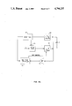
- the circuit in FIG. 4 includes the following components: A pulse rate timer 20 controls the system cycle rate and keeps the system synchronized by providing timing for the positive pulses, the negative pulse delay, and the negative pulse amplitude blocks.
- the positive pulse driver 22 is actually a circuit that provides electrical current to the transducer T to create a positive pulse while the negative pulse driver 24 creates the negative pulse.
- a delay timer 26 controls the timing of the negative pulse driver 24.
- a negative pulse controller 28 receives the incoming acoustic reverberations through an amplifier 30 and then controls the amplitude of the negative pulses by measuring and storing the amplitude of each reverberation for each positive pulse. It also controls the delay timer 26. How the amplitude is controlled and how the delay time ( ⁇ t) is controlled will be described in detail below.
- the system operates as follows.
- the positive pulse driver 22 causes a pulse of acoustic energy to be transmitted and the acoustic reverberations are received through the amplifier 30 to the pulse controller 28.
- the detection of the first acoustic reverberation is used to set the time delay ( ⁇ t) for the delay timer 26, as well as the amplitude of the negative pulses.
- the amplitude and the time delay ( ⁇ t) values are adjusted dynamically to drive the reverberations to a minimum, and the amplitude control can be approached in two methods.
- the amplitude of the negative pulses can be started at 0 and increases to a minimum value that will drive the acoustic reverberations to a null.
- the other method which is preferred, is to use the first acoustic reverberation to estimate the amplitude setting.
- the first reverberation is then driven to a null by varying upon the receipt of each reverberation the cancellation amplitude and the time delay so that the minimum reverberation level is dynamically achieved.
- the present invention can be established as hardwired, analog circuitry; however, software used with a programmable digital computer, and support hardware can accomplish equivalent results.
- the digital method can be described broadly as receiving the signal including the desired reflection and the acoustic reverberations, storing the signal, scaling the amplitude of the acoustic reverberations to the amplitude of the original signal's acoustic reverberations but delayed a time ( ⁇ t), and subtracting the processed signal from the stored original signal to produce a signal from which the acoustic reverberations have been removed.
- FIG. 4B One embodiment that uses the above described digital method is shown in FIG. 4B wherein a digital pulse driver 40 causes a pulse of electrical current to pass to the transducer T a predetermined timing sequence as determined by a rate timer 42.
- the signal receiver at the transducer T is first amplified by amplifier 44 and then converted to digital form in an analog/digital converter 46.
- the digital signal is then sent to a delay timer 48, a controller 50, such as a microprocessor, and into memory 52 such as RAM, associated with the controller 50.
- An amplifier scaler 54 scales the amplitude of the stored signal to be equal to the amplitude of the original series of reverberations.
- the delay timer 48 delays the original, unaltered received signal by a time corresponding to the time between acoustic reverberations within the layer and then the processed signal from the scaler 54 and the original signal from the delay timer 48 are combined to produce a signal that contains only the desired reflections, which is provided to an imaging device, such as a CRT, oscilloscope, or hardcopy generator.
- an imaging device such as a CRT, oscilloscope, or hardcopy generator.
- the two dynamic variables used in the present invention are the measurement of the rate of decay of the amplitude of the acoustic reverberations and the measurement of the appropriate time delay.
- the measurement of the amplitude of the signals can be accomplished by analog circuits such as peak and hold circuits or by using software in a digital computer.
- the measurement of the appropriate time delay can be accomplished by one of several open loop methods or by a signal derived method. Both methods can be analog or digital as needed.
- the first open loop method the first positive pulse of acoustic energy is transmitted and the resulting acoustic reverberations are received.
- the time of the firing of the acoustic transducer and the reception of the first acoustic reverberation is recorded and subtracted or separately counted to determine the first time delay ( ⁇ t).
- a negative pulse of acoustic energy is transmitted having an amplitude of the immediately preceding received acoustic reverberation and is adjusted dynamically as described above.
- the firing of the negative pulse is a time ⁇ t later than the firing of a second positive pulse, and ⁇ t is adjusted manually by the operator to achieve the best signal-to-noise ratio by visually reviewing the images.
- Another open loop method of determining ⁇ t uses alternating cycles wherein on the first cycle, a positive pulse of acoustic energy to transmitted and a measurement is made from the acoustic reverberations to determine ⁇ t.
- a second positive pulse of acoustic energy is transmitted and at a ⁇ t later than the second positive pulses' transmission, the appropriate negative pulse is transmitted at the time of each reception of the acoustic reverberations.
- a signal derived method for controlling the timed cancellation pulses is shown in FIG. 5.
- a timer 60 is used as a system clock and a positive pulse generator 62A causes a series of positive acoustic pulses to be transmitted from a transducer T.
- the receiver signal is conditioned in a signal conditioner 64 which provides amplification and, if needed, analog to digital conversion.
- a pulse delay block 66 has a timing delay which is the anticipated mean delay for a medium, such as the casing. This delay is adjusted by the operator or is updated dynamically after each repetitive pulse in the following manner.
- the transducer T output is approximated by a time shifted series of exponentially decaying sinusoids.
Abstract
Disclosed herein are methods for canceling acoustic reverberations caused when acoustic energy impinges a medium. In one method, a series of positive pulses of acoustic energy are transmitted and the amplitudes of the resulting acoustic reverberations are measured. Negative pulses of acoustic energy are then transmitted having amplitudes equal to the immediately preceding received acoustic reverberation and at a time later than the positive pulses so that the acoustic reverberations are driven to a null.
Description
1. Field of the Invention
The present invention relates to a method for improving the signal-to-noise ratio of a signal and, more particularly, to such a method for removing acoustic reverberations from the received signal.
2. Setting of the Invention
When an acoustic transducer has an electrical current passing across it, the transducer material will expand or contract to generate a positive or negative respectively pulse of acoustic energy. The acoustic energy passes through the surrounding environment and portions of the acoustic energy will be reflected back to the transducer upon contacting boundaries between disparate mediums. A problem exists where the acoustic energy contacts a relatively thin boundary layer between two disparate mediums, because of the `ringing` caused by closely spaced reverberations within the layer. The magnitude and time duration of the ringing is such that reflections from other outer boundaries can be totally obscured, that is, the ratio of the signal desired to be investigated to the ringing from the thin layer is considered so poor as rendering an analysis of the signal ineffective. An example of this problem will be described below.
In the art of oil and gas production from a wellbore, ultrasonic transducers in contact with the well casing can be used to investigate the quality of the cement bond between the column of cement surrounding a casing set within a wellbore. This tool utilizes one or more acoustic energy transducers to transmit acoustic energy pulses that pass through the casing, cement, and the surrounding formation. The acoustic reflections are received within the tool to produce a signal for analysis by an operator at the surface. The acoustic problem exists here because a thin, highly acoustically mismatched medium, i.e., the casing, exists between the transducer and the medium to be interrogated, i.e., the cement. As stated above, the casing causes ringing, and this ringing obscures the portions of the received signals of interest, such as reflections from cement defects interface and the cement-formation interface.
Various commonly known numerical methods can be used to improve the signal-to-noise ratio, such as those used by those skilled in the art in geophysics. These methods require the use of digital computers and cannot be practically implemented in a downhole well logging tool.
The present invention provides a method and related system for canceling acoustic reverberations caused when acoustic energy from a source, such as a transducer, impinges a layer, such as a casing. In the method, a positive acoustic pulse is transmitted, and the amplitudes of each of the resulting acoustic reverberations are measured. A negative acoustic pulse is transmitted with an ampitude equal to the immediately preceding received acoustic reverberation from the positive pulse. The time between the transmission of the positive acoustic pulse to the transmission of the negative acoustic pulse to cancel the effects of the acoustic reverberations is varied so that the negative acoustic pulses counteract or drive the acoustic reverberations to a null.
FIG. 1A is a cut away elevational view of an ultrasonic device, embodying the present invention, having a transducer placed in contact with a casing for identifying cement defects.
FIG. 1B is a signal amplitude vs time plot of a received signal from the transducer shown in FIG. 1A.
FIG. 2 is a diagrammatic representation of a series of positive acoustic reverberations and a corresponding series of negative acoustic pulses used to cancel the positive acoustic reverberations.
FIGS. 3A and 3B are diagrammatic representations of a series of acoustic pulses being reflected by casing and cement.
FIG. 4A is a circuit diagram of an analog embodiment of the present invention.
FIG. 4B is a circuit diagram of a digital embodiment of the present invention.
FIG. 5 is a circuit diagram of a digital system to adjust the time delay between the positive and the negative pulses.
The present invention provides a method and related system for canceling the effects of acoustic reverberations caused when acoustic energy from a source impinges a medium. In one embodiment of the method, a series of positive acoustic pulse is transmitted, and the amplitudes of each of the resulting acoustic reverberations are measured. A negative acoustic pulse is also transmitted with an amplitude equal to the immediately preceding received acoustic reverberation. The time between the transmission of a positive acoustic pulse to the transmission of a negative pulse (to cancel the effects of the acoustic reverberations) is varied so that the negative acoustic energy pulses counteract or drive the acoustic reverberations to a null. Even though acoustic pulses are bipolar, a positive pulse means herein a pulse of acoustic energy formed by an outward (expansion) initial pulse from a transducer, and a negative pulse means herein a pulse of acoustic energy formed by an inward (contraction) initial pulse from a transducer.
As shown in FIG. 1A, a transducer 10, carried on a wireline tool, is placed in contact with an interior surface of a casing 12 which is bonded via a column of cement 14 to a subterranean formation 16. The transducer 10 is preferably in direct contact with the casing 12, but can be spaced away therefrom, as is well-known to those skilled in the art. When an electrical current is provided to the transducer 10, a pulse of acoustic energy is transmitted outward through the casing 12 into the cement 14 and the formation 16. The acoustic reflections are received at the transducer 10 or another transducer (not shown), and the signal plot shown in Figure 1B illustrates the casing ringing which obscures the desired signal signal from the reflection of the casing-cement interface and the cement-formation interface.
The inventors hereof have found that if a transducer is fired to produce a positive pulse of acoustic energy on a predetermined timing sequence; i.e., every certain number of microseconds, the same or another transducer can be fired to produce negative pulses equal in amplitude to the received acoustic reverberations and having a time delay to drive the acoustic reverberations to a null. The inventors have found that if a positive pulse produces a waveform "+p" and a negative pulse produces a waveform "-p" which is approximately the negative of "+p", then because of superposition, the actual received waveform Σp="+p"+"-p" gives a waveform which has reduced reverberations and the reflection is not affected. As shown in FIG. 2, what is labeled as "+p" is a receiver signal amplitude vs time plot from each positive pulse of acoustic energy which includes the high amplitude, sharp pulse of acoustic energy followed by a series of reverberations, such as from casing ringing. The acoustic reverberations have a decreasing amplitude, called a ring-down effect, but maintain constant timing. Because of the casing ringing, the reflection of interest, such as the casing-cement-interface, is almost obscured.
What is labeled as "-p" is a signal amplitude vs time plot of a series of negative pulses of acoustic energy having a decreasing amplitude equal to the decreasing amplitude of the acoustic reverberations in "+p". Also, the time delay between the negative pulses of acoustic energy is equal to the timing of the acoustic reverberations from the positive pulses of acoustic energy. What is desired is for "-p" to be a generated mirror image of "+p," but without the initial positive pulse of acoustic energy and the reflection portion of the signal.
The inventors hereof have found that if "-p" is added to "+p" to be labeled "Σp" that what will remain is the desired reflection, i.e., the acoustic reverberations will have been cancelled or have been driven by the negative pulses to a null.
Another way to express the combination of the positive pulse reverberations with negative, opposite pulses is as follows and shown in FIGS. 3A and 3B. The waveform due to the positive pulse can be expressed as: ##EQU1## where: D1 is a constant proportional to the drive pulse amplitude
Ko is the reverberation constant which determines the rate of decay of the train of multiple echoes
P(t) is the waveform that would be received by the transducer from the casing/cement interface if no multiple echoes were present
τ is the time between multiple echoes and corresponds to the two way acoustic travel time across the casing
E(t) is the echo from an object beyond the casing.
The negative pulse is transmitted at t=τf and can be expressed by: ##EQU2## where: τf is the delay between positive pulse and negative pulse. The amplitude of the negative pulse is adjusted so that:
D.sub.2 =D.sub.1 K.sub.o (3)
τ.sub.f =τ
adding P1 (t) and P2 (t) ##EQU3## The Ko term in the second series is brought inside the summation to give Ko n+1 so that the n terms in the first series cancel the n+1 terms in the second series leaving
P.sub.1 (t)+P.sub.2 (t)=P(t)+E(t)-E(t-τ) (5)
FIG. 3A illustrates Equations (1)-(5). In actual practice, the E(t) signal generates a train of echoes when passing through the casing. But these echoes are cancelled in Equation (4) as shown in FIG. 3B. Note P(t) in (5) occurs at the same time as the negative firing pulse so can be ignored.
The removal of the acoustic reverberations can be achieved in an analog manner or in a digital manner, using hardwired circuitry or software. The primary need for the circuitry is to provide the ability to generate a negative acoustic pulse of appropriate amplitude and timing. The circuit in FIG. 4 includes the following components: A pulse rate timer 20 controls the system cycle rate and keeps the system synchronized by providing timing for the positive pulses, the negative pulse delay, and the negative pulse amplitude blocks. The positive pulse driver 22 is actually a circuit that provides electrical current to the transducer T to create a positive pulse while the negative pulse driver 24 creates the negative pulse. A delay timer 26 controls the timing of the negative pulse driver 24. A negative pulse controller 28 receives the incoming acoustic reverberations through an amplifier 30 and then controls the amplitude of the negative pulses by measuring and storing the amplitude of each reverberation for each positive pulse. It also controls the delay timer 26. How the amplitude is controlled and how the delay time (Δt) is controlled will be described in detail below. The system operates as follows. The positive pulse driver 22 causes a pulse of acoustic energy to be transmitted and the acoustic reverberations are received through the amplifier 30 to the pulse controller 28. The detection of the first acoustic reverberation is used to set the time delay (Δt) for the delay timer 26, as well as the amplitude of the negative pulses.
The amplitude and the time delay (Δt) values are adjusted dynamically to drive the reverberations to a minimum, and the amplitude control can be approached in two methods. In the first method, the amplitude of the negative pulses can be started at 0 and increases to a minimum value that will drive the acoustic reverberations to a null. The other method, which is preferred, is to use the first acoustic reverberation to estimate the amplitude setting. The first reverberation is then driven to a null by varying upon the receipt of each reverberation the cancellation amplitude and the time delay so that the minimum reverberation level is dynamically achieved. As previously discussed with reference to FIG. 3, the present invention can be established as hardwired, analog circuitry; however, software used with a programmable digital computer, and support hardware can accomplish equivalent results.
The digital method can be described broadly as receiving the signal including the desired reflection and the acoustic reverberations, storing the signal, scaling the amplitude of the acoustic reverberations to the amplitude of the original signal's acoustic reverberations but delayed a time (Δt), and subtracting the processed signal from the stored original signal to produce a signal from which the acoustic reverberations have been removed.
One embodiment that uses the above described digital method is shown in FIG. 4B wherein a digital pulse driver 40 causes a pulse of electrical current to pass to the transducer T a predetermined timing sequence as determined by a rate timer 42. The signal receiver at the transducer T is first amplified by amplifier 44 and then converted to digital form in an analog/digital converter 46. The digital signal is then sent to a delay timer 48, a controller 50, such as a microprocessor, and into memory 52 such as RAM, associated with the controller 50. An amplifier scaler 54 scales the amplitude of the stored signal to be equal to the amplitude of the original series of reverberations.
The delay timer 48 delays the original, unaltered received signal by a time corresponding to the time between acoustic reverberations within the layer and then the processed signal from the scaler 54 and the original signal from the delay timer 48 are combined to produce a signal that contains only the desired reflections, which is provided to an imaging device, such as a CRT, oscilloscope, or hardcopy generator.
The two dynamic variables used in the present invention are the measurement of the rate of decay of the amplitude of the acoustic reverberations and the measurement of the appropriate time delay. The measurement of the amplitude of the signals can be accomplished by analog circuits such as peak and hold circuits or by using software in a digital computer.
The measurement of the appropriate time delay can be accomplished by one of several open loop methods or by a signal derived method. Both methods can be analog or digital as needed. In the first open loop method, the first positive pulse of acoustic energy is transmitted and the resulting acoustic reverberations are received. The time of the firing of the acoustic transducer and the reception of the first acoustic reverberation is recorded and subtracted or separately counted to determine the first time delay (Δt). Thereafter, a negative pulse of acoustic energy is transmitted having an amplitude of the immediately preceding received acoustic reverberation and is adjusted dynamically as described above. The firing of the negative pulse is a time Δt later than the firing of a second positive pulse, and Δt is adjusted manually by the operator to achieve the best signal-to-noise ratio by visually reviewing the images.
Another open loop method of determining Δt uses alternating cycles wherein on the first cycle, a positive pulse of acoustic energy to transmitted and a measurement is made from the acoustic reverberations to determine Δt. A second positive pulse of acoustic energy is transmitted and at a Δt later than the second positive pulses' transmission, the appropriate negative pulse is transmitted at the time of each reception of the acoustic reverberations.
A signal derived method for controlling the timed cancellation pulses is shown in FIG. 5. A timer 60 is used as a system clock and a positive pulse generator 62A causes a series of positive acoustic pulses to be transmitted from a transducer T. The receiver signal is conditioned in a signal conditioner 64 which provides amplification and, if needed, analog to digital conversion. A pulse delay block 66 has a timing delay which is the anticipated mean delay for a medium, such as the casing. This delay is adjusted by the operator or is updated dynamically after each repetitive pulse in the following manner. The transducer T output is approximated by a time shifted series of exponentially decaying sinusoids.
Wherein the present invention has been described in particular relation to the drawings attached hereto, it should be understood that other and further modifications, apart from those shown and suggested herein, may be made within the scope and spirit of the present invention.
Claims (7)
1. A downhole tool for use in determining the presence of defects in cement surrounding a casing set within a wellbore, comprising:
a tool body adpated for suspension within the casing;
an acoustic energy transmitting transducer carried by the tool body for transmitting positive pulses of acoustic energy;
means carried by the tool body for receiving acoustic energy reverberations;
means for measuring the time delay, Δt, between the transmission of a pulse of acoustic energy and the reception of the first acoustic reverberation;
means for measuring the amplitude of the received acoustic reverberations, and
means carried on the tool for transmitting a series of negative pulses of acoustic energy at a time, Δt, later than the transmission of each positive pulse of acoustic energy, and each having an amplitude equal to the measured amplitude of the immediately preceding received acoustic reverberation.
2. A method of enhancing the signal-to-noise ratio from a cement defect identification tool by cancelling the casing reverberation noise comprising:
placing an acoustic energy transducer against the interior surface of a casing set within cement in a wellbore;
transmitting a series of positive acoustic pulses, at a constant timing sequence, from the acoustic energy transducer;
receiving an acoustic signal comprising a reflection of the casing-cement interface and casing reverberation noise;
measuring the amplitude of each received casing reverberation noise portion of the acoustic signal;
transmitting a series of negative acoustic pulses each having an amplitude equal to the immediately preceding received casing reverberation noise portion of the acoustic signal; and
varying the time delay between the transmission of a positive acoustic pulse to the transmission of the negative pulses to cancel casing reverberation noise.
3. A method of enhancing the signal-to-noise ratio from a cement defect identification tool by canceling casing reverberation noise, comprising:
(a) placing an acoustic energy transducer against the interior surface of a casing set within cement in a wellbore;
(b) transmitting a pulse of acoustic energy from the acoustic energy transducer;
(c) receiving an acoustic signal comprising a reflection of the casing-cement interface and casing reverberation noise;
(d) storing a digital form of the acoustical signal;
(e) scaling the amplitude of the acoustic signal delayed a time (Δt) between the transmission of the pulse of acoustic energy and the reception of the acoustic signal; and
(f) subtracting the scaled acoustic signal from the stored acoustic signal to generate a refined signal from which casing reverberation noise has been removed.
4. A method of claim 3 wherein step (e) includes multiplying the casing reverberation noise by a scaler constant K, wherein K is greater than or equal to one.
5. A system for enhancing the signal-to-noise ratio from a cement defect identification tool by canceling casing reverberation noise, comprising:
(a) an acoustic energy transducer carried on a tool adapted for suspension within a wellbore casing, the transducer placable against the interior surface of the casing set within cement in a wellbore;
(b) means for transmitting a pulse of acoustic energy from the acoustic energy transducer;
(c) means for receiving an acoustic signal comprising a reflection of a casing-cement interface and casing reverberation noise;
(d) means for storing a digital form of the acoustic signal;
(e) means for scaling the amplitude of the acoustic signal delayed at time (Δt) between the transmission of the pulse of acoustic energy and the reception of the acoustic signal; and
(f) means for subtracting the scaled acoustic signal from the stored acoustic signal to generate a refined signal from which casing reverberation noise has been removed.
6. The system of claim 5 wherein the means for scaling the amplitude of the acoustic signal includes means for multiplying the casing reverberation noise by a scaler constant K, wherein K is greater than or equal to one.
7. A method of enhancing the signal-to-noise ratio from a cement defect identification tool by canceling casing reverberation noise, comprising:
(a) placing an acoustic energy transducer against the interior surface of a casing set within cement in a wellbore;
(b) transmitting at least one positive acoustic pulse from the acoustic energy transducer;
(c) receiving an acoustic signal comprising a reflection of the casing-cement interface and casing reverberation noise;
(d) measuring the amplitude of the received casing reverberation noise portion of the acoustic signal;
(e) transmitting a least one negative acoustic pulse having an amplitude equal to the received casing reverberation noise portion of the acoustic signal; and
(f) varying the time delay between transmission of the positive acoustic pulse to transmission of the negative acoustic pulse to cancel casing reverberation noise.
Priority Applications (2)
| Application Number | Priority Date | Filing Date | Title |
|---|---|---|---|
| US07/008,015 US4796237A (en) | 1987-01-28 | 1987-01-28 | Method for acoustic reverberation removal |
| CA000554323A CA1295043C (en) | 1987-01-28 | 1987-12-15 | Method for acoustic reverberation removal |
Applications Claiming Priority (1)
| Application Number | Priority Date | Filing Date | Title |
|---|---|---|---|
| US07/008,015 US4796237A (en) | 1987-01-28 | 1987-01-28 | Method for acoustic reverberation removal |
Publications (1)
| Publication Number | Publication Date |
|---|---|
| US4796237A true US4796237A (en) | 1989-01-03 |
Family
ID=21729359
Family Applications (1)
| Application Number | Title | Priority Date | Filing Date |
|---|---|---|---|
| US07/008,015 Expired - Fee Related US4796237A (en) | 1987-01-28 | 1987-01-28 | Method for acoustic reverberation removal |
Country Status (2)
| Country | Link |
|---|---|
| US (1) | US4796237A (en) |
| CA (1) | CA1295043C (en) |
Cited By (21)
| Publication number | Priority date | Publication date | Assignee | Title |
|---|---|---|---|---|
| EP0541856A1 (en) * | 1991-11-15 | 1993-05-19 | Siemens Aktiengesellschaft | Method and apparatus for suppressing reflections on a ultrasonic transducer |
| US5274604A (en) * | 1992-10-13 | 1993-12-28 | Schlumberger Technology Corporation | Method for spatially filtering signals representing formation and channel echoes in a borehole environment |
| US5886303A (en) * | 1997-10-20 | 1999-03-23 | Dresser Industries, Inc. | Method and apparatus for cancellation of unwanted signals in MWD acoustic tools |
| US5987385A (en) * | 1997-08-29 | 1999-11-16 | Dresser Industries, Inc. | Method and apparatus for creating an image of an earth borehole or a well casing |
| US20020149499A1 (en) * | 1999-02-19 | 2002-10-17 | Dresser Industries, Inc. | Casing mounted sensors, actuators and generators |
| GB2392577A (en) * | 2002-08-26 | 2004-03-03 | Schlumberger Holdings | Active reduction of tool borne noise in a sonic logging tool |
| US20070280049A1 (en) * | 2006-05-31 | 2007-12-06 | Baker Hughes Incorporated | Active noise cancellation through the use of magnetic coupling |
| US20080300869A1 (en) * | 2004-07-22 | 2008-12-04 | Koninklijke Philips Electronics, N.V. | Audio Signal Dereverberation |
| US20100265796A1 (en) * | 2009-04-21 | 2010-10-21 | Baker Hughes Incorporated | Televiewer Image Wood-Grain Reduction Techniques |
| WO2011127156A2 (en) * | 2010-04-07 | 2011-10-13 | Baker Hughes Incorporated | Method and apparatus for evaluating a cemented borehole casing |
| US20130310689A1 (en) * | 2011-08-31 | 2013-11-21 | Panasonic Corporation | Ultrasound diagnostic device |
| GB2514252A (en) * | 2013-03-26 | 2014-11-19 | Bosch Gmbh Robert | Apparatus for surround-field sensorics and process for adapating a dynamic range of a receiving amplifier |
| WO2015094939A1 (en) * | 2013-12-19 | 2015-06-25 | Services Petroliers Schlumberger | Vibration control for a cement evaluation tool |
| US20160033663A1 (en) * | 2014-02-20 | 2016-02-04 | Halliburton Energy Services, Inc. | Control of Acoustic Transmitters for Downhole Measurement or Logging |
| US20160178779A1 (en) * | 2014-12-17 | 2016-06-23 | Schlumberger Technology Corporation | System and Methods for Removing Noise From Acoustic Impedance Logs |
| EP3149274A4 (en) * | 2014-08-07 | 2018-02-28 | Halliburton Energy Services, Inc. | Active dampening for a wellbore logging tool using iterative learning techniques |
| US20180160226A1 (en) * | 2016-12-05 | 2018-06-07 | Semiconductor Components Industries, Llc | Reducing or eliminating transducer reverberation |
| CN110792429A (en) * | 2019-11-04 | 2020-02-14 | 中国石油集团川庆钻探工程有限公司 | Method for encoding downhole data by simultaneously utilizing positive and negative pressure pulses and transmission method |
| US10809406B2 (en) * | 2014-08-07 | 2020-10-20 | Halliburton Energy Services, Inc. | Online active vibration control for a wellbore logging tool |
| WO2021006948A1 (en) * | 2019-07-11 | 2021-01-14 | Halliburton Energy Services, Inc. | Fiber optic noise mitigation for distributed acoustic sensing |
| US20210349229A1 (en) * | 2019-01-14 | 2021-11-11 | Halliburton Energy Services, Inc. | Reduction of a tool wave excited by a transmitter of a well logging tool |
Citations (3)
| Publication number | Priority date | Publication date | Assignee | Title |
|---|---|---|---|---|
| US3326320A (en) * | 1964-12-31 | 1967-06-20 | Pan American Petroleum Corp | Seismic surveying with an impulse pattern consisting of positive and negative impulses |
| US4382290A (en) * | 1977-07-11 | 1983-05-03 | Schlumberger Technology Corporation | Apparatus for acoustically investigating a borehole |
| US4644508A (en) * | 1983-12-28 | 1987-02-17 | Mobil Oil Corporation | Method and apparatus for selectively reinforcing detected seismic waves |
-
1987
- 1987-01-28 US US07/008,015 patent/US4796237A/en not_active Expired - Fee Related
- 1987-12-15 CA CA000554323A patent/CA1295043C/en not_active Expired - Fee Related
Patent Citations (3)
| Publication number | Priority date | Publication date | Assignee | Title |
|---|---|---|---|---|
| US3326320A (en) * | 1964-12-31 | 1967-06-20 | Pan American Petroleum Corp | Seismic surveying with an impulse pattern consisting of positive and negative impulses |
| US4382290A (en) * | 1977-07-11 | 1983-05-03 | Schlumberger Technology Corporation | Apparatus for acoustically investigating a borehole |
| US4644508A (en) * | 1983-12-28 | 1987-02-17 | Mobil Oil Corporation | Method and apparatus for selectively reinforcing detected seismic waves |
Cited By (51)
| Publication number | Priority date | Publication date | Assignee | Title |
|---|---|---|---|---|
| EP0541856A1 (en) * | 1991-11-15 | 1993-05-19 | Siemens Aktiengesellschaft | Method and apparatus for suppressing reflections on a ultrasonic transducer |
| US5245586A (en) * | 1991-11-15 | 1993-09-14 | Siemens Aktiengesellschaft | Apparatus and method for suppressing reflections at an ultrasound transducer |
| US5274604A (en) * | 1992-10-13 | 1993-12-28 | Schlumberger Technology Corporation | Method for spatially filtering signals representing formation and channel echoes in a borehole environment |
| US5987385A (en) * | 1997-08-29 | 1999-11-16 | Dresser Industries, Inc. | Method and apparatus for creating an image of an earth borehole or a well casing |
| US5886303A (en) * | 1997-10-20 | 1999-03-23 | Dresser Industries, Inc. | Method and apparatus for cancellation of unwanted signals in MWD acoustic tools |
| US7173542B2 (en) | 1999-02-19 | 2007-02-06 | Halliburton Energy Services, Inc. | Data relay for casing mounted sensors, actuators and generators |
| US20070139217A1 (en) * | 1999-02-19 | 2007-06-21 | Halliburton Energy Services, Inc., A Delaware Corp | Data relay system for casing mounted sensors, actuators and generators |
| US7932834B2 (en) | 1999-02-19 | 2011-04-26 | Halliburton Energy Services. Inc. | Data relay system for instrument and controller attached to a drill string |
| US20020149499A1 (en) * | 1999-02-19 | 2002-10-17 | Dresser Industries, Inc. | Casing mounted sensors, actuators and generators |
| US7046165B2 (en) * | 1999-02-19 | 2006-05-16 | Halliburton Energy Services, Inc. | Method for collecting geological data ahead of a drill bit |
| US20020154027A1 (en) * | 1999-02-19 | 2002-10-24 | Dresser Industries, Inc. | Casing mounted sensors, actuators and generators |
| US20070132605A1 (en) * | 1999-02-19 | 2007-06-14 | Halliburton Energy Services, Inc., A Delaware Corporation | Casing mounted sensors, actuators and generators |
| GB2392577B (en) * | 2002-08-26 | 2004-10-20 | Schlumberger Holdings | Active reduction of tool borne noise in a sonic logging tool |
| GB2392577A (en) * | 2002-08-26 | 2004-03-03 | Schlumberger Holdings | Active reduction of tool borne noise in a sonic logging tool |
| US20080300869A1 (en) * | 2004-07-22 | 2008-12-04 | Koninklijke Philips Electronics, N.V. | Audio Signal Dereverberation |
| US8116471B2 (en) * | 2004-07-22 | 2012-02-14 | Koninklijke Philips Electronics, N.V. | Audio signal dereverberation |
| US7911877B2 (en) | 2006-05-31 | 2011-03-22 | Baker Hughes Incorporated | Active noise cancellation through the use of magnetic coupling |
| US20070280049A1 (en) * | 2006-05-31 | 2007-12-06 | Baker Hughes Incorporated | Active noise cancellation through the use of magnetic coupling |
| US7639562B2 (en) * | 2006-05-31 | 2009-12-29 | Baker Hughes Incorporated | Active noise cancellation through the use of magnetic coupling |
| US20100097887A1 (en) * | 2006-05-31 | 2010-04-22 | Baker Hughes Incorporated | Active Noise Cancellation Through the Use of Magnetic Coupling |
| GB2481350A (en) * | 2009-04-21 | 2011-12-21 | Baker Hughes Inc | Televiewer image wood-grain reduction techniques |
| US8634272B2 (en) | 2009-04-21 | 2014-01-21 | Baker Hughes Incorporated | Televiewer image wood-grain reduction techniques |
| WO2010123746A3 (en) * | 2009-04-21 | 2011-01-20 | Baker Hughes Incorporated | Televiewer image wood-grain reduction techniques |
| WO2010123746A2 (en) * | 2009-04-21 | 2010-10-28 | Baker Hughes Incorporated | Televiewer image wood-grain reduction techniques |
| US20100265796A1 (en) * | 2009-04-21 | 2010-10-21 | Baker Hughes Incorporated | Televiewer Image Wood-Grain Reduction Techniques |
| US8913461B2 (en) | 2009-04-21 | 2014-12-16 | Baker Hughes Incorporated | Televiewer image wood-grain reduction techniques |
| GB2481350B (en) * | 2009-04-21 | 2014-01-29 | Baker Hughes Inc | Televiewer image wood-grain reduction techniques |
| WO2011127156A3 (en) * | 2010-04-07 | 2012-04-05 | Baker Hughes Incorporated | Method and apparatus for evaluating a cemented borehole casing |
| GB2492693A (en) * | 2010-04-07 | 2013-01-09 | Baker Hughes Inc | Method and apparatus for evaluating a cemented borehole casing |
| US8964504B2 (en) | 2010-04-07 | 2015-02-24 | Baker Hughes Incorporated | Method and apparatus for evaluating a cemented borehole casing |
| GB2492693B (en) * | 2010-04-07 | 2015-05-20 | Baker Hughes Inc | Method and apparatus for evaluating a cemented borehole casing |
| WO2011127156A2 (en) * | 2010-04-07 | 2011-10-13 | Baker Hughes Incorporated | Method and apparatus for evaluating a cemented borehole casing |
| US20130310689A1 (en) * | 2011-08-31 | 2013-11-21 | Panasonic Corporation | Ultrasound diagnostic device |
| GB2514252A (en) * | 2013-03-26 | 2014-11-19 | Bosch Gmbh Robert | Apparatus for surround-field sensorics and process for adapating a dynamic range of a receiving amplifier |
| GB2514252B (en) * | 2013-03-26 | 2019-07-17 | Bosch Gmbh Robert | Apparatus for surround-field sensorics and process for adapting a dynamic range of a receiving amplifier |
| US10101483B2 (en) | 2013-12-19 | 2018-10-16 | Schlumberger Technology Corporation | Vibration control for a cement evaluation tool |
| WO2015094939A1 (en) * | 2013-12-19 | 2015-06-25 | Services Petroliers Schlumberger | Vibration control for a cement evaluation tool |
| US20160033663A1 (en) * | 2014-02-20 | 2016-02-04 | Halliburton Energy Services, Inc. | Control of Acoustic Transmitters for Downhole Measurement or Logging |
| US10401521B2 (en) * | 2014-02-20 | 2019-09-03 | Halliburton Energy Services, Inc. | Control of acoustic transmitters for downhole measurement or logging |
| US10809406B2 (en) * | 2014-08-07 | 2020-10-20 | Halliburton Energy Services, Inc. | Online active vibration control for a wellbore logging tool |
| EP3149274A4 (en) * | 2014-08-07 | 2018-02-28 | Halliburton Energy Services, Inc. | Active dampening for a wellbore logging tool using iterative learning techniques |
| US9945975B2 (en) * | 2014-08-07 | 2018-04-17 | Halliburton Energy Services, Inc. | Active dampening for a wellbore logging tool using iterative learning techniques |
| US20160178779A1 (en) * | 2014-12-17 | 2016-06-23 | Schlumberger Technology Corporation | System and Methods for Removing Noise From Acoustic Impedance Logs |
| US10871589B2 (en) * | 2014-12-17 | 2020-12-22 | Schlumberger Technology Corporation | System and methods for removing noise from acoustic impedance logs |
| US20180160226A1 (en) * | 2016-12-05 | 2018-06-07 | Semiconductor Components Industries, Llc | Reducing or eliminating transducer reverberation |
| US20200413188A1 (en) * | 2016-12-05 | 2020-12-31 | Semiconductor Components Industries, Llc | Reducing or eliminating transducer reverberation |
| US20210349229A1 (en) * | 2019-01-14 | 2021-11-11 | Halliburton Energy Services, Inc. | Reduction of a tool wave excited by a transmitter of a well logging tool |
| US11774619B2 (en) * | 2019-01-14 | 2023-10-03 | Halliburton Energy Services, Inc. | Reduction of a tool wave excited by a transmitter of a well logging tool |
| WO2021006948A1 (en) * | 2019-07-11 | 2021-01-14 | Halliburton Energy Services, Inc. | Fiber optic noise mitigation for distributed acoustic sensing |
| US11340371B2 (en) | 2019-07-11 | 2022-05-24 | Halliburton Energy Services, Inc. | Fiber optic noise mitigation for distributed acoustic sensing |
| CN110792429A (en) * | 2019-11-04 | 2020-02-14 | 中国石油集团川庆钻探工程有限公司 | Method for encoding downhole data by simultaneously utilizing positive and negative pressure pulses and transmission method |
Also Published As
| Publication number | Publication date |
|---|---|
| CA1295043C (en) | 1992-01-28 |
Similar Documents
| Publication | Publication Date | Title |
|---|---|---|
| US4796237A (en) | Method for acoustic reverberation removal | |
| US6335905B1 (en) | Method for elimination of passive noise interference in sonar | |
| WO2004023158A8 (en) | System and method for improved harmonic imaging | |
| EP0920832A3 (en) | Ultrasonic densitometer device and method | |
| US4796238A (en) | System for measurement of the acoustic coefficient of reflection of submerged reflectors | |
| AU6925294A (en) | Method and device for the non-destructive testing of objects using ultrasonics | |
| JPS6171379A (en) | Device and method of discriminating electric signal | |
| US4520670A (en) | Method and apparatus for generating short ultrasonic echo pulses | |
| ATE93065T1 (en) | METHOD OF SUPPRESSING NOISE SIGNALS DURING THE OPERATION OF ULTRASONIC PROXIMITY INITIATORS. | |
| GB2002902A (en) | Method and apparatus for acoustically investigating a casing and casing cement bond in a borehole penetrating an earth formation | |
| US4056971A (en) | Distance amplitude compensation system | |
| US4228688A (en) | Accurate distance amplitude compensation | |
| US4446540A (en) | Acoustic well logging with energy level detection | |
| JPH0552461B2 (en) | ||
| JPH045159B2 (en) | ||
| JPH0616113B2 (en) | Method and apparatus for determining long range characteristics of signals from seismic signal source assemblies | |
| ATE283496T1 (en) | METHOD AND DEVICE FOR VISIBILIZING ULTRASOUND | |
| US5515339A (en) | Ultrasonic transmitting-receiving apparatus | |
| JP2648605B2 (en) | Underwater detector | |
| JPH036471B2 (en) | ||
| GB2100431A (en) | Detection of ultrasonic signals from disturbed liquid interfaces or surfaces | |
| JP2728265B2 (en) | Equipment for measuring the thickness of objects with coatings | |
| GB1109443A (en) | Echo-sounding apparatus for examining strata below the sea-bed | |
| SU966586A1 (en) | Method of quality control of with aid acoustic emission dielectric material made apparatus | |
| JPH0774825B2 (en) | Underwater detector |
Legal Events
| Date | Code | Title | Description |
|---|---|---|---|
| AS | Assignment |
Owner name: AMOCO CORPORATION (FORMERLY STANDARD OIL COMPANY), Free format text: ASSIGNMENT OF ASSIGNORS INTEREST.;ASSIGNORS:HUTCHENS, CHRISWELL G.;MORRIS, STEVEN A.;REEL/FRAME:004694/0885;SIGNING DATES FROM 19870126 TO 19870128 |
|
| LAPS | Lapse for failure to pay maintenance fees | ||
| FP | Lapsed due to failure to pay maintenance fee |
Effective date: 19930103 |
|
| STCH | Information on status: patent discontinuation |
Free format text: PATENT EXPIRED DUE TO NONPAYMENT OF MAINTENANCE FEES UNDER 37 CFR 1.362 |