US4793765A - Material handling apparatus - Google Patents
Material handling apparatus Download PDFInfo
- Publication number
- US4793765A US4793765A US07/091,180 US9118087A US4793765A US 4793765 A US4793765 A US 4793765A US 9118087 A US9118087 A US 9118087A US 4793765 A US4793765 A US 4793765A
- Authority
- US
- United States
- Prior art keywords
- support
- inner member
- slot
- outer member
- adjacent
- Prior art date
- Legal status (The legal status is an assumption and is not a legal conclusion. Google has not performed a legal analysis and makes no representation as to the accuracy of the status listed.)
- Expired - Fee Related
Links
Images


Classifications
-
- E—FIXED CONSTRUCTIONS
- E02—HYDRAULIC ENGINEERING; FOUNDATIONS; SOIL SHIFTING
- E02F—DREDGING; SOIL-SHIFTING
- E02F3/00—Dredgers; Soil-shifting machines
- E02F3/04—Dredgers; Soil-shifting machines mechanically-driven
- E02F3/28—Dredgers; Soil-shifting machines mechanically-driven with digging tools mounted on a dipper- or bucket-arm, i.e. there is either one arm or a pair of arms, e.g. dippers, buckets
- E02F3/30—Dredgers; Soil-shifting machines mechanically-driven with digging tools mounted on a dipper- or bucket-arm, i.e. there is either one arm or a pair of arms, e.g. dippers, buckets with a dipper-arm pivoted on a cantilever beam, i.e. boom
- E02F3/306—Dredgers; Soil-shifting machines mechanically-driven with digging tools mounted on a dipper- or bucket-arm, i.e. there is either one arm or a pair of arms, e.g. dippers, buckets with a dipper-arm pivoted on a cantilever beam, i.e. boom with telescopic dipper-arm or boom
Definitions
- This invention relates to material handling apparatus which employs an extendable arm in which an inner arm member can be slid relative to an outer encircling arm member to vary the effective length and thus the reach of the arm.
- an extendable material handling arm comprising an outer member having a slot extending along the length thereof, an inner member provided with material handling means adjacent one end, the inner member being encircled by the outer member for sliding therein to vary the effective length of the arm, a first support structure carried by the inner member adjacent the end thereof remote from the material handling means, the first support structure including a support means having a support surface for sliding contact with longitudinally extending portions of the outer surface of the outer member adjacent the slot, and securing means extending through said slot for securing the support means to the inner member for sliding movement therewith so that said remote end of the inner member is supported within said outer member by holding said portions of the outer member adjacent the slot between said support means support surface and a support surface on the inner member and clearance is left between the inner and outer members along side portions opposite and remote from the slot.
- the outer member is of generally rectangular cross-section with the slot extending longitudinally down one side of the outer member the first support structure will pull the inner member into contact with the slotted side of the outer leaving clearance between the inner and outer members along their sides opposite the slot. This clearance will be present along substantially the entire length of the inner member within the outer member.
- a second support structure is provided for sliding support of the inner member within the outer member at a location adjacent the end of the outer member nearest the material handling means so that direct contact between the inner and outer members is also avoided at this location.
- Wear can be reduced still further by providing one or both support structures with low friction support surfaces made, for example, from self-lubricating cast nylon oil-impregnated material such as "Nylacast Oilon” sold by Nylacast Oilon Limited of Leicester, United Kingdom. If such an oil impregnated material is used, no lubrication of the sliding contact between the inner and outer members is necessary.
- self-lubricating cast nylon oil-impregnated material such as "Nylacast Oilon” sold by Nylacast Oilon Limited of Leicester, United Kingdom. If such an oil impregnated material is used, no lubrication of the sliding contact between the inner and outer members is necessary.
- the first support structure supports the inner member against transverse movement within the outer member in directions at right angles to the direction of extent of the securing means.
- This transverse support is also preferably provided by surfaces of low friction material on the inner member for contact with the inner surface of the outer member.
- the second support structure preferably comprises a collar on the outer member, the collar encircling the inner member and supporting detachable low friction wear pads which contact the outer surface of the inner member.
- the areas of sliding contact between the support surface and the outer member are preferably disposed outwardly away from the slot to reduce any bending moment imposed on the outer member from the inner member via the first support structure.
- the invention also provides a dipper stick for a backhoe in the form of an extendable arm as described above.
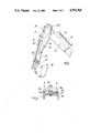
- FIG. 1 is a side view of part of the digger
- FIG. 2 is a side view of the dipper stick of FIG. 1 in more detail
- FIG. 3 is a top view of the dipper stick of FIG. 2;
- FIG. 4 is a sectional view on line x--x of FIG. 2;
- FIG. 5 is an exploded view in the direction of arrow Y of FIG. 2;
- FIG. 6 is a view in the direction of arrow Z of FIG. 2;
- FIG. 7 is a diagrammatic representation of part of the section of FIG. 4, and
- FIG. 8 is a diagrammatic representation, corresponding to FIG. 4, of part of an alternative support structure arrangement.
- FIG. 1 shows part of a backhoe digger in which an extendable dipper stick 10 is pivotted at 11 on a digger boom 12.
- the boom 12 can be raised and lowered by an hydraulic actuator 13 and the dipper stick can be pivotted relative to the boom by an hydraulic actuator 14.
- the dipper stick has a hollow square cross-section outer member 15 with reinforcing side plates 16 which provide the pivotal mounting 11 and also the mounting point 14a for actuator 14.
- a dipper stick inner member 17 is slidable in outer member 15 and carries at its lower end a bucket 18.
- the inner and outer dipper stick members 17 and 15 are arranged to be moved relative to each other by an hydraulic actuator 19 which acts between these members and is disposed inside the inner member 17.
- the upper face of the outer member 15 of the dipper stick is provided with a longitudinally extending slot 20.
- the inner dipper stick member 17 carries a mounting member 21 for bucket actuator 22. This mounting member extends through slot 20 and is moved along this slot as the inner and outer dipper stick members are moved relative to each other by actuator 19.
- the inner dipper stick member 17 is supported within the outer member 15 by a first support structure 24 carried on the inner member adjacent the end remote from a bucket 18 and by a second support structure 23 which is located at the end of the outer member nearest to the bucket 18.
- this comprises a collar 25 which is welded to the end of dipper stick outer member 15.
- the collar itself is of a welded construction and is provided with a slot 26 in its upper surface which acts as a continuation of slot 20 to allow the passage of outer member 21 during assembly of the dipper stick.
- the side 25a of the collar is provided with an open-fronted recess 27 (shown in dotted detail in FIG. 6) which receives a wear pad 28 of self-lubricating cast nylon oil-impregnated material (for example "Nylacast Oilon" referred to above). Wear pad 28 is retained in the recess 27 by a scraper plate 29 which is bolted at 29a to the end of side 25a of the collar.
- a similarly shaped open-fronted recess 30 is providing the slotted side 25b of the collar. This recess houses a wear pad 31 which is retained by a keeper plate 32 which overlies the side 25b and is retained by bolts 32a.
- the remaining sides 25c and 25d of the dipper outer are each provided with a pair of wear pads 33, each supported in a recessed backing member 34 which is bolted to the collar by bolts 35.
- the wear pads 28 and 33 are adjusted by the use of appropriate shims to ensure that minimal clearance is present between the inner member 17 and each contacting wear pad so that the inner member 17, is closely guided and supported within the outer member 15. Typically, for example, up to a maximum of 1 mm total clearance is allowed on the fit between opposite pads 33.
- the first support structure 24 comprises a support means in the form of a plate 36 which is stiffened by welded webs 37 add which carries a wear pad 38 of self-lubricating cast nylon oil-impregnated material. This wear pad contacts the longitudinally extending portions of the outer surface of side 15b of outer member 15 along the edges of slot 20.
- the plate 36 is secured to the inner member of the dipper stick by a pair of studs 39, which extend through the slot 20. These studs are secured to that portion of the inner member 17 which are reinforced by a stiffening web 40, which extends from the end of the dipper remote from the bucket 18 to a location on the bucket side of the attachment point of mounting member 21.
- the side 17b of the inner member is provided with a wear pad 41 of self-lubricating cast nylon oil-impregnated material for contact with the longitudinally extending inner surface of the side 15b of outer member adjacent slot 20.
- Each stud is provided with two spacers, a spacer 42 disposed in the slot 20 and a spacer 43 under the nut 44 of the stud.
- this contact pressure is controlled to be at a very low level consistent with the accurate location and support of the inner member. Again, typically up to a maximum of 1 mm total clearance is allowed on the fit between pads 38 and 41.
- the first support structure draws the inner member into contact with the side 15b of the outer member, so that a clearance exists between the sides 15a and 17a of the outer and inner members respectively which are opposite and remote from the slot 20.
- the dipper stick is designed to have this clearance, less accurate control of the manufacture of the inner and outer members is necessary since the fit between these two members is not used to locate accurately the inner member within the outer member during use of the dipper stick.
- the first support structure also includes a pair of wear pads 45 each received in a recessed backing member 46. These backing members are welded to sides 17c and 17d respectively of the inner member. Wear pads 45 are of self-lubricating cast nylon oil-impregnated material and are not secured in the backing members 46 but are located in position during assembly by smearing the backing member recesses with grease. Tee contact pressure of pads 45 against the inner surface of the outer dipper stick member 15 is controlled by shims in the backing member recesses to be at a low level consistent with the required support and guidance of the inner member against transverse movement in directions D at right angles to the direction of constraint provided by the studs 39 and associated wear pads 38 and 41. Again typically up to a maximum of 1 mm total clearance is allowed on the fit between pads 45 and the outer member.
- FIG. 8 shows diagrammatically an alternative arrangement for transmitting the reaction load R to the outer member 15 at locations well spaced from the slot 20 to reduce the bending moment of the reaction load by forming the contact area between the support plate 36 and the side portions 15b of the outer member as strips 50 of self-lubricating cast nylon oil-impregnated material. These strips are located on the support plate adjacent to the sides 15c and 15d of the outer member. Using this alternative arrangement, control of the angle ⁇ of the side portions 15b, as described in relation to FIG. 7, is unnecessary.
- the present invention provides an extendable arm for a material handling apparatus such as the dipper stick of a backhoe digger, in which the inner member is located in the outer member by a support structure carried on the inner member at the end thereof remote from the material handling means in a manner which minimises the contact between the inner and outer members.
- the present invention also provides a construction in which the actual contact between the inner and outer members is provided by a number of wear pads which are of low friction material to minimise wear and which can all be replaced relatively quickly and easily, thus reducing maintenance costs.
Landscapes
- Engineering & Computer Science (AREA)
- Mechanical Engineering (AREA)
- Mining & Mineral Resources (AREA)
- Civil Engineering (AREA)
- General Engineering & Computer Science (AREA)
- Structural Engineering (AREA)
- Shovels (AREA)
- Pivots And Pivotal Connections (AREA)
Abstract
Description
Claims (9)
Applications Claiming Priority (2)
| Application Number | Priority Date | Filing Date | Title |
|---|---|---|---|
| GB8717654 | 1987-07-24 | ||
| GB8717654A GB2207117B (en) | 1987-07-24 | 1987-07-24 | Material handling apparatus |
Publications (1)
| Publication Number | Publication Date |
|---|---|
| US4793765A true US4793765A (en) | 1988-12-27 |
Family
ID=10621295
Family Applications (1)
| Application Number | Title | Priority Date | Filing Date |
|---|---|---|---|
| US07/091,180 Expired - Fee Related US4793765A (en) | 1987-07-24 | 1987-08-31 | Material handling apparatus |
Country Status (2)
| Country | Link |
|---|---|
| US (1) | US4793765A (en) |
| GB (1) | GB2207117B (en) |
Cited By (7)
| Publication number | Priority date | Publication date | Assignee | Title |
|---|---|---|---|---|
| US4919585A (en) * | 1989-09-05 | 1990-04-24 | Ruiz Peter L | Vehicular mounted excavator |
| US5092733A (en) * | 1989-04-26 | 1992-03-03 | Kabushiki Kaisha Hikoma Seisakusho | Tool controlling mechanisms for excavator with telescopic arm |
| US5267824A (en) * | 1989-04-26 | 1993-12-07 | Kabushiki Kaisha Japanic | Tool controlling mechanisms for excavator with telescopic arm |
| US20030194305A1 (en) * | 2002-04-15 | 2003-10-16 | Opitz Kary A. | Magnetic lifting system |
| US6726437B2 (en) | 2002-02-08 | 2004-04-27 | Clark Equipment Company | Telescoping loader lift arm |
| US20050045575A1 (en) * | 2003-09-01 | 2005-03-03 | Eckhard Wimmer | Crane |
| US20090263224A1 (en) * | 2002-12-04 | 2009-10-22 | Tygard Machine & Manufacturing Company | Clamping apparatus |
Families Citing this family (1)
| Publication number | Priority date | Publication date | Assignee | Title |
|---|---|---|---|---|
| FR2652599B1 (en) * | 1989-10-02 | 1992-11-13 | Souchon Maurice | MOTORIZED EARTHMOVING MACHINE WITH TELESCOPIC BOOM. |
Citations (6)
| Publication number | Priority date | Publication date | Assignee | Title |
|---|---|---|---|---|
| US2316389A (en) * | 1940-08-03 | 1943-04-13 | Earl B Atkinson | Adjustable bar hanger and receptacle fastening means |
| DE817363C (en) * | 1950-07-06 | 1951-10-18 | Josef Gehlen | Formwork for windowsill panels over niches |
| US2685876A (en) * | 1951-07-27 | 1954-08-10 | Arland J Sanderson | Support for wallpaper steamer |
| FR1254593A (en) * | 1960-02-24 | 1961-02-24 | Mating fishing rod sections | |
| US3337071A (en) * | 1966-01-03 | 1967-08-22 | Joseph C Clark | Selective controller for hydraulic actuators |
| US4604026A (en) * | 1983-03-01 | 1986-08-05 | Dart Industries Inc. | Telescoping parts manipulator |
-
1987
- 1987-07-24 GB GB8717654A patent/GB2207117B/en not_active Expired - Fee Related
- 1987-08-31 US US07/091,180 patent/US4793765A/en not_active Expired - Fee Related
Patent Citations (6)
| Publication number | Priority date | Publication date | Assignee | Title |
|---|---|---|---|---|
| US2316389A (en) * | 1940-08-03 | 1943-04-13 | Earl B Atkinson | Adjustable bar hanger and receptacle fastening means |
| DE817363C (en) * | 1950-07-06 | 1951-10-18 | Josef Gehlen | Formwork for windowsill panels over niches |
| US2685876A (en) * | 1951-07-27 | 1954-08-10 | Arland J Sanderson | Support for wallpaper steamer |
| FR1254593A (en) * | 1960-02-24 | 1961-02-24 | Mating fishing rod sections | |
| US3337071A (en) * | 1966-01-03 | 1967-08-22 | Joseph C Clark | Selective controller for hydraulic actuators |
| US4604026A (en) * | 1983-03-01 | 1986-08-05 | Dart Industries Inc. | Telescoping parts manipulator |
Cited By (10)
| Publication number | Priority date | Publication date | Assignee | Title |
|---|---|---|---|---|
| US5092733A (en) * | 1989-04-26 | 1992-03-03 | Kabushiki Kaisha Hikoma Seisakusho | Tool controlling mechanisms for excavator with telescopic arm |
| US5267824A (en) * | 1989-04-26 | 1993-12-07 | Kabushiki Kaisha Japanic | Tool controlling mechanisms for excavator with telescopic arm |
| US4919585A (en) * | 1989-09-05 | 1990-04-24 | Ruiz Peter L | Vehicular mounted excavator |
| US6726437B2 (en) | 2002-02-08 | 2004-04-27 | Clark Equipment Company | Telescoping loader lift arm |
| US20030194305A1 (en) * | 2002-04-15 | 2003-10-16 | Opitz Kary A. | Magnetic lifting system |
| US6767177B2 (en) * | 2002-04-15 | 2004-07-27 | Kary A. Opitz | Magnetic lifting system |
| US20090263224A1 (en) * | 2002-12-04 | 2009-10-22 | Tygard Machine & Manufacturing Company | Clamping apparatus |
| US8083459B2 (en) * | 2002-12-04 | 2011-12-27 | Tygard Machine & Manufacturing Company | Clamping apparatus |
| US20050045575A1 (en) * | 2003-09-01 | 2005-03-03 | Eckhard Wimmer | Crane |
| US7204379B2 (en) * | 2003-09-01 | 2007-04-17 | Palfinger, Ag | Crane |
Also Published As
| Publication number | Publication date |
|---|---|
| GB8717654D0 (en) | 1987-09-03 |
| GB2207117B (en) | 1991-06-12 |
| GB2207117A (en) | 1989-01-25 |
Similar Documents
| Publication | Publication Date | Title |
|---|---|---|
| US4793765A (en) | Material handling apparatus | |
| US4013307A (en) | Dual position stabilizer | |
| US20090044434A1 (en) | Hydraulic Control System for a Swiveling Construction Machine | |
| US4103791A (en) | Shovel attachment means for hydraulic excavator | |
| JPH0137633B2 (en) | ||
| BR0100807A (en) | Excavator and tilt control system for an excavator | |
| US6453586B1 (en) | Bucket assembly | |
| US4264265A (en) | Adjusting slide mechanism for telescoping boom | |
| US4221267A (en) | Angle and tilt implement assembly | |
| US6301809B1 (en) | Material handling system for powered digging apparatus | |
| US3989112A (en) | Motor grader drawbar assembly with fluid-operated cylinders for restraining circle gear | |
| US4267674A (en) | Guard structure for fluid conduits of hydraulic cylinders of mobile apparatus | |
| US3853181A (en) | Two-way bulldozer | |
| US4940363A (en) | Mine roof support assembly | |
| US4704812A (en) | Scraper pan with cutting blade | |
| USRE31642E (en) | Angle and tilt implement assembly | |
| US3517960A (en) | Hydraulic actuated clamshell bucket attachment for stick clam excavators or the like | |
| US4143778A (en) | Shovel attachment means for hydraulic excavator | |
| EP4441296B1 (en) | Coupling device for releasably coupling a tool to a work machine | |
| US2870924A (en) | Bucket and bucket arm control for booms | |
| US4311200A (en) | Bulldozer | |
| DE3163557D1 (en) | Excavating bucket | |
| JPS6228246B2 (en) | ||
| US3933259A (en) | Side-shift backhoe | |
| US3289866A (en) | Back hoe dipper attachment for digging laterally sloped excavations |
Legal Events
| Date | Code | Title | Description |
|---|---|---|---|
| AS | Assignment |
Owner name: MASSEY-FERGUSON SERVICES N.V., ABRAHAM DE VEERSTRA Free format text: ASSIGNMENT OF ASSIGNORS INTEREST.;ASSIGNORS:PAUL, DAVID S.;SAUNDERS, RICHARD S.;REEL/FRAME:004960/0034 Effective date: 19870812 Owner name: MASSEY-FERGUSON SERVICES N.V.,NETHERLANDS ANTILLES Free format text: ASSIGNMENT OF ASSIGNORS INTEREST;ASSIGNORS:PAUL, DAVID S.;SAUNDERS, RICHARD S.;REEL/FRAME:004960/0034 Effective date: 19870812 |
|
| REMI | Maintenance fee reminder mailed | ||
| FPAY | Fee payment |
Year of fee payment: 4 |
|
| SULP | Surcharge for late payment | ||
| AS | Assignment |
Owner name: FERMEC MANUFACTURING LIMITED Free format text: ASSIGNMENT OF ASSIGNORS INTEREST;ASSIGNOR:MASSEY-FERGUSON SERVICES N.V.;REEL/FRAME:006627/0184 Effective date: 19930730 |
|
| REMI | Maintenance fee reminder mailed | ||
| LAPS | Lapse for failure to pay maintenance fees | ||
| FP | Lapsed due to failure to pay maintenance fee |
Effective date: 19970101 |
|
| STCH | Information on status: patent discontinuation |
Free format text: PATENT EXPIRED DUE TO NONPAYMENT OF MAINTENANCE FEES UNDER 37 CFR 1.362 |