US4781416A - Seatback recliner - Google Patents
Seatback recliner Download PDFInfo
- Publication number
- US4781416A US4781416A US06/906,732 US90673286A US4781416A US 4781416 A US4781416 A US 4781416A US 90673286 A US90673286 A US 90673286A US 4781416 A US4781416 A US 4781416A
- Authority
- US
- United States
- Prior art keywords
- gear
- internal
- pair
- gears
- external
- Prior art date
- Legal status (The legal status is an assumption and is not a legal conclusion. Google has not performed a legal analysis and makes no representation as to the accuracy of the status listed.)
- Expired - Fee Related
Links
- 238000005096 rolling process Methods 0.000 claims abstract description 9
- 230000033001 locomotion Effects 0.000 claims abstract description 6
- 230000002457 bidirectional effect Effects 0.000 claims abstract 2
- 150000001875 compounds Chemical class 0.000 claims description 4
- 230000005540 biological transmission Effects 0.000 claims description 3
- 230000002441 reversible effect Effects 0.000 claims description 2
- 230000007246 mechanism Effects 0.000 description 14
- 230000036961 partial effect Effects 0.000 description 6
- 238000004519 manufacturing process Methods 0.000 description 3
- 238000000034 method Methods 0.000 description 3
- 238000003754 machining Methods 0.000 description 2
- 230000003068 static effect Effects 0.000 description 2
- 241000239290 Araneae Species 0.000 description 1
- 229910001209 Low-carbon steel Inorganic materials 0.000 description 1
- 230000002411 adverse Effects 0.000 description 1
- 238000010276 construction Methods 0.000 description 1
- 230000008030 elimination Effects 0.000 description 1
- 238000003379 elimination reaction Methods 0.000 description 1
- 238000009434 installation Methods 0.000 description 1
- 239000000463 material Substances 0.000 description 1
- 230000013011 mating Effects 0.000 description 1
- 230000000717 retained effect Effects 0.000 description 1
Images


Classifications
-
- B—PERFORMING OPERATIONS; TRANSPORTING
- B60—VEHICLES IN GENERAL
- B60N—SEATS SPECIALLY ADAPTED FOR VEHICLES; VEHICLE PASSENGER ACCOMMODATION NOT OTHERWISE PROVIDED FOR
- B60N2/00—Seats specially adapted for vehicles; Arrangement or mounting of seats in vehicles
- B60N2/02—Seats specially adapted for vehicles; Arrangement or mounting of seats in vehicles the seat or part thereof being movable, e.g. adjustable
- B60N2/22—Seats specially adapted for vehicles; Arrangement or mounting of seats in vehicles the seat or part thereof being movable, e.g. adjustable the back-rest being adjustable
- B60N2/225—Seats specially adapted for vehicles; Arrangement or mounting of seats in vehicles the seat or part thereof being movable, e.g. adjustable the back-rest being adjustable by cycloidal or planetary mechanisms
- B60N2/2252—Seats specially adapted for vehicles; Arrangement or mounting of seats in vehicles the seat or part thereof being movable, e.g. adjustable the back-rest being adjustable by cycloidal or planetary mechanisms in which the central axis of the gearing lies inside the periphery of an orbital gear, e.g. one gear without sun gear
-
- B—PERFORMING OPERATIONS; TRANSPORTING
- B60—VEHICLES IN GENERAL
- B60N—SEATS SPECIALLY ADAPTED FOR VEHICLES; VEHICLE PASSENGER ACCOMMODATION NOT OTHERWISE PROVIDED FOR
- B60N2/00—Seats specially adapted for vehicles; Arrangement or mounting of seats in vehicles
- B60N2/02—Seats specially adapted for vehicles; Arrangement or mounting of seats in vehicles the seat or part thereof being movable, e.g. adjustable
- B60N2/0224—Non-manual adjustments, e.g. with electrical operation
- B60N2/02246—Electric motors therefor
Definitions
- This invention pertains, in general, to automotive hardware and the like, and in particular, to a power recliner for vehicle seatbacks.
- Recent-vintage automobiles are frequently equipped with individual seats in which the seatback is adjustably-reclinable by the occupant for riding comfort.
- these seats have the backrest attached to the seat by a hinging mechanism which incorporates, or operates in conjunction with, a hand-actuated lever having a dog for engaging one of a plurality of teeth on a semicircular rack, with which the position of the seatback may be adjusted manually by the occupant.
- Other seatback reclining mechanisms may employ a gear train in which some mechanical advantage is afforded to the user during the adjustment procedure.
- One such apparatus which has relevance to the instant invention is the "Hinge Mount” disclosed by Esser in U.S. Pat. Ser. No. 302,047, which includes a "wobble gear adjuster” having an outer gear integrally formed on a hinged mount secured to the seat proper and an inner gear integrally formed on a hinged mount secured to the reclinable backrest and a handle-driven eccentric cam for driving the external gear within the internal gear in a relatively-compact package.
- a power hinge for adjusting their position of inclination, comprising a planetary gear train, which includes a fixed internal gear attached to the seat, a driven internal gear attached to the backrest supported by the fixed internal gear for relative coaxial rotation, a compound satellite having a pair of external gears, one being driven eccentrically with rolling contact within the fixed internal gear, the other driving the driven internal gear with rolling engagement, wherein the internal gears have at least one more tooth than the corresponding internal gear engaging them, a driver having one end pinioned at the center of the external gears, with the satellite pinioned at the other, and a throw equal to the eccentricity of the driven external gear, and a handle or reversible motor fixed to the seat and coupled to the driver for selectively rotating the driver bidirectionally.
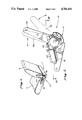
- FIG. 1 is a rear, side perspective view of a vehicle seat having a bottom part and a backrest with an exemplary preferred embodiment of the mechanism of the present invention connecting the two parts of the seat together;
- FIG. 2 is a side view of the mechanism wherein the Section III--III is taken;
- FIG. 3 is a partial sectional view into the top of the mechanism, as revealed by the Section III--III taken in FIG. 2;
- FIG. 4 is a partial sectional view into the opposite side of the mechanism from that depicted in FIG. 2, as revealed by the Section IV--IV taken in FIG. 3;
- FIG. 5 is a partial sectional view looking into the front of the mechanism, as revealed by the Section V--V taken in FIG. 3;
- FIG. 6 is a partial sectional view into the side of the mechanism, as revealed by the Section VI--VI taken in FIG. 5;
- FIG. 7 is a partial sectional view looking into the rear of the mechanism.
- FIG. 8 is a partial sectional view through the side of the mechanism, showing the teeth of the gears in meshing engagement, as revealed by the Section VIII--VIII taken in FIG. 7.
- FIG. 1 An exemplary, preferred embodiment of the apparatus 10 is illustrated generally in FIG. 1 in use in conjunction with a typical automobile seat 1 comprising a bottom or seat part 2 and a bracket part 3 hingeably attached to seat part 2 by means of the apparatus 10.
- the apparatus 10 may be thought to comprise a planetary gear train, including a fixed part 12 containing a first, or fixed, internal gear 14 fixed firmly to seat part 12 and a moving part 20 containing a second, or driven, internal gear 22 supported by fixed part 12 for relative coaxial rotation of gears 14 and 22 attached to backrest part 3.
- a planetary gear train including a fixed part 12 containing a first, or fixed, internal gear 14 fixed firmly to seat part 12 and a moving part 20 containing a second, or driven, internal gear 22 supported by fixed part 12 for relative coaxial rotation of gears 14 and 22 attached to backrest part 3.
- a compound satellite 30 containing a first, or driven, external gear 32 and a second, or driving, external gear 34 is driven eccentrically within the pair of internal gears with planetary motion such that rolling meshing occurs between the respective, mating pairs of gears by means of a cam, or keyed eccentric 40 assembled upon, and driven by, a splined shaft 50 which, in the exemplary preferred embodiment illustrated, may be driven selectively with rotational movement in either direction by means of an electric motor and worm gear assembly 60.
- fixed part 12 comprises an inner part 12A and an outer part 12B which are spaced apart by about the width of moving part 20.
- Each fixed part contains a pair of first internal gears 14A and 14B, respectively, whose tooth forms, or profiles, are stamped or coined into their respective fixed parts.
- Each of the fixed pair of internal gears 14A and 14B contains an integer number N 1 of concave, semicircular teeth 16 about its inner periphery.
- inner fixed part 12A includes an extension in the form of an arm 18 which is attached firmly along the side of bottom part 2 of seat 1 by a plurality of fastener means, such as bolts.
- one, the other, or both of fixed parts 12A and 12B are also formed to include a semicylindrical portion disposed radially thereon to form a semicylindrical, generally radially-inward-facing bearing surface 19 when inner and outer fixed parts 12B and 12A are fastened together by fastener means, such as a plurality of sturdy rivets.
- moving part 20 Clamped between fixed parts 12A and 12B for relative coaxial rotation is moving part 20 which is similarly die-stamped or coined to include the second, or driven, internal gear 22, which comprises an integer number N 4 of concave, semicylindrical internal teeth 24.
- the second, or driven, internal gear 22 is supported for relative coaxial rotation between fixed internal gears 14A and 14B by means of a semicylindrical portion disposed radially on the outer periphery of moving part 20 to form a semicylindrical bearing surface 26 in contact with, and supported by, semicylindrical bearing surface 19.
- Satellite 30 supportsed eccentrically within internal gears 14 and 22 (see FIGS. 5, 6, 7 and 8).
- Satellite 30 includes a pair of annular-shaped external gear profiles 32 and 34 stamped or formed into its external periphery to form a compound gear.
- the first, or driven, external gear 32 contains an integer number N 2 of convex, semi-circular teeth 36 formed radially thereon, which teeth are conjugate with those of internal gear 14 and are less in number by at least 1 than the number N 1 of teeth 16 contained in that gear.
- the second, or driving, external gear 34 on the outer periphery of satellite 30 is die-stamped or coined to include an integer number N 3 of convex, semi-circular teeth 38 which are conjugate with those of internal gear 22 and which are less in number than the number N 4 of teeth 24 on that gear by at least one tooth.
- the pitch radii of external gears 32 and 34 are constrained to be less than that of corresponding, meshing, internal gears 14 and 22, respectively by a constant amount, which amount corresponds to the eccentricity at which satellite 30 is driven within internal gear 14 and at which satellite 30 drives internal gear 22 by means of eccentric 40.
- satellite 30 is shown to be comprised of a pair of substantially identical pairs 30A and 30B of concentric, external gears compounded back-to-back such that the intermediate, or second, external gear 34 is formed in halves 34A and 34B from each of the satellite pair 30A and 30B with a concentric, substantially-identical pair of the first external gears 32A and 32B on either side thereof.
- This form of construction has been shown to achieve a reduction in fabrication costs.
- satellite 30 might easily be formed as a single part, or for that matter, a pair of first external gears 32A and 32B with a single, second external gear 34 compounded coaxially therebetween.
- Satellite 30 is driven eccentrically by means of a cam, or eccentric 40.
- Eccentric 40 is simply an expansion of an arm, or crank, having one end pinioned at the center of the external gears, a second end attached for rotational movement to the center of satellite 30, and a throw, or length, equal to the eccentricity of satellite 30.
- eccentricity becomes extremely small and it becomes desirable to substitute the eccentric 40 illustrated.
- Eccentric 40 has a center concentric with that of satellite 30 and a center of rotation concentric with that of the pair of internal gears 14 and 22.
- eccentric 40 is formed, for ease of machining purposes, from a pair of symmetrical pairs of 40A and 40B splined back-to-back on splined shaft 50.
- Satellite 30 contains a cylindrical opening through it to form an annular bearing surface 39 to receive eccentric 40 for relative sliding rotation.
- Each symmetrical eccentric half 40A and 40B contains a radially-disposed shoulder 42A and 42B, respectively, which, together with bearing surface 39, form an annular-shaped raceway within which friction-reducing means, such as a plurality of ball bearings 44 are disposed for smooth, rolling action.
- Ball bearings 44 are retained in place by means of a pair of axially-spaced keepers 45.
- a splined keyway 46 is formed axially through eccentric 40 to permit it to be assembled in symmetrical halves upon shaft 50 and to be driven rotationally thereby.
- Shaft 50 is rotationally-coupled to gear motor assembly 62 by means of adaptor 52 and gear-motor assembly 62 is mounted to device 10 by means of a spider frame 62.
- first and second internal gears 14 and 22 contain 20 and 25 teeth respectively
- first and second external gears 32 and 34 contain 19 and 24 gears, respectively, which results in a gear train value for apparatus 10 of about -95, i.e., each revolution of eccentric 40 in one direction will result in a rotation of moving part 20 through an arc of about 3.8 degrees in the opposite direction.
- seatback 3 is designed to have a full range of motion of about 30 degrees from a fully-reclined position to a fullyinclined position. This range may be fully traversed in about eight revolutions of shaft 50 in either direction.
- This gear train value also results in a high static load capability and permits the use of apparatus 10 with a wide variety of low-output torque electric motors, such as the electric worm-gear motor 62 illustrated, which is of a type conventionally used to drive electric power windows.
- electric motors such as the electric worm-gear motor 62 illustrated
- Skilled practitioners will recognize that the apparatus lends itself well to other types of motors and transmission means as well, such as a cogged belt used in conjunction with a pair of pulleys, or a flexible shaft arrangement used in combination with a bi-directional electric motor, which may then be located remotely from apparatus 10 to clear surrounding structures.
- the resulting apparatus 10, exclusive of attachment arms 18 and 28 and gear-motor 60 occupies a cylindrical volume of only about 10 centimeters in diameter by about 1.75 centimeters thick.
- This compact size lends apparatus 10 well to single-sided applications in vehicle interiors, such as automobiles, in which it may be incorporated as illustrated on one or the other side of the seat assembly, or it may be compounded in pairs on either side of the seat onto a common driving shaft 50.
- the gear train value of the apparatus 10 may be easily modified one way or the other over a relatively large range by varying the number of teeth, and hence, the pitch radii, of the respective engaging internal and external gear pairs, without adversely affecting the compact size of the device. Accordingly, in budget installations, a manually-adjustable apparatus 10 may be easily achieved by the elimination of the electric motor and transmission means altogether, and their replacement by a simple knob or handle coupled to the outer end of shaft 50.
- the parts are inexpensively stamped from mild steel, which is subsequently heat treated for stength and riveted together before assembly to the seat.
- mild steel which is subsequently heat treated for stength and riveted together.
- other materials, methods of fabrication, and assembly will recommend themselves to skilled practitioners, depending upon the particular application at hand. Accordingly, the scope and spirit of the instant invention should be limited only by the claims appended hereafter.
Landscapes
- Engineering & Computer Science (AREA)
- Aviation & Aerospace Engineering (AREA)
- Transportation (AREA)
- Mechanical Engineering (AREA)
- Chairs For Special Purposes, Such As Reclining Chairs (AREA)
Abstract
Description
Claims (6)
Priority Applications (7)
| Application Number | Priority Date | Filing Date | Title |
|---|---|---|---|
| US06/906,732 US4781416A (en) | 1986-09-11 | 1986-09-11 | Seatback recliner |
| EP87307816A EP0260849A3 (en) | 1986-09-11 | 1987-09-04 | Seatback recliner |
| BR8704660A BR8704660A (en) | 1986-09-11 | 1987-09-08 | MECHANICAL SEAT RECLINATOR WITH ADJUSTABLE SEAT BACKREST |
| KR870009979A KR880003782A (en) | 1986-09-11 | 1987-09-09 | Seatback recliner |
| AU78235/87A AU7823587A (en) | 1986-09-11 | 1987-09-10 | Seatback recliner |
| MX8164A MX161200A (en) | 1986-09-11 | 1987-09-10 | IMPROVEMENTS IN BACKREST RECLINING MECHANISM FOR CAR SEATS |
| JP62228210A JPS6371211A (en) | 1986-09-11 | 1987-09-11 | Seat back recliner |
Applications Claiming Priority (1)
| Application Number | Priority Date | Filing Date | Title |
|---|---|---|---|
| US06/906,732 US4781416A (en) | 1986-09-11 | 1986-09-11 | Seatback recliner |
Publications (1)
| Publication Number | Publication Date |
|---|---|
| US4781416A true US4781416A (en) | 1988-11-01 |
Family
ID=25422891
Family Applications (1)
| Application Number | Title | Priority Date | Filing Date |
|---|---|---|---|
| US06/906,732 Expired - Fee Related US4781416A (en) | 1986-09-11 | 1986-09-11 | Seatback recliner |
Country Status (7)
| Country | Link |
|---|---|
| US (1) | US4781416A (en) |
| EP (1) | EP0260849A3 (en) |
| JP (1) | JPS6371211A (en) |
| KR (1) | KR880003782A (en) |
| AU (1) | AU7823587A (en) |
| BR (1) | BR8704660A (en) |
| MX (1) | MX161200A (en) |
Cited By (22)
| Publication number | Priority date | Publication date | Assignee | Title |
|---|---|---|---|---|
| US4986602A (en) * | 1988-02-23 | 1991-01-22 | Tubauto | Irreversible continuous pivotal connection |
| US4986514A (en) * | 1988-10-31 | 1991-01-22 | Fujikiko Kabushiki Kaisha | Seat reclining device |
| US5277672A (en) * | 1989-06-30 | 1994-01-11 | Ets. Cousin Freres | Clearance take up device for so-called continuous epicycloidal train articulations, and its mounting mode |
| US5282395A (en) * | 1991-11-19 | 1994-02-01 | La-Z-Boy Chair Co. | Recliner handle |
| DE19527483A1 (en) * | 1994-07-29 | 1996-02-01 | Aisin Seiki | Electric drive arrangement for rake adjustment of motor vehicle seat |
| US5542772A (en) * | 1990-11-22 | 1996-08-06 | Alfred Teves Gmbh & Co Ohg | Articulated joint fitting for automotive vehicle seat |
| US5586833A (en) * | 1993-11-30 | 1996-12-24 | Keiper Recaro Gmbh & Co. | Articulated fitting for seats with adjustable backrest, in particular motor vehicle seats |
| US5590491A (en) * | 1994-10-24 | 1997-01-07 | Truth Hardware Corporation | Window operator with dial interface |
| US5895096A (en) * | 1997-04-10 | 1999-04-20 | Lear Corporation | Vehicle seat back assembly and method of making a vehicle seat back assembly |
| WO2000029251A1 (en) * | 1998-11-16 | 2000-05-25 | Dura Global Technologies, Inc. | Recliner control mechanism for a seat assembly |
| US20020167210A1 (en) * | 2001-04-27 | 2002-11-14 | Keiper Gmbh & Co | Geared fitting for a vehicle seat adjuster |
| US20060244296A1 (en) * | 2003-04-07 | 2006-11-02 | Michael Drew | Infinitely variable continuous recliner mechanism for vehicle seats and similar applications |
| DE102006023535A1 (en) * | 2006-05-19 | 2007-11-22 | Keiper Gmbh & Co.Kg | Gear stage for an actuator |
| US20080061616A1 (en) * | 2006-09-12 | 2008-03-13 | Lear Corporation | Continuous recliner |
| US20090051203A1 (en) * | 2005-09-09 | 2009-02-26 | Brose Fahrzeugteile Gmbh & Co. | Adjustment Fitting |
| CN107031462A (en) * | 2015-09-22 | 2017-08-11 | 福特全球技术公司 | Ball bearing application for seat angle adjustor disk mechanism |
| US10195962B2 (en) | 2016-07-14 | 2019-02-05 | Bae Industries, Inc. | Power seat assembly with spring loaded seatback dump and motor driven design rewind and reset functionality |
| US10279712B2 (en) | 2016-07-14 | 2019-05-07 | Bae Industries, Inc. | Rear row seat latch assembly with power and manual driven variants |
| CN111469720A (en) * | 2020-04-22 | 2020-07-31 | 长春富晟汽车零部件有限责任公司 | Electric fast movement device for backrest |
| US10787101B2 (en) * | 2018-06-25 | 2020-09-29 | Faurecia Automotive Seating, Llc | Adjustment mechanism for a vehicle |
| US20220219577A1 (en) * | 2019-05-10 | 2022-07-14 | Adient Us Llc | Fitting for vehicle seat |
| US20220234479A1 (en) * | 2021-01-26 | 2022-07-28 | Jack Q. Xiao | Seat Reclining Mechanism with Protective Cover |
Families Citing this family (2)
| Publication number | Priority date | Publication date | Assignee | Title |
|---|---|---|---|---|
| FR2786446B1 (en) * | 1998-12-01 | 2001-02-16 | Faure Bertrand Equipements Sa | VEHICLE SEAT COMPRISING A ARTICULATION MECHANISM |
| JP2000181461A (en) | 1998-12-10 | 2000-06-30 | Kumamoto Nippon Denki Kk | Sound absorbing device for machine generating mechanical noise |
Citations (10)
| Publication number | Priority date | Publication date | Assignee | Title |
|---|---|---|---|---|
| US3738194A (en) * | 1971-02-11 | 1973-06-12 | Lorence Mfg Corp | Improved speed reducing transmission |
| US3939737A (en) * | 1973-03-16 | 1976-02-24 | Otto Bock Orthopaedische Industrie Kg | Epicyclic transmission with eccentric drive and thrust-transmitting bodies in stationary guide |
| US4196931A (en) * | 1977-07-30 | 1980-04-08 | Keiper Automobiltechnik Gmbh & Co. Kg | Adjustable hinge for a backrest of a vehicle seat |
| US4200333A (en) * | 1977-07-25 | 1980-04-29 | Keiper Automobiltechnik Gmbh & Co. Kg | Adjustable hinge mount for a seatback |
| US4225182A (en) * | 1977-07-30 | 1980-09-30 | Keiper Automobiltechnik Gmbh & Co. Kg | Power driven adjuster for a backrest of a vehicle seat |
| US4302047A (en) * | 1978-11-15 | 1981-11-24 | Keiper Automobiltechnik Gmbh & Co. K.G. | Hinge mount for seats having adjustable backrest |
| US4366983A (en) * | 1980-07-25 | 1983-01-04 | Keiper U.S.A., Inc. | Power recliner |
| US4457556A (en) * | 1976-03-09 | 1984-07-03 | Keiper Automobiltechnik Gmbh & Co. Kg | Fitting for adjustably connecting parts of automotive vehicle seats |
| US4469375A (en) * | 1981-11-25 | 1984-09-04 | Keiper U.S.A., Inc. | Taumel hinge recliner |
| US4505515A (en) * | 1981-07-31 | 1985-03-19 | Keiper Automobiltechnik Gmbh & Co. Kg | Hinge, particularly for seat with adjustable back rest |
Family Cites Families (1)
| Publication number | Priority date | Publication date | Assignee | Title |
|---|---|---|---|---|
| JPS58185947U (en) * | 1982-06-03 | 1983-12-10 | トヨタ自動車株式会社 | Seat reclining device |
-
1986
- 1986-09-11 US US06/906,732 patent/US4781416A/en not_active Expired - Fee Related
-
1987
- 1987-09-04 EP EP87307816A patent/EP0260849A3/en not_active Withdrawn
- 1987-09-08 BR BR8704660A patent/BR8704660A/en unknown
- 1987-09-09 KR KR870009979A patent/KR880003782A/en not_active Ceased
- 1987-09-10 AU AU78235/87A patent/AU7823587A/en not_active Abandoned
- 1987-09-10 MX MX8164A patent/MX161200A/en unknown
- 1987-09-11 JP JP62228210A patent/JPS6371211A/en active Pending
Patent Citations (10)
| Publication number | Priority date | Publication date | Assignee | Title |
|---|---|---|---|---|
| US3738194A (en) * | 1971-02-11 | 1973-06-12 | Lorence Mfg Corp | Improved speed reducing transmission |
| US3939737A (en) * | 1973-03-16 | 1976-02-24 | Otto Bock Orthopaedische Industrie Kg | Epicyclic transmission with eccentric drive and thrust-transmitting bodies in stationary guide |
| US4457556A (en) * | 1976-03-09 | 1984-07-03 | Keiper Automobiltechnik Gmbh & Co. Kg | Fitting for adjustably connecting parts of automotive vehicle seats |
| US4200333A (en) * | 1977-07-25 | 1980-04-29 | Keiper Automobiltechnik Gmbh & Co. Kg | Adjustable hinge mount for a seatback |
| US4196931A (en) * | 1977-07-30 | 1980-04-08 | Keiper Automobiltechnik Gmbh & Co. Kg | Adjustable hinge for a backrest of a vehicle seat |
| US4225182A (en) * | 1977-07-30 | 1980-09-30 | Keiper Automobiltechnik Gmbh & Co. Kg | Power driven adjuster for a backrest of a vehicle seat |
| US4302047A (en) * | 1978-11-15 | 1981-11-24 | Keiper Automobiltechnik Gmbh & Co. K.G. | Hinge mount for seats having adjustable backrest |
| US4366983A (en) * | 1980-07-25 | 1983-01-04 | Keiper U.S.A., Inc. | Power recliner |
| US4505515A (en) * | 1981-07-31 | 1985-03-19 | Keiper Automobiltechnik Gmbh & Co. Kg | Hinge, particularly for seat with adjustable back rest |
| US4469375A (en) * | 1981-11-25 | 1984-09-04 | Keiper U.S.A., Inc. | Taumel hinge recliner |
Cited By (34)
| Publication number | Priority date | Publication date | Assignee | Title |
|---|---|---|---|---|
| US4986602A (en) * | 1988-02-23 | 1991-01-22 | Tubauto | Irreversible continuous pivotal connection |
| US4986514A (en) * | 1988-10-31 | 1991-01-22 | Fujikiko Kabushiki Kaisha | Seat reclining device |
| US5277672A (en) * | 1989-06-30 | 1994-01-11 | Ets. Cousin Freres | Clearance take up device for so-called continuous epicycloidal train articulations, and its mounting mode |
| US5542772A (en) * | 1990-11-22 | 1996-08-06 | Alfred Teves Gmbh & Co Ohg | Articulated joint fitting for automotive vehicle seat |
| US5282395A (en) * | 1991-11-19 | 1994-02-01 | La-Z-Boy Chair Co. | Recliner handle |
| US5586833A (en) * | 1993-11-30 | 1996-12-24 | Keiper Recaro Gmbh & Co. | Articulated fitting for seats with adjustable backrest, in particular motor vehicle seats |
| DE19527483B4 (en) * | 1994-07-29 | 2006-07-06 | Aisin Seiki K.K., Kariya | Motorized recliner of a vehicle seat |
| DE19527483A1 (en) * | 1994-07-29 | 1996-02-01 | Aisin Seiki | Electric drive arrangement for rake adjustment of motor vehicle seat |
| US5590491A (en) * | 1994-10-24 | 1997-01-07 | Truth Hardware Corporation | Window operator with dial interface |
| US5895096A (en) * | 1997-04-10 | 1999-04-20 | Lear Corporation | Vehicle seat back assembly and method of making a vehicle seat back assembly |
| WO2000029251A1 (en) * | 1998-11-16 | 2000-05-25 | Dura Global Technologies, Inc. | Recliner control mechanism for a seat assembly |
| US20020167210A1 (en) * | 2001-04-27 | 2002-11-14 | Keiper Gmbh & Co | Geared fitting for a vehicle seat adjuster |
| US6715832B2 (en) * | 2001-04-27 | 2004-04-06 | Keiper Gmbh & Co. Kg | Geared fitting for a vehicle seat adjuster |
| US20060244296A1 (en) * | 2003-04-07 | 2006-11-02 | Michael Drew | Infinitely variable continuous recliner mechanism for vehicle seats and similar applications |
| US7857391B2 (en) * | 2005-09-09 | 2010-12-28 | Brose Fahzeugteile GmbH & Co. | Adjustment fitting |
| US20090051203A1 (en) * | 2005-09-09 | 2009-02-26 | Brose Fahrzeugteile Gmbh & Co. | Adjustment Fitting |
| DE102006023535B4 (en) * | 2006-05-19 | 2008-12-18 | Keiper Gmbh & Co.Kg | Gear stage for an actuator |
| US20090078066A1 (en) * | 2006-05-19 | 2009-03-26 | Keiper Gmbh & Co. Kg | Gear train for an actuator |
| DE102006023535A1 (en) * | 2006-05-19 | 2007-11-22 | Keiper Gmbh & Co.Kg | Gear stage for an actuator |
| US8298110B2 (en) | 2006-05-19 | 2012-10-30 | Keiper Gmbh & Co. Kg | Gear train for an actuator |
| US20080061616A1 (en) * | 2006-09-12 | 2008-03-13 | Lear Corporation | Continuous recliner |
| US7513573B2 (en) * | 2006-09-12 | 2009-04-07 | Lear Corporation | Continuous recliner |
| CN107031462B (en) * | 2015-09-22 | 2021-03-23 | 福特全球技术公司 | Ball bearing application for disc mechanism of seat angle adjuster |
| US9796301B2 (en) | 2015-09-22 | 2017-10-24 | Ford Global Technologies, Llc | Ball bearing application for seat recliner disk mechanisms |
| US9981570B2 (en) | 2015-09-22 | 2018-05-29 | Ford Global Technologies, Llc | Ball bearing application for seat recliner disk mechanisms |
| CN107031462A (en) * | 2015-09-22 | 2017-08-11 | 福特全球技术公司 | Ball bearing application for seat angle adjustor disk mechanism |
| US10195962B2 (en) | 2016-07-14 | 2019-02-05 | Bae Industries, Inc. | Power seat assembly with spring loaded seatback dump and motor driven design rewind and reset functionality |
| US10279712B2 (en) | 2016-07-14 | 2019-05-07 | Bae Industries, Inc. | Rear row seat latch assembly with power and manual driven variants |
| US10787101B2 (en) * | 2018-06-25 | 2020-09-29 | Faurecia Automotive Seating, Llc | Adjustment mechanism for a vehicle |
| US20220219577A1 (en) * | 2019-05-10 | 2022-07-14 | Adient Us Llc | Fitting for vehicle seat |
| US12115888B2 (en) * | 2019-05-10 | 2024-10-15 | Keiper Seating Mechanisms Co., Ltd | Fitting for vehicle seat |
| CN111469720A (en) * | 2020-04-22 | 2020-07-31 | 长春富晟汽车零部件有限责任公司 | Electric fast movement device for backrest |
| US20220234479A1 (en) * | 2021-01-26 | 2022-07-28 | Jack Q. Xiao | Seat Reclining Mechanism with Protective Cover |
| US11590863B2 (en) * | 2021-01-26 | 2023-02-28 | Creative Cedar Designs, Inc. | Seat reclining mechanism with protective cover |
Also Published As
| Publication number | Publication date |
|---|---|
| JPS6371211A (en) | 1988-03-31 |
| KR880003782A (en) | 1988-05-30 |
| BR8704660A (en) | 1988-04-26 |
| MX161200A (en) | 1990-08-16 |
| EP0260849A2 (en) | 1988-03-23 |
| AU7823587A (en) | 1988-03-17 |
| EP0260849A3 (en) | 1990-05-16 |
Similar Documents
| Publication | Publication Date | Title |
|---|---|---|
| US4781416A (en) | Seatback recliner | |
| US5127286A (en) | Adjustment device for seats | |
| US6283886B1 (en) | Drive for adjustment devices in motor vehicles | |
| US6805650B2 (en) | Planocentric disc recliner | |
| US4884844A (en) | Double stage taumel gear reduction unit | |
| US5005906A (en) | Reclining device | |
| US4225182A (en) | Power driven adjuster for a backrest of a vehicle seat | |
| CA2126224C (en) | Double enveloping worm and gear seat recliner | |
| US4457556A (en) | Fitting for adjustably connecting parts of automotive vehicle seats | |
| JP3071966B2 (en) | Gear reducer for reciprocating rotation | |
| EP1255661A1 (en) | Linear recliner with plastic housing | |
| US6318806B1 (en) | Vehicle seat having a pivot mechanism | |
| FR2418639A1 (en) | JOINT HINGE FOR SEATS WITH ADJUSTABLE BACKREST, IN PARTICULAR MOTOR VEHICLE SEATS | |
| US4200333A (en) | Adjustable hinge mount for a seatback | |
| US4929024A (en) | Power seat recliner | |
| US5913744A (en) | Eccentric gear | |
| FR2629547A1 (en) | GEAR MECHANISM FOR TRANSMITTING A ROTATION MOVEMENT AND MOTOR VEHICLE SEAT ADJUSTMENT MECHANISM | |
| EP0747255B1 (en) | Adjustable seat bearing | |
| GB2218181A (en) | Gearing device | |
| CA2465005A1 (en) | Device for displacing a seat component | |
| US3587350A (en) | Power transmission including friction drive and gear drive | |
| JP4320181B2 (en) | Reducer and reclining device | |
| JPS6387340A (en) | Rear view mirror device for automobile | |
| JP3576256B2 (en) | Power reclining device for seat | |
| CN116442867B (en) | A self-locking rotary mechanism |
Legal Events
| Date | Code | Title | Description |
|---|---|---|---|
| AS | Assignment |
Owner name: SEMEC, INC., 1101 ALLEN DRIVE, TROY, MICHIGAN 4809 Free format text: ASSIGNMENT OF ASSIGNORS INTEREST.;ASSIGNORS:JOHNSON, RICHARD F.;HELD, JAMES D.;SCHULTZ, ELAINE S.;AND OTHERS;REEL/FRAME:004603/0351 Effective date: 19860904 Owner name: SEMEC, INC., A CORP. OF DE., MICHIGAN Free format text: ASSIGNMENT OF ASSIGNORS INTEREST;ASSIGNORS:JOHNSON, RICHARD F.;HELD, JAMES D.;SCHULTZ, ELAINE S.;AND OTHERS;REEL/FRAME:004603/0351 Effective date: 19860904 |
|
| AS | Assignment |
Owner name: MARMON CORPORATION, THE, 39 SOUTH LASALLE STREET, Free format text: ASSIGNMENT OF ASSIGNORS INTEREST.;ASSIGNOR:AMERICAN SAFETY EQUIPMENT CORPORATION;REEL/FRAME:004822/0798 Effective date: 19870922 |
|
| FEPP | Fee payment procedure |
Free format text: PAYOR NUMBER ASSIGNED (ORIGINAL EVENT CODE: ASPN); ENTITY STATUS OF PATENT OWNER: LARGE ENTITY |
|
| AS | Assignment |
Owner name: BERTRAND FAURE AUTOMOBILE, FRANCE Free format text: ASSIGNMENT OF ASSIGNORS INTEREST.;ASSIGNOR:MARMON CORPORATION;REEL/FRAME:005150/0361 Effective date: 19880205 |
|
| FPAY | Fee payment |
Year of fee payment: 4 |
|
| REMI | Maintenance fee reminder mailed | ||
| LAPS | Lapse for failure to pay maintenance fees | ||
| FP | Lapsed due to failure to pay maintenance fee |
Effective date: 19961106 |
|
| STCH | Information on status: patent discontinuation |
Free format text: PATENT EXPIRED DUE TO NONPAYMENT OF MAINTENANCE FEES UNDER 37 CFR 1.362 |