US4778077A - Lid for portable bins - Google Patents
Lid for portable bins Download PDFInfo
- Publication number
- US4778077A US4778077A US07/158,859 US15885988A US4778077A US 4778077 A US4778077 A US 4778077A US 15885988 A US15885988 A US 15885988A US 4778077 A US4778077 A US 4778077A
- Authority
- US
- United States
- Prior art keywords
- passage
- lid member
- lid
- top wall
- rim portion
- Prior art date
- Legal status (The legal status is an assumption and is not a legal conclusion. Google has not performed a legal analysis and makes no representation as to the accuracy of the status listed.)
- Expired - Fee Related
Links
- 239000013590 bulk material Substances 0.000 claims description 4
- 238000009825 accumulation Methods 0.000 claims description 2
- 230000000717 retained effect Effects 0.000 claims description 2
- 238000012423 maintenance Methods 0.000 description 2
- 239000002184 metal Substances 0.000 description 2
- 230000000712 assembly Effects 0.000 description 1
- 238000000429 assembly Methods 0.000 description 1
- 238000010276 construction Methods 0.000 description 1
- 238000006073 displacement reaction Methods 0.000 description 1
- 239000000463 material Substances 0.000 description 1
- 238000012986 modification Methods 0.000 description 1
- 230000004048 modification Effects 0.000 description 1
Images

Classifications
-
- B—PERFORMING OPERATIONS; TRANSPORTING
- B65—CONVEYING; PACKING; STORING; HANDLING THIN OR FILAMENTARY MATERIAL
- B65D—CONTAINERS FOR STORAGE OR TRANSPORT OF ARTICLES OR MATERIALS, e.g. BAGS, BARRELS, BOTTLES, BOXES, CANS, CARTONS, CRATES, DRUMS, JARS, TANKS, HOPPERS, FORWARDING CONTAINERS; ACCESSORIES, CLOSURES, OR FITTINGS THEREFOR; PACKAGING ELEMENTS; PACKAGES
- B65D43/00—Lids or covers for rigid or semi-rigid containers
- B65D43/02—Removable lids or covers
- B65D43/0202—Removable lids or covers without integral tamper element
- B65D43/0225—Removable lids or covers without integral tamper element secured by rotation
- B65D43/0231—Removable lids or covers without integral tamper element secured by rotation only on the outside, or a part turned to the outside, of the mouth of the container
-
- B—PERFORMING OPERATIONS; TRANSPORTING
- B65—CONVEYING; PACKING; STORING; HANDLING THIN OR FILAMENTARY MATERIAL
- B65D—CONTAINERS FOR STORAGE OR TRANSPORT OF ARTICLES OR MATERIALS, e.g. BAGS, BARRELS, BOTTLES, BOXES, CANS, CARTONS, CRATES, DRUMS, JARS, TANKS, HOPPERS, FORWARDING CONTAINERS; ACCESSORIES, CLOSURES, OR FITTINGS THEREFOR; PACKAGING ELEMENTS; PACKAGES
- B65D2543/00—Lids or covers essentially for box-like containers
- B65D2543/00009—Details of lids or covers for rigid or semi-rigid containers
- B65D2543/00018—Overall construction of the lid
- B65D2543/00064—Shape of the outer periphery
- B65D2543/00074—Shape of the outer periphery curved
- B65D2543/00092—Shape of the outer periphery curved circular
-
- B—PERFORMING OPERATIONS; TRANSPORTING
- B65—CONVEYING; PACKING; STORING; HANDLING THIN OR FILAMENTARY MATERIAL
- B65D—CONTAINERS FOR STORAGE OR TRANSPORT OF ARTICLES OR MATERIALS, e.g. BAGS, BARRELS, BOTTLES, BOXES, CANS, CARTONS, CRATES, DRUMS, JARS, TANKS, HOPPERS, FORWARDING CONTAINERS; ACCESSORIES, CLOSURES, OR FITTINGS THEREFOR; PACKAGING ELEMENTS; PACKAGES
- B65D2543/00—Lids or covers essentially for box-like containers
- B65D2543/00009—Details of lids or covers for rigid or semi-rigid containers
- B65D2543/00018—Overall construction of the lid
- B65D2543/00231—Overall construction of the lid made of several pieces
-
- B—PERFORMING OPERATIONS; TRANSPORTING
- B65—CONVEYING; PACKING; STORING; HANDLING THIN OR FILAMENTARY MATERIAL
- B65D—CONTAINERS FOR STORAGE OR TRANSPORT OF ARTICLES OR MATERIALS, e.g. BAGS, BARRELS, BOTTLES, BOXES, CANS, CARTONS, CRATES, DRUMS, JARS, TANKS, HOPPERS, FORWARDING CONTAINERS; ACCESSORIES, CLOSURES, OR FITTINGS THEREFOR; PACKAGING ELEMENTS; PACKAGES
- B65D2543/00—Lids or covers essentially for box-like containers
- B65D2543/00009—Details of lids or covers for rigid or semi-rigid containers
- B65D2543/00018—Overall construction of the lid
- B65D2543/00259—Materials used
- B65D2543/00277—Metal
-
- B—PERFORMING OPERATIONS; TRANSPORTING
- B65—CONVEYING; PACKING; STORING; HANDLING THIN OR FILAMENTARY MATERIAL
- B65D—CONTAINERS FOR STORAGE OR TRANSPORT OF ARTICLES OR MATERIALS, e.g. BAGS, BARRELS, BOTTLES, BOXES, CANS, CARTONS, CRATES, DRUMS, JARS, TANKS, HOPPERS, FORWARDING CONTAINERS; ACCESSORIES, CLOSURES, OR FITTINGS THEREFOR; PACKAGING ELEMENTS; PACKAGES
- B65D2543/00—Lids or covers essentially for box-like containers
- B65D2543/00009—Details of lids or covers for rigid or semi-rigid containers
- B65D2543/00444—Contact between the container and the lid
- B65D2543/00481—Contact between the container and the lid on the inside or the outside of the container
- B65D2543/0049—Contact between the container and the lid on the inside or the outside of the container on the inside, or a part turned to the inside of the mouth of the container
- B65D2543/00518—Skirt
-
- B—PERFORMING OPERATIONS; TRANSPORTING
- B65—CONVEYING; PACKING; STORING; HANDLING THIN OR FILAMENTARY MATERIAL
- B65D—CONTAINERS FOR STORAGE OR TRANSPORT OF ARTICLES OR MATERIALS, e.g. BAGS, BARRELS, BOTTLES, BOXES, CANS, CARTONS, CRATES, DRUMS, JARS, TANKS, HOPPERS, FORWARDING CONTAINERS; ACCESSORIES, CLOSURES, OR FITTINGS THEREFOR; PACKAGING ELEMENTS; PACKAGES
- B65D2543/00—Lids or covers essentially for box-like containers
- B65D2543/00009—Details of lids or covers for rigid or semi-rigid containers
- B65D2543/00444—Contact between the container and the lid
- B65D2543/00481—Contact between the container and the lid on the inside or the outside of the container
- B65D2543/00537—Contact between the container and the lid on the inside or the outside of the container on the outside, or a part turned to the outside of the mouth of the container
-
- B—PERFORMING OPERATIONS; TRANSPORTING
- B65—CONVEYING; PACKING; STORING; HANDLING THIN OR FILAMENTARY MATERIAL
- B65D—CONTAINERS FOR STORAGE OR TRANSPORT OF ARTICLES OR MATERIALS, e.g. BAGS, BARRELS, BOTTLES, BOXES, CANS, CARTONS, CRATES, DRUMS, JARS, TANKS, HOPPERS, FORWARDING CONTAINERS; ACCESSORIES, CLOSURES, OR FITTINGS THEREFOR; PACKAGING ELEMENTS; PACKAGES
- B65D2543/00—Lids or covers essentially for box-like containers
- B65D2543/00009—Details of lids or covers for rigid or semi-rigid containers
- B65D2543/00444—Contact between the container and the lid
- B65D2543/00481—Contact between the container and the lid on the inside or the outside of the container
- B65D2543/00555—Contact between the container and the lid on the inside or the outside of the container on both the inside and the outside
-
- B—PERFORMING OPERATIONS; TRANSPORTING
- B65—CONVEYING; PACKING; STORING; HANDLING THIN OR FILAMENTARY MATERIAL
- B65D—CONTAINERS FOR STORAGE OR TRANSPORT OF ARTICLES OR MATERIALS, e.g. BAGS, BARRELS, BOTTLES, BOXES, CANS, CARTONS, CRATES, DRUMS, JARS, TANKS, HOPPERS, FORWARDING CONTAINERS; ACCESSORIES, CLOSURES, OR FITTINGS THEREFOR; PACKAGING ELEMENTS; PACKAGES
- B65D2543/00—Lids or covers essentially for box-like containers
- B65D2543/00009—Details of lids or covers for rigid or semi-rigid containers
- B65D2543/00444—Contact between the container and the lid
- B65D2543/00574—Contact between the container and the lid secured locally, i.e. a lot less than half the periphery
-
- B—PERFORMING OPERATIONS; TRANSPORTING
- B65—CONVEYING; PACKING; STORING; HANDLING THIN OR FILAMENTARY MATERIAL
- B65D—CONTAINERS FOR STORAGE OR TRANSPORT OF ARTICLES OR MATERIALS, e.g. BAGS, BARRELS, BOTTLES, BOXES, CANS, CARTONS, CRATES, DRUMS, JARS, TANKS, HOPPERS, FORWARDING CONTAINERS; ACCESSORIES, CLOSURES, OR FITTINGS THEREFOR; PACKAGING ELEMENTS; PACKAGES
- B65D2543/00—Lids or covers essentially for box-like containers
- B65D2543/00009—Details of lids or covers for rigid or semi-rigid containers
- B65D2543/00824—Means for facilitating removing of the closure
- B65D2543/00833—Integral tabs, tongues, handles or similar
- B65D2543/00851—Integral tabs, tongues, handles or similar on the central part of the lid
-
- B—PERFORMING OPERATIONS; TRANSPORTING
- B65—CONVEYING; PACKING; STORING; HANDLING THIN OR FILAMENTARY MATERIAL
- B65D—CONTAINERS FOR STORAGE OR TRANSPORT OF ARTICLES OR MATERIALS, e.g. BAGS, BARRELS, BOTTLES, BOXES, CANS, CARTONS, CRATES, DRUMS, JARS, TANKS, HOPPERS, FORWARDING CONTAINERS; ACCESSORIES, CLOSURES, OR FITTINGS THEREFOR; PACKAGING ELEMENTS; PACKAGES
- B65D2543/00—Lids or covers essentially for box-like containers
- B65D2543/00009—Details of lids or covers for rigid or semi-rigid containers
- B65D2543/00953—Sealing means
- B65D2543/00962—Sealing means inserted
- B65D2543/00972—Collars or rings
Definitions
- This invention relates generally to bins and other bulk material containers and more particularly to a closure assembly for a top opening in a bin having improved seal and lid retaining features.
- Closure assemblies are in common use with many tyes of containers and are an essential component in many sealed containers.
- the object of this invention is to provide an improved closure assembly for a portable bulk material handling bin that provides a positive seal and positive retainers to maintain the lid in a sealed configuration in the opening of the bin.
- the closure assembly according to the present invention is designed for application in a bin having a top wall which has a tubular wall portion forming a generally circular passage through the top wall.
- the closure assembly comprises a generally circular lid having a cylindrical rim portion which fits within the passage.
- the rim portion has an outwardly open retaining groove extending circumferentially around the rim portion. Disposed in this groove is an O-ring seal which has a cross-sectional diameter greater than the depth of the groove so that a portion of the O-ring seal projects beyond the edge of the rim.
- an O-ring seal which has a cross-sectional diameter greater than the depth of the groove so that a portion of the O-ring seal projects beyond the edge of the rim.
- the coacting means on the lid and the top wall comprises a lid cowling having a ring shaped base portion fixed symmetrically to the lid and having equally spaced hook shaped retainers projecting outwardly from the base portion and beyond the rim portion of the lid.
- the tubular wall portion of the top wall forming the passage has a like number of outwardly directed tabs which project away from the passage.
- the retainers engage the outwardly directed tabs when the lid is positioned with the rim portion extending downwardly into the passage to close off the passage and the lid is rotated. Rotating the lid engages the retainers with the tabs thereby securing the lid to the bin.
- the closure assembly of the present invention including the O-ring seal disposed groove in the cylindrical portion of the lid has several advantages.
- the interlocking tabs and retainers are simply formed from sheet metal thus simplifying the construction of the closure assembly thereby minimizing cost.
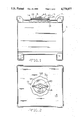
- FIG. 1 is a side view of a portable bin including the closure assembly according to the present invention shown in a partial cut away view;
- FIG. 2 is a top view of the bin having the closure assembly according to the present invention shown in FIG. 1;
- FIG. 3 is a partial top view of the bin shown in FIG. 2 showing the detail of the closure assembly according to the present invention
- FIG. 4 is a partial top view of the closure assembly according to the present invention with the retainers and tabs disengaged;
- FIG. 5 is a partial sectional view along the line 5--5 in FIG. 3;
- FIG. 6 is a sectional view along the line 6--6 shown in FIG. 4.
- Closure assembly 10 includes lid member 18 which has a generally circular portion 20 and a cylindrical rim portion 22 which has an outwardly open retaining groove 24 extending circumferentially around rim portion 22. Disposed in groove 24 is O-ring seal 26, is a ring shaped flexible band having a circular cross-section as shown in FIG. 5. O-ring seal 26 is sized so as to have a portion projecting outwardly from and beyond cylindrical rim 22. Lid member 18 is sized so that the cylindrical end portion 22 has a diameter slightly less than that of passage 12 formed in top wall 14. When O-ring seal 26 is disposed in retaining groove 24, the outer diameter of the lid member including the O-ring seal is slightly greater than the diameter of passage 12.
- Tubular wall portion 28 is formed in top wall 12 and includes outwardly projecting tabs 30. In the embodiment shown, there are eight equally space tabs 30 around the perimeter of passage 12.
- lid cowling 32 Symmetrically attached to central portion 20 of lid member 18 is a lid cowling 32 having a base portion 34 and having a plurality of hook shaped retainers 36 spaced symmetrically around the outer perimeter of the base portion 34 of lid cowling 32 and projecting outwardly beyond rim portion 22 of lid member 18.
- lid cowling 32 has eight hook shaped retainers 36 symmetrically spaced around base section 34 for engagement with the eight tabs 30 as shown in FIGS. 3 and 5.
- the lid cowling 32 is formed from a flat sheet of metal or other generally rigid material. Hook shaped retainers 36 are bent from the sheet to form retainers having a J-shaped cross-section and having ends 38 as shown in FIG. 6. Similarly, tabs 30 on tubular wall portion 28 have corresponding ends 40.
- lid member 18 When lid member 18 is inserted within passage 12 compressing seal 26 to provide a positive seal between cylindrical rim portion 22 of lid member 18 and tubular wall portion 28, lid member 18 may be rotated so as to engage tabs 30 with retainers 36 thereby retaining lid member 18 in place. If needed, holes may be drilled in a tab and opposite retainer for receiving a lock pin or lock wire to prevent inadvertant rotation of the lid member 18 out of engagement between tabs 30 and retainers 36.
- Lid member 18 may have central portion 20 shaped in several configurations. Central portion 20 may be flat or bowed as shown in the embodiment illustrated in FIGS. 1 through 6 and may have a central valley 42 along with a centrally disposed vent cap 44 as shown in FIGS. 1, 2 and 3. Vent cap 44 equalizes the pressure between external atmosphere and the internals of bin 16. Central valley 42 provides a drainage path for moisture that may collect around the base of vent 44.
- O-ring seal 26 is retained within groove 24 by the coaction of opposing shoulders 46 and 48 on cylindrical rim portion 22. Shoulders 46 and 48 prevent displacement of O-ring seal 26 from cylindrical rim portion 22 as lid member 18 is inserted in or withdrawn from passage 12.
- O-ring 26, being flexible, is elastically deformed and uniformly compressed between rim portion 22 and tubular wall portion 28 when the lid member 18 is positioned within passage 12. This provides a positive seal to close passage 12.
- ends 38 and 40 on retainers 36 and tabs 30 respectively secures cylindrical rim portion 22 within passage 12 when lid member 18 is rotated to engage the tabs 30 with retainers 36.
- this invention provides and improved closure device for a portable bin utilizing an O-ring seal on the lid member rather than on the top wall thereby simplifying maintenance, and replacement as well as providing a positive seal of the passage in the top bin.
- the present invention has been described in an illustrative manner and it is to be understood that the terminology which has been used is intended to be in the nature of words of description rather than of limitation. Obviously many modifications and variations of the present invention are possible in light of the above teachings. It is therefore to be understood that within the scope of the appended claims the invention may be practiced otherwise than as specifically described.
Landscapes
- Engineering & Computer Science (AREA)
- Mechanical Engineering (AREA)
- Closures For Containers (AREA)
Abstract
Description
Claims (8)
Priority Applications (1)
| Application Number | Priority Date | Filing Date | Title |
|---|---|---|---|
| US07/158,859 US4778077A (en) | 1988-02-22 | 1988-02-22 | Lid for portable bins |
Applications Claiming Priority (1)
| Application Number | Priority Date | Filing Date | Title |
|---|---|---|---|
| US07/158,859 US4778077A (en) | 1988-02-22 | 1988-02-22 | Lid for portable bins |
Publications (1)
| Publication Number | Publication Date |
|---|---|
| US4778077A true US4778077A (en) | 1988-10-18 |
Family
ID=22570032
Family Applications (1)
| Application Number | Title | Priority Date | Filing Date |
|---|---|---|---|
| US07/158,859 Expired - Fee Related US4778077A (en) | 1988-02-22 | 1988-02-22 | Lid for portable bins |
Country Status (1)
| Country | Link |
|---|---|
| US (1) | US4778077A (en) |
Cited By (1)
| Publication number | Priority date | Publication date | Assignee | Title |
|---|---|---|---|---|
| US20050155982A1 (en) * | 2004-01-20 | 2005-07-21 | David Shannon | Beverage dispenser |
Citations (2)
| Publication number | Priority date | Publication date | Assignee | Title |
|---|---|---|---|---|
| US3433385A (en) * | 1967-09-05 | 1969-03-18 | Joseph Emile Metivier | Bayonet closure for container |
| US3443718A (en) * | 1966-04-25 | 1969-05-13 | Post Willem P | Container closure assembly |
-
1988
- 1988-02-22 US US07/158,859 patent/US4778077A/en not_active Expired - Fee Related
Patent Citations (2)
| Publication number | Priority date | Publication date | Assignee | Title |
|---|---|---|---|---|
| US3443718A (en) * | 1966-04-25 | 1969-05-13 | Post Willem P | Container closure assembly |
| US3433385A (en) * | 1967-09-05 | 1969-03-18 | Joseph Emile Metivier | Bayonet closure for container |
Cited By (2)
| Publication number | Priority date | Publication date | Assignee | Title |
|---|---|---|---|---|
| US20050155982A1 (en) * | 2004-01-20 | 2005-07-21 | David Shannon | Beverage dispenser |
| US7328816B2 (en) * | 2004-01-20 | 2008-02-12 | Carlisle Foodservice Products, Incorporated | Beverage dispenser |
Similar Documents
| Publication | Publication Date | Title |
|---|---|---|
| US3527372A (en) | Container | |
| US4632282A (en) | Spout assembly | |
| US4494674A (en) | Resealable closure and container structure | |
| US5540557A (en) | Vacuum pump for containers | |
| US3499574A (en) | Resilient closure having retaining means | |
| US3840152A (en) | Sealable and resealable container | |
| US6880716B2 (en) | Plastic lid construction | |
| US3623622A (en) | Safety locking closure | |
| US20030010783A1 (en) | Container latch valve | |
| EP0633858B1 (en) | Container and closure | |
| US3589545A (en) | Vented closure | |
| US4116352A (en) | Sealing device | |
| US4881658A (en) | Sealed container | |
| EP0340230A1 (en) | Lidded containers. | |
| US4027777A (en) | Pail assemblies | |
| KR860006242A (en) | Sandwich Cooking & Storage Container Set | |
| US2104540A (en) | Closure for containers | |
| HK1006301B (en) | Container and closure | |
| US20180016063A1 (en) | Durable, child-resistant container with seal thrust bearing | |
| US4665668A (en) | Personal time capsule | |
| US4177933A (en) | Container and closure therefore | |
| US4778077A (en) | Lid for portable bins | |
| US3048297A (en) | Container closure | |
| JP2005193987A (en) | Airtight container for fermented food | |
| US3302822A (en) | Pressure equalizing package |
Legal Events
| Date | Code | Title | Description |
|---|---|---|---|
| AS | Assignment |
Owner name: HOOVER GROUP INC., 1000 HOLCOMB WOODS PARKWAY, SUI Free format text: ASSIGNMENT OF ASSIGNORS INTEREST.;ASSIGNOR:SNYDER, ANDREW W.;REEL/FRAME:004877/0253 Effective date: 19880202 Owner name: HOOVER GROUP INC., A DE CORP., GEORGIA Free format text: ASSIGNMENT OF ASSIGNORS INTEREST;ASSIGNOR:SNYDER, ANDREW W.;REEL/FRAME:004877/0253 Effective date: 19880202 |
|
| FPAY | Fee payment |
Year of fee payment: 4 |
|
| AS | Assignment |
Owner name: NATIONSBANK OF GEORGIA, N.A., AS AGENT, GEORGIA Free format text: CONDITIONAL ASSIGNMENT;ASSIGNOR:HOOVER GROUP, INC.;REEL/FRAME:007046/0409 Effective date: 19940607 |
|
| AS | Assignment |
Owner name: HOOVER MATERIALS HANDLING GROUP, INC., GEORGIA Free format text: ASSIGNMENT OF ASSIGNORS INTEREST;ASSIGNOR:HOOVER GROUP, INC.;REEL/FRAME:007511/0821 Effective date: 19950101 |
|
| AS | Assignment |
Owner name: NATIONSBANK OF GEORGIA, NATIONAL ASSOCIATION, AS A Free format text: ASSIGNMENT OF ASSIGNORS INTEREST;ASSIGNOR:HOOVER MATERIALS HANDLING GROUP, INC.;REEL/FRAME:007596/0877 Effective date: 19950101 |
|
| AS | Assignment |
Owner name: NATIONSBANK OF GEORGIA, NATIONAL ASSOCIATION, AS A Free format text: SECURITY INTEREST;ASSIGNOR:HOOVER MATERIALS HANDLING GROUP, INC.;REEL/FRAME:007696/0839 Effective date: 19950101 |
|
| FPAY | Fee payment |
Year of fee payment: 8 |
|
| AS | Assignment |
Owner name: NATIONSBANK, NATIONAL ASSOCIATION, AS AGENT, NORTH Free format text: CONDITIONAL ASSIGNMENT;ASSIGNOR:HOOVER GROUP, INC.;REEL/FRAME:008999/0721 Effective date: 19980115 |
|
| REMI | Maintenance fee reminder mailed | ||
| LAPS | Lapse for failure to pay maintenance fees | ||
| FP | Lapsed due to failure to pay maintenance fee |
Effective date: 20001018 |
|
| AS | Assignment |
Owner name: GMAC COMMERCIAL CREDIT LLC, NEW YORK Free format text: SECURITY INTEREST;ASSIGNOR:HOOVER GROUP, INC.;REEL/FRAME:011763/0761 Effective date: 20010507 |
|
| AS | Assignment |
Owner name: HOOVER GROUP, INC., GEORGIA Free format text: RELEASE;ASSIGNOR:NATIONSBANK, NATIONAL ASSOCIATION, AS AGENT;REEL/FRAME:011887/0247 Effective date: 20010507 |
|
| AS | Assignment |
Owner name: HOOVER GROUP, INC., GEORGIA Free format text: RELEASE, QUITCLAIM, AND ASSIGNMENT;ASSIGNOR:BANK OF AMERICA, N.A.;REEL/FRAME:015334/0146 Effective date: 20041104 Owner name: HOOVER MATERIALS HANDLING GROUP, INC., GEORGIA Free format text: RELEASE, QUITCLAIM, AND ASSIGNMENT;ASSIGNOR:BANK OF AMERICA, N.A.;REEL/FRAME:015334/0146 Effective date: 20041104 |
|
| STCH | Information on status: patent discontinuation |
Free format text: PATENT EXPIRED DUE TO NONPAYMENT OF MAINTENANCE FEES UNDER 37 CFR 1.362 |