US477780A - Smoke-consuming furnace - Google Patents
Smoke-consuming furnace Download PDFInfo
- Publication number
- US477780A US477780A US477780DA US477780A US 477780 A US477780 A US 477780A US 477780D A US477780D A US 477780DA US 477780 A US477780 A US 477780A
- Authority
- US
- United States
- Prior art keywords
- smoke
- partition
- dampers
- furnace
- boiler
- Prior art date
- Legal status (The legal status is an assumption and is not a legal conclusion. Google has not performed a legal analysis and makes no representation as to the accuracy of the status listed.)
- Expired - Lifetime
Links
- 238000005192 partition Methods 0.000 description 18
- 239000000779 smoke Substances 0.000 description 9
- 239000000446 fuel Substances 0.000 description 6
- 238000002485 combustion reaction Methods 0.000 description 3
- 238000010276 construction Methods 0.000 description 3
- 239000007789 gas Substances 0.000 description 3
- QVGXLLKOCUKJST-UHFFFAOYSA-N atomic oxygen Chemical compound [O] QVGXLLKOCUKJST-UHFFFAOYSA-N 0.000 description 1
- 210000003414 extremity Anatomy 0.000 description 1
- 206010022000 influenza Diseases 0.000 description 1
- 210000003141 lower extremity Anatomy 0.000 description 1
- 239000001301 oxygen Substances 0.000 description 1
- 229910052760 oxygen Inorganic materials 0.000 description 1
- 230000002441 reversible effect Effects 0.000 description 1
- 230000000630 rising effect Effects 0.000 description 1
- 239000007787 solid Substances 0.000 description 1
Images

Classifications
-
- B—PERFORMING OPERATIONS; TRANSPORTING
- B01—PHYSICAL OR CHEMICAL PROCESSES OR APPARATUS IN GENERAL
- B01D—SEPARATION
- B01D53/00—Separation of gases or vapours; Recovering vapours of volatile solvents from gases; Chemical or biological purification of waste gases, e.g. engine exhaust gases, smoke, fumes, flue gases, aerosols
- B01D53/02—Separation of gases or vapours; Recovering vapours of volatile solvents from gases; Chemical or biological purification of waste gases, e.g. engine exhaust gases, smoke, fumes, flue gases, aerosols by adsorption, e.g. preparative gas chromatography
- B01D53/06—Separation of gases or vapours; Recovering vapours of volatile solvents from gases; Chemical or biological purification of waste gases, e.g. engine exhaust gases, smoke, fumes, flue gases, aerosols by adsorption, e.g. preparative gas chromatography with moving adsorbents, e.g. rotating beds
- B01D53/10—Separation of gases or vapours; Recovering vapours of volatile solvents from gases; Chemical or biological purification of waste gases, e.g. engine exhaust gases, smoke, fumes, flue gases, aerosols by adsorption, e.g. preparative gas chromatography with moving adsorbents, e.g. rotating beds with dispersed adsorbents
- B01D53/12—Separation of gases or vapours; Recovering vapours of volatile solvents from gases; Chemical or biological purification of waste gases, e.g. engine exhaust gases, smoke, fumes, flue gases, aerosols by adsorption, e.g. preparative gas chromatography with moving adsorbents, e.g. rotating beds with dispersed adsorbents according to the "fluidised technique"
Definitions
- This invention has for its object to provide a new and improved boiler-furnace of that.
- twin'fireplaces located beneath the boiler are combined with valves, dampers, or gates in such manner that as one fireplace is charged with fresh fuel the smoke and other products of combustion can be caused to pass, beneath the adjacent fireplace, thereby becoming aerated and'j'rising through the in candescent fuel in transit to the chimney or smoke-stack for the purpose of effectually consuming the smoke and gases and eeonomizing' in the consumption of fuel.
- the invention consists, essentially, in the combination, in a steam-boiler furnace, of twin fireplaces open at their tops and provided at theiradjacentsides with vertical walls, a vertical partition extending from the boiler down between the said walls to provide opposite longitudinal fines or passage-ways, a pair of adjustable valves, dampers, or gates arranged, respectively, at or near the lower edge of the partition and below the fireplaces at theadjacent sides thereof, and a pair of adjustable valves, dampers, or gates arranged in flues in the lower portion of the smoke-stack, as will more fully hereinafter appear.
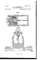
- Figure 1 is a transverse sectional view taken in avertical plane through the twin fireplaces.
- Fig. 2 is a longitudinal sectional view taken on the line or a, Fig. 1.
- Fig. 3 is a horizontal sectional view taken on the line y y, Fig. 1;
- Fig. 4 is a vertical sectional view taken on the line 2 2, Fig. 2.
- the numeral 1 indicates afurnace structure comprising front, rear, and side walls of any materialsuitable for the conditions required and adapted to support a steam-boiler? of any well-known type.
- the forward portion of the furnace structure is provided with twin fireplaces 3, open at their tops for the unobstructed passage of heat to the under side of the boiler.
- the fireplaces comprise grates 4 of any suitable construction, and the adjacent'sides of the fireplaces are provided with'vertical walls 5, separatedfrom each other for the passage between the same of a vertical partition 6, which extends downward from the lower side of the boiler in su'ch'manner as to provide opposite longitudinal fines or passage-ways 7 and 8, formed, respectively, by the lower end portion of the partition and the vertical side walls of the fireplaces.
- the vertical partition extends longitudinally from the front to the rear wall of the furnace structure for the purpose of dividing the latter into two complete sections, and this partition may be solid or it may be hollow for the passage of air to avoid burning or warping.
- a pairof adjustable valves, dampers, or gates 9 and 10 which are, as here shown, adapted to swing in the arcs of circles 011 rock-shafts l2 and 13, having their forward ends extended through the front Wall of the furnace structure and provided with suitable handles 14 and 15 or other device for the purpose by which to turn the shafts for adjusting the valves, dampers, or gates.
- a longitudinal di- Vision-Wall16 divides the base of the furnace structure into a pair of ash-pits 17 and 18, and this division-wall is located directly beneath the partition 6 and fiues or passages 7 and 8, so that the free edges of the valves or dampers or gates 9 and 10 can be brought to rest against the upper end portion of the partition-wall.
- a smoke-stack 19 is arranged at one end of the furnace structure and its lower portionor swell contains a vertical partition 20, which constitutes a continuation of the longitudinal partition 6 for the purpose of dividing the lower portion of the smoke-stack into two corresponding lines 20 and 21.
- the pair of valves, dampers, or gates 22 and 23 are arranged, respectively, in the lines 20 and 21, and at their outer ends are provided with suitable handles 24 and 25 or other devices by which to adjust them into the position required.
- the lower extremities of the divergent walls 26 and 27 are joined to the partition 20 by converging walls 30and 31, thereby providing the upper nace, of twin fireplaces open at their tops and I provided at their adjacent sides with vertical walls, a vertical partition extending from the boiler down between the said vertical walls to end portion of the partition 20 with a wedgeshaped enlargement for the purpose of providing the proper spaces to receive the valves, dampers, or gates, and also affording supports for the shafts which carry such valves, dampers, or gates.
- the damper or gate 9 be vertical, the damper 22 closed, the damper 1O horizontal, and the damper 23 open the reverse action will occur.
- My invention provides a simple, economical, and efficient construction which fulfills all the conditions required to consume the smoke in a steam-boiler furnace.
Landscapes
- Chemical & Material Sciences (AREA)
- Dispersion Chemistry (AREA)
- Engineering & Computer Science (AREA)
- Analytical Chemistry (AREA)
- General Chemical & Material Sciences (AREA)
- Oil, Petroleum & Natural Gas (AREA)
- Chemical Kinetics & Catalysis (AREA)
Description
2 Sheets-Sheet 1.
(No Model.)
G. S. RILEY. SMOKE.GONSUMING FURNACE.-
ggtented'June 28, 1892.
I ye/d 1%? Whammy.
(No Model.) 2 Sheets-Sheet 2.
7 G. S. RILEY.
SMOKE UONSUMING FURNACE.
No. 477,780. Patented June 28, 1892.
UNrTED TATES V-ATENT OFFICIEQY' GEORGE S. RILEY, OF ROCHESTER, NEW YORK.
SMOKE-CONSUMING FURNACE.
SPECIFICATION forming part of Letters Patent 1\l'o. 477,780, dated J une 28, 1892.
4 Application filed October 8, 1891- Scrial No. 408,189. (No model.)
To all whofiz it may concern.-
Be it known that I, GEORGE S. RILEY, a citizen of the United States, residing'at Rochester,in the countyof Monroe and State of New York,have invented new and useful Improvements. in, Smoke- Consuming Furnaces, of which the following is a specification.
This inventionhas for its object to provide a new and improved boiler-furnace of that.
type wherein twin'fireplaces located beneath the boiler are combined with valves, dampers, or gates in such manner that as one fireplace is charged with fresh fuel the smoke and other products of combustion can be caused to pass, beneath the adjacent fireplace, thereby becoming aerated and'j'rising through the in candescent fuel in transit to the chimney or smoke-stack for the purpose of effectually consuming the smoke and gases and eeonomizing' in the consumption of fuel.
The invention consists, essentially, in the combination, in a steam-boiler furnace, of twin fireplaces open at their tops and provided at theiradjacentsides with vertical walls, a vertical partition extending from the boiler down between the said walls to provide opposite longitudinal fines or passage-ways, a pair of adjustable valves, dampers, or gates arranged, respectively, at or near the lower edge of the partition and below the fireplaces at theadjacent sides thereof, and a pair of adjustable valves, dampers, or gates arranged in flues in the lower portion of the smoke-stack, as will more fully hereinafter appear.
The invention also consists in other features of construction and combination or arrangement of parts hereinafter described and claimed, reference being made to the accompanying drawings, in which Figure 1 is a transverse sectional view taken in avertical plane through the twin fireplaces. Fig. 2 is a longitudinal sectional view taken on the line or a, Fig. 1. Fig. 3 is a horizontal sectional view taken on the line y y, Fig. 1;
and Fig. 4 is a vertical sectional view taken on the line 2 2, Fig. 2.
In order to enable those skilled in the art to make and use my invention, I will now describe the same in detail, referring to the drawings, wherein- The numeral 1 indicates afurnace structure comprising front, rear, and side walls of any materialsuitable for the conditions required and adapted to support a steam-boiler? of any well-known type. The forward portion of the furnace structure is provided with twin fireplaces 3, open at their tops for the unobstructed passage of heat to the under side of the boiler. The fireplaces comprise grates 4 of any suitable construction, and the adjacent'sides of the fireplaces are provided with'vertical walls 5, separatedfrom each other for the passage between the same of a vertical partition 6, which extends downward from the lower side of the boiler in su'ch'manner as to provide opposite longitudinal fines or passage-ways 7 and 8, formed, respectively, by the lower end portion of the partition and the vertical side walls of the fireplaces. The vertical partition extends longitudinally from the front to the rear wall of the furnace structure for the purpose of dividing the latter into two complete sections, and this partition may be solid or it may be hollow for the passage of air to avoid burning or warping. At or near the lower edge of the partition and beneath the fireplaces at the adjacent sides thereof is arranged a pairof adjustable valves, dampers, or gates 9 and 10, which are, as here shown, adapted to swing in the arcs of circles 011 rock-shafts l2 and 13, having their forward ends extended through the front Wall of the furnace structure and provided with suitable handles 14 and 15 or other device for the purpose by which to turn the shafts for adjusting the valves, dampers, or gates. A longitudinal di- Vision-Wall16 divides the base of the furnace structure into a pair of ash- pits 17 and 18, and this division-wall is located directly beneath the partition 6 and fiues or passages 7 and 8, so that the free edges of the valves or dampers or gates 9 and 10 can be brought to rest against the upper end portion of the partition-wall.
A smoke-stack 19 is arranged at one end of the furnace structure and its lower portionor swell contains a vertical partition 20, which constitutes a continuation of the longitudinal partition 6 for the purpose of dividing the lower portion of the smoke-stack into two corresponding lines 20 and 21. The pair of valves, dampers, or gates 22 and 23 are arranged, respectively, in the lines 20 and 21, and at their outer ends are provided with suitable handles 24 and 25 or other devices by which to adjust them into the position required. The s1noke-stackis tapering at its base portion, and in order to provide the proper square or other properly-shaped orifices for the arrangement of the valves, dampers,-or gates 22 and 23 I construct the upper portion of the partition 20 with divergent walls 26 and 27, in which are journaled the inner extremities of the shafts 28 and 29 of the valves, dampers, or gates 22 and 23, which may be square, circular, or other convenient shape. The lower extremities of the divergent walls 26 and 27 are joined to the partition 20 by converging walls 30and 31, thereby providing the upper nace, of twin fireplaces open at their tops and I provided at their adjacent sides with vertical walls, a vertical partition extending from the boiler down between the said vertical walls to end portion of the partition 20 with a wedgeshaped enlargement for the purpose of providing the proper spaces to receive the valves, dampers, or gates, and also affording supports for the shafts which carry such valves, dampers, or gates.
In the drawingsl have exhibited the smoke stack as located at the rear of the furnace structure; but if the boiler is provided with return-fines in the usual manner the smokestack will accordingly be located at the front of the furnace structure in a manner which will be obvious to those skilled in the art, for which reason I do not deem it essential to illustrate this arrangement in the drawings.
In the practical operation of the furnace, if the damper or gate 10 is adjusted to a vertical position and rests against the partition wall 16, and the valve, damper, or gate 23 in the smoke-stack is closed, while the damper 9 is horizontal and the damper 22 is open, the smoke and other products of combustion from the fireplace 3 will descend through the flue or passage-way 8 to a point beneath the adjacent fireplace and becoming aerated rise through the incandescent fuel therein, by 1 my hand and affixed my seal in presence of two subscribing witnesses.
which means the smoke and gases from the freshly-charged fireplace are effectually consumed by passing through the incandescent 5 Obviously if 1 flue in the adjacent fireplace.
the damper or gate 9 be vertical, the damper 22 closed, the damper 1O horizontal, and the damper 23 open the reverse action will occur. By this means as one fireplace is charged with fresh fuel the smoke and other products of combustion therefrom can be caused to pass beneath the adjacent fireplace, there becomin g charged with oxygen, and rise through the incandescent fuel in transit to the chimney or smoke-stack for the purpose of effectually consuming the smoke and gases.
My invention provides a simple, economical, and efficient construction which fulfills all the conditions required to consume the smoke in a steam-boiler furnace.
Having thus described my invention, what I claim is- 1. The combination, in a steam-boiler furprovide opposite longitudinal fines or passageways 7 and 8, and a pair of adjustable valves,
l dampers, or gates arranged, respectively, be-
low the twin fireplaces at the adjacent sides thereof, substantially as described.
2. The combination, in a steam-boiler furnace, of twin fireplaces open at their tops and provided at their adjacent sides with vertical walls, a vertical partition extending from the boiler down between the said vertical walls to provide opposite longitudinal fines or passageways, 7 and 8, a pair of adjustable valves, dampers, or gates arranged, respectively, be-
a low the fireplaces at the adjacent sides thereof, a smoke-stack containing a partition which 1; forms a continuation of the partition beneath 3 the boiler for dividing a portion of the smokestack into two fines, and a pair of adjustable valves, dampers, or gates arranged, respect- Iively, in the said fines, substantially as described.
In testimony whereof I have hereunto set GEO. S. RILEY. [L. s]
Vitnesses:
WM. C. LOWREY, WVM. H. FARRAND.
Publications (1)
| Publication Number | Publication Date |
|---|---|
| US477780A true US477780A (en) | 1892-06-28 |
Family
ID=2546635
Family Applications (1)
| Application Number | Title | Priority Date | Filing Date |
|---|---|---|---|
| US477780D Expired - Lifetime US477780A (en) | Smoke-consuming furnace |
Country Status (1)
| Country | Link |
|---|---|
| US (1) | US477780A (en) |
Cited By (1)
| Publication number | Priority date | Publication date | Assignee | Title |
|---|---|---|---|---|
| US20110144510A1 (en) * | 2009-12-16 | 2011-06-16 | Pacesetter, Inc. | Methods to identify damaged or scarred tissue based on position information and physiological information |
-
0
- US US477780D patent/US477780A/en not_active Expired - Lifetime
Cited By (1)
| Publication number | Priority date | Publication date | Assignee | Title |
|---|---|---|---|---|
| US20110144510A1 (en) * | 2009-12-16 | 2011-06-16 | Pacesetter, Inc. | Methods to identify damaged or scarred tissue based on position information and physiological information |
Similar Documents
| Publication | Publication Date | Title |
|---|---|---|
| US498182A (en) | Smoke-consuming furnace | |
| US263498A (en) | Stove | |
| US636044A (en) | Smoke-consuming flue. | |
| US650821A (en) | Furnace. | |
| US627688A (en) | Device for introducing air into steam-boiler furnaces. | |
| US680107A (en) | Furnace. | |
| US750759A (en) | Furnace | |
| US517238A (en) | Smoke consumer | |
| US731546A (en) | Smoke-consuming furnace. | |
| US433837A (en) | Steam-boiler furnace | |
| US341008A (en) | Furnace | |
| US707495A (en) | Steam-boiler furnace. | |
| US1072578A (en) | Gas-furnace. | |
| US910032A (en) | Smoke-consuming furnace. | |
| US667064A (en) | Stove. | |
| US819183A (en) | Furnace. | |
| US747020A (en) | Furnace. | |
| US667750A (en) | Apparatus for consuming smoke in furnaces. | |
| US630703A (en) | Smoke-consumer. | |
| US322994A (en) | Regenerative natural-gas furnace | |
| US371334A (en) | Regenerating-furnace | |
| US352217A (en) | Loco motive-furnace | |
| US674992A (en) | Furnace. | |
| US750860A (en) | Smoke-consumer | |
| US573385A (en) | Smoke consuming furnace |