US4773799A - Apparatus for sampling a section of tube in a nuclear fuel assembly - Google Patents
Apparatus for sampling a section of tube in a nuclear fuel assembly Download PDFInfo
- Publication number
- US4773799A US4773799A US07/056,933 US5693387A US4773799A US 4773799 A US4773799 A US 4773799A US 5693387 A US5693387 A US 5693387A US 4773799 A US4773799 A US 4773799A
- Authority
- US
- United States
- Prior art keywords
- tube
- sleeve
- spindle
- rotation
- fuel assembly
- Prior art date
- Legal status (The legal status is an assumption and is not a legal conclusion. Google has not performed a legal analysis and makes no representation as to the accuracy of the status listed.)
- Expired - Lifetime
Links
Images


Classifications
-
- G—PHYSICS
- G21—NUCLEAR PHYSICS; NUCLEAR ENGINEERING
- G21C—NUCLEAR REACTORS
- G21C17/00—Monitoring; Testing ; Maintaining
-
- G—PHYSICS
- G01—MEASURING; TESTING
- G01N—INVESTIGATING OR ANALYSING MATERIALS BY DETERMINING THEIR CHEMICAL OR PHYSICAL PROPERTIES
- G01N1/00—Sampling; Preparing specimens for investigation
- G01N1/02—Devices for withdrawing samples
- G01N1/04—Devices for withdrawing samples in the solid state, e.g. by cutting
-
- G—PHYSICS
- G21—NUCLEAR PHYSICS; NUCLEAR ENGINEERING
- G21C—NUCLEAR REACTORS
- G21C17/00—Monitoring; Testing ; Maintaining
- G21C17/06—Devices or arrangements for monitoring or testing fuel or fuel elements outside the reactor core, e.g. for burn-up, for contamination
-
- Y—GENERAL TAGGING OF NEW TECHNOLOGICAL DEVELOPMENTS; GENERAL TAGGING OF CROSS-SECTIONAL TECHNOLOGIES SPANNING OVER SEVERAL SECTIONS OF THE IPC; TECHNICAL SUBJECTS COVERED BY FORMER USPC CROSS-REFERENCE ART COLLECTIONS [XRACs] AND DIGESTS
- Y02—TECHNOLOGIES OR APPLICATIONS FOR MITIGATION OR ADAPTATION AGAINST CLIMATE CHANGE
- Y02E—REDUCTION OF GREENHOUSE GAS [GHG] EMISSIONS, RELATED TO ENERGY GENERATION, TRANSMISSION OR DISTRIBUTION
- Y02E30/00—Energy generation of nuclear origin
- Y02E30/30—Nuclear fission reactors
-
- Y—GENERAL TAGGING OF NEW TECHNOLOGICAL DEVELOPMENTS; GENERAL TAGGING OF CROSS-SECTIONAL TECHNOLOGIES SPANNING OVER SEVERAL SECTIONS OF THE IPC; TECHNICAL SUBJECTS COVERED BY FORMER USPC CROSS-REFERENCE ART COLLECTIONS [XRACs] AND DIGESTS
- Y10—TECHNICAL SUBJECTS COVERED BY FORMER USPC
- Y10T—TECHNICAL SUBJECTS COVERED BY FORMER US CLASSIFICATION
- Y10T29/00—Metal working
- Y10T29/53—Means to assemble or disassemble
- Y10T29/531—Nuclear device
-
- Y—GENERAL TAGGING OF NEW TECHNOLOGICAL DEVELOPMENTS; GENERAL TAGGING OF CROSS-SECTIONAL TECHNOLOGIES SPANNING OVER SEVERAL SECTIONS OF THE IPC; TECHNICAL SUBJECTS COVERED BY FORMER USPC CROSS-REFERENCE ART COLLECTIONS [XRACs] AND DIGESTS
- Y10—TECHNICAL SUBJECTS COVERED BY FORMER USPC
- Y10T—TECHNICAL SUBJECTS COVERED BY FORMER US CLASSIFICATION
- Y10T408/00—Cutting by use of rotating axially moving tool
- Y10T408/83—Tool-support with means to move Tool relative to tool-support
- Y10T408/85—Tool-support with means to move Tool relative to tool-support to move radially
- Y10T408/854—Tool-support with means to move Tool relative to tool-support to move radially to move eccentrically mounted Tool
-
- Y—GENERAL TAGGING OF NEW TECHNOLOGICAL DEVELOPMENTS; GENERAL TAGGING OF CROSS-SECTIONAL TECHNOLOGIES SPANNING OVER SEVERAL SECTIONS OF THE IPC; TECHNICAL SUBJECTS COVERED BY FORMER USPC CROSS-REFERENCE ART COLLECTIONS [XRACs] AND DIGESTS
- Y10—TECHNICAL SUBJECTS COVERED BY FORMER USPC
- Y10T—TECHNICAL SUBJECTS COVERED BY FORMER US CLASSIFICATION
- Y10T408/00—Cutting by use of rotating axially moving tool
- Y10T408/83—Tool-support with means to move Tool relative to tool-support
- Y10T408/85—Tool-support with means to move Tool relative to tool-support to move radially
- Y10T408/858—Moving means including wedge, screw or cam
- Y10T408/8588—Axially slidable moving-means
- Y10T408/85892—Screw driven wedge or cam
-
- Y—GENERAL TAGGING OF NEW TECHNOLOGICAL DEVELOPMENTS; GENERAL TAGGING OF CROSS-SECTIONAL TECHNOLOGIES SPANNING OVER SEVERAL SECTIONS OF THE IPC; TECHNICAL SUBJECTS COVERED BY FORMER USPC CROSS-REFERENCE ART COLLECTIONS [XRACs] AND DIGESTS
- Y10—TECHNICAL SUBJECTS COVERED BY FORMER USPC
- Y10T—TECHNICAL SUBJECTS COVERED BY FORMER US CLASSIFICATION
- Y10T409/00—Gear cutting, milling, or planing
- Y10T409/30—Milling
- Y10T409/306664—Milling including means to infeed rotary cutter toward work
- Y10T409/30756—Machining arcuate surface
- Y10T409/307616—Machining arcuate surface with means to move cutter eccentrically
-
- Y—GENERAL TAGGING OF NEW TECHNOLOGICAL DEVELOPMENTS; GENERAL TAGGING OF CROSS-SECTIONAL TECHNOLOGIES SPANNING OVER SEVERAL SECTIONS OF THE IPC; TECHNICAL SUBJECTS COVERED BY FORMER USPC CROSS-REFERENCE ART COLLECTIONS [XRACs] AND DIGESTS
- Y10—TECHNICAL SUBJECTS COVERED BY FORMER USPC
- Y10T—TECHNICAL SUBJECTS COVERED BY FORMER US CLASSIFICATION
- Y10T82/00—Turning
- Y10T82/16—Severing or cut-off
- Y10T82/16426—Infeed means
- Y10T82/16639—Tool within work
-
- Y—GENERAL TAGGING OF NEW TECHNOLOGICAL DEVELOPMENTS; GENERAL TAGGING OF CROSS-SECTIONAL TECHNOLOGIES SPANNING OVER SEVERAL SECTIONS OF THE IPC; TECHNICAL SUBJECTS COVERED BY FORMER USPC CROSS-REFERENCE ART COLLECTIONS [XRACs] AND DIGESTS
- Y10—TECHNICAL SUBJECTS COVERED BY FORMER USPC
- Y10T—TECHNICAL SUBJECTS COVERED BY FORMER US CLASSIFICATION
- Y10T82/00—Turning
- Y10T82/22—Portable lathe for pipe turning
Definitions
- the invention relates to an apparatus for sampling a section of tube in a nuclear fuel assembly of the type comprising a skeleton having two end-pieces and a plurality of grids distributed between the end-pieces along the tubes and arranged to retain a bundle of fuel elements between the end-pieces.
- Most fuel assemblies of the above type used at the present time comprise tubes which constitute guides for rods of a control cluster.
- Each tube is fixed to the lower end-piece by a screw and to the upper end-piece by a sleeve crimped in the end-piece and projecting through the upper grid. It is often desirable to sample a section of the connecting structure between the tube and the upper end-piece to perform a corrosion examination on the sample providing an indication on the condition of the assembly skeleton.
- a cutting tool is used which may be of various types inserted within the tube for sectioning it from inside.
- the tool may be as described in French No. 2,416,760. Processes and apparatus for completely dismantling fuel assembllies are also known (French No. 2,499,296).
- a method including the steps of: cutting out an opening for extraction of the section through the upper end-piece with a milling cutter; sectioning the tube from the inside under the junction thereof with the upper end-piece with a rotary tool inserted through the upper end-piece; and extracting a sample of the latter through the opening.
- the method is particularly applicable to fuel assemblies whose tubes are fixed to a sleeve welded to the upper end-piece. Then it is possible to cut the assembly consisting of the tube and its fastening sleeve between the upper end-piece and the highest grid.
- FIG. 1 is a diagrammatic view in elevation and in partial cross-section of the upper part of a fuel assembly to which the method according to the invention may be applied;
- FIG. 2 shows diagrammatically, in elevation and in partial section, how an opening for extraction of a tube section is cut out in the adaptor plate of the upper end-piece shown in FIG. 1;
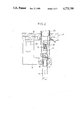
- FIG. 3 shows a tool for cutting a section of tube and of sleeve for obtaining a sample
- FIG. 4 is a section along line IV--IV of FIG. 3.
- a fuel assembly comprises a bundle of fuel elements 11 retained by grids 12 distributed along the bundle.
- the grids 12 define passages the majority of which are traversed by fuel elements 11.
- the other passages receive tubes 15.
- Each tube 15 is fixed to the lower end-piece (not shown) by connecting means, generally constituted by a screw to be dismountable.
- Each tube 15 is fixed to the upper end-piece 14 through a sleeve 16.
- sleeve 16 is welded to the adaptor part of the end-piece 14.
- other connections are possible, for instance by radial expansion into a counterbore of the adaptor parts.
- the sleeve passes through the upper grid 12, to which it may be fixed, and terminates immediately under the grid.
- the tube 15 is fixed to the sleeve 16 by crimpings 19 at intermediate locations. As shown in FIG. 2, crimping is in the form of a plurality of local expansions. Additionally, the upper end of tube 15 may be crimped in the sleeve.
- the tubes 15 are typically of zirconium-based alloy, whilst the sleeves are typically of stainless steel.
- Cutting off and removal of a longitudinal section of the assembly of a tube 15 and its connection to the upper end-piece 14 involve, first, cutting out a passage opening in the upper end-piece 14, second, sectioning the assembly constituted by the tube 15 and the sleeve 16 for separating it from the balance of the tube.
- FIG. 2 shows the lower part of the cutting tool 20, mounted on a mask 22 which guides the tool.
- the mask comprises a base plate 24 provided with pins 26 insertable in indexing and centering blind holes formed in the end-piece 14.
- the tool 20 comprises a sleeve 28 provided with retainer pins 30 for locking it in the base plate 24 of the mask 22 and a unit rotatably mounted in the sleeve 28 and connected to the shaft of a motor (not shown).
- the lower element of the rotary unit consists of a tubular spindle 32 internally threaded for receiving a bladed milling cutter 34, such as a hand wheel, or provided for moving the rotary mechanism downwards and upwards with respect to the sleeve 28.
- the milling tool may be formed with a suction passage (not shown) for drawing the chips and dust which collect in the annular space between the sleeve 28 and the spindle 32.
- the opening for passage of the section to be extracted is cut out conventionally: the spindle 32 carrying the cutter 34 is rotated and progressively lowered until it has passed fully through the plate of end part 14.
- the outer diameter of the cutter must be large enough to permit removal of the section. If the connection between the tube and sleeve include projecting zones, as illustrated in FIG. 2, the opening formed by the cutter must have a sufficient diameter to permit these zones to pass.
- the tube 15 and sleeve 16 may be cut off with the milling tool of FIG. 2, after the cutter 34 has been replaced with an assembly as shown in FIGS. 3 and 4.
- This assembly comprises a fixed structure comprising a fastening ring 36 which is connected, for example by screws (not shown), to the nose 38 of the stationary part of the tool.
- the structure also comprises tie rods 40, for example four in number, which connect the ring 36 to a supporting sole plate 42.
- the sole 42 has a downwardly extending tubular projection which constitutes a guide tube 44 and carries a ball bearing 46 coaxial with the spindle for receiving the rotary unit of the tool.
- the rotary unit of the tool comprises a casing 52 rotating freely in the bearing 46 and having a key 54 engaging into an axial groove of a drive tube 56 for mutual sliding connection.
- An upper end piece is securely connected to tube 56, for instance by screws and has a threaded portion for connection with the spindle 32 in substitution for the cutter 34 of FIG. 2.
- An upper end portion of casing 52 is tubular and defines a chamber receiving a bulged portion of a shank or shaft 60.
- a bearing 65 carried by the sleeve 52 supports the shank for mutual rotation about an axis 50 radially offset with respect to the axis 48 of the spindle 32, for a purpose which will be apparent below.
- An end shoulder of the bulged portion is maintained in abutting contact with the bearing 65 by a ring 59 fixed to casing 52 by a radial pin 58.
- the lower end portion of shank 60 projects out of the casing 52 and a cutter element 62 is secured thereto by a nut 64.
- the rotary unit of the tool further comprises an adjustment shaft 65 whose axial displacement controls the angular portion of the cutter element 62 and consequently its amount of radial projection with respect to axis 48, since it rotates about the offset axis 50.
- a helical connection is provided between shaft 66 and shank 60. As shown in FIG. 3, it comprises helical grooves formed in shaft 66 and splines or fingers 67 of the bulged portion protruding into the grooves.
- the distance from the end fitting at which the spacer tube 15 and the sleeve 16 will be cut off is determined by the length of the spindle 60 from the support represented by the sole 42.
- the sole is supported by a respective mask (not shown) which may be similar to those described in the above-mentioned patents.
- the sequence of operations for cutting a sample is as follows.
- the nose of the tool is located on the fastening ring 36 of the stationary structure and the upper end piece of the drive tube 56 is fixed to spindle 32, while the spindle is in its uppermost portion.
- shaft 66 retains the cutter element 62 in retracted condition, as shown in dash-dot lines in FIG. 4.
- a return spring 70 may be provided for biasing the shaft and spindle upwardly.
- the motor of the tool is energized for driving the rotary unit and the rotary spindle of the tool is progressively lowered. Downward movement of the spindle 32 and shaft 66 causes the shank 60 to rotate about its axis due to the helical coupling between shaft 66 and the shank 60. Rotation of the shank 60 moves the cutting element 62 towards the position in which it is shown in solid lines in FIG. 4.
- the amount of angular travel ⁇ , and hence the maximum radial projection of the cutter element 62, may be adjusted with an abutment ring 68 threadedly received on drive tube 56. Downward movement of the unit consisting of spindle 32, shaft 66, drive tube 56 and ring 68 is limited by abutment of ring 68 onto a radial flange of casing 52, as shown in FIG. 3. Preliminary adjustment of the final position of the cutting element eliminates the risk of damaging an adjacent fuel element.
- tube 15 and sleeve 16 are retained against rotation by the usual fastening of the sleeve 16 to the upper grid 12 and possibly the connections of tube 15 with other grids and the lower end-piece (not shown).
- the cut-off section can then be removed, possibly along with the tool since it is supported by the cutter element 62 held in its position of maximum projection, and then introduced into a closable handling and protection container. Then the container may be transported to a laboratory for analysis.
- the fuel assembly can again be handled, for example for transfer to a deactivation pool or for containment in a container, with an apparatus which may be as described in European No. 138 711 already mentioned.
Abstract
Description
Claims (3)
Applications Claiming Priority (2)
| Application Number | Priority Date | Filing Date | Title |
|---|---|---|---|
| FR8607973A FR2599541B1 (en) | 1986-06-03 | 1986-06-03 | METHOD AND INSTALLATION FOR TAKING THE TUBE SECTION FROM A NUCLEAR FUEL ASSEMBLY |
| FR8607973 | 1986-06-03 |
Publications (1)
| Publication Number | Publication Date |
|---|---|
| US4773799A true US4773799A (en) | 1988-09-27 |
Family
ID=9335944
Family Applications (1)
| Application Number | Title | Priority Date | Filing Date |
|---|---|---|---|
| US07/056,933 Expired - Lifetime US4773799A (en) | 1986-06-03 | 1987-06-03 | Apparatus for sampling a section of tube in a nuclear fuel assembly |
Country Status (2)
| Country | Link |
|---|---|
| US (1) | US4773799A (en) |
| FR (1) | FR2599541B1 (en) |
Cited By (12)
| Publication number | Priority date | Publication date | Assignee | Title |
|---|---|---|---|---|
| US5030042A (en) * | 1989-07-04 | 1991-07-09 | Fuji Seiko Limited | Machining apparatus having means for changing radial position of cutting tools |
| US5061125A (en) * | 1989-08-23 | 1991-10-29 | Cross Europa-Werk, Gmbh | Boring device |
| US5569393A (en) * | 1994-07-08 | 1996-10-29 | Reinhart & Associates, Inc. | Method and apparatus for sample and defect removal from a bore |
| US5675096A (en) * | 1994-12-14 | 1997-10-07 | Westinghouse Electric Corporation | Apparatus and method for removing a wall portion from a wall of a tubular member |
| US6406064B1 (en) * | 1999-11-03 | 2002-06-18 | Westinghouse Electric Company Llc | Positive locking device for reactor instrumentation protection sleeve assembly |
| US20060070465A1 (en) * | 2004-10-04 | 2006-04-06 | Monika Trapp | Sample machining device and sample analysis device |
| US20090193932A1 (en) * | 2005-09-02 | 2009-08-06 | Mapal Fabrik Fur Prazisionswerkzeuge Dr. Kress Kg | Tool for Machining Workpiece Surfaces |
| US20100012627A1 (en) * | 2006-03-14 | 2010-01-21 | Takafumi Tsurui | Material Piece Scooping Device |
| CN102756180A (en) * | 2012-07-06 | 2012-10-31 | 沪东中华造船(集团)有限公司 | Machining device and machining method of bolt mounting part of lower plane of ship equipment base |
| US20130058732A1 (en) * | 2010-03-05 | 2013-03-07 | Roger Anda | Device for remote-controlled, submarine machining unit |
| US9017147B2 (en) | 2011-04-19 | 2015-04-28 | Siemens Energy, Inc. | Surface sample collection tool |
| US11573156B2 (en) * | 2019-01-15 | 2023-02-07 | Westinghouse Electric Company Llc | Minimally invasive microsampler for intact removal of surface deposits and substrates |
Families Citing this family (2)
| Publication number | Priority date | Publication date | Assignee | Title |
|---|---|---|---|---|
| FR2627006B1 (en) * | 1988-02-08 | 1990-06-01 | Commissariat Energie Atomique | METHOD FOR TAKING ONE OR MORE IRRADIATED PENCILS FROM A NUCLEAR FUEL ASSEMBLY |
| FR2894375B1 (en) * | 2005-12-06 | 2008-01-25 | Framatome Anp Sas | METHOD AND DEVICE FOR TAKING A SHEATH PART FROM A NUCLEAR FUEL PEN. |
Citations (8)
| Publication number | Priority date | Publication date | Assignee | Title |
|---|---|---|---|---|
| US3884590A (en) * | 1974-05-22 | 1975-05-20 | Lamb Co F Jos | Adjustable dual tool boring bar |
| US3961857A (en) * | 1975-01-27 | 1976-06-08 | The Ingersoll Milling Machine Company | Boring bar or the like |
| US4142429A (en) * | 1977-10-28 | 1979-03-06 | Westinghouse Electric Corp. | Internal tube cutter |
| US4154555A (en) * | 1978-04-03 | 1979-05-15 | F. Jos. Lamb Company | Multiple boring head |
| US4522780A (en) * | 1982-02-16 | 1985-06-11 | Westinghouse Electric Corp. | Removal and replacement of fuel rods in nuclear fuel assembly |
| US4589309A (en) * | 1983-10-21 | 1986-05-20 | Westinghouse Electric Corp. | Precision internal tube cutter |
| US4667547A (en) * | 1984-09-26 | 1987-05-26 | Westinghouse Electric Corp. | Apparatus and method for removing a top nozzle in reconstituting a fuel assembly |
| US4724636A (en) * | 1986-10-08 | 1988-02-16 | Westinghouse Electric Corp. | Grinding tool for use in a fuel assembly repair and reconstitution system |
Family Cites Families (5)
| Publication number | Priority date | Publication date | Assignee | Title |
|---|---|---|---|---|
| FR1508238A (en) * | 1966-11-21 | 1968-01-05 | Commissariat Energie Atomique | Remote working device in a tube |
| FR2416760A1 (en) * | 1978-02-13 | 1979-09-07 | Stein Industrie | Hand tool for making circumferential cut in bore of tube - uses screw jack effect with inclined rails effecting radial motion of cutting slide |
| FR2499296A1 (en) * | 1981-02-03 | 1982-08-06 | Fortin Antoine | Dismantling nuclear fuel rod assembly - where eccentric milling cutter is placed in bore of control rod tubes and rotated to cut the tubes |
| DE3127258A1 (en) * | 1981-07-10 | 1983-01-27 | Kernforschungszentrum Karlsruhe Gmbh, 7500 Karlsruhe | Device for extracting material samples (specimens) from internals near the core |
| FR2553226B1 (en) * | 1983-10-11 | 1987-01-02 | Fragema Framatome & Cogema | METHOD AND INSTALLATION FOR RECONSTRUCTING A NUCLEAR FUEL ASSEMBLY |
-
1986
- 1986-06-03 FR FR8607973A patent/FR2599541B1/en not_active Expired
-
1987
- 1987-06-03 US US07/056,933 patent/US4773799A/en not_active Expired - Lifetime
Patent Citations (8)
| Publication number | Priority date | Publication date | Assignee | Title |
|---|---|---|---|---|
| US3884590A (en) * | 1974-05-22 | 1975-05-20 | Lamb Co F Jos | Adjustable dual tool boring bar |
| US3961857A (en) * | 1975-01-27 | 1976-06-08 | The Ingersoll Milling Machine Company | Boring bar or the like |
| US4142429A (en) * | 1977-10-28 | 1979-03-06 | Westinghouse Electric Corp. | Internal tube cutter |
| US4154555A (en) * | 1978-04-03 | 1979-05-15 | F. Jos. Lamb Company | Multiple boring head |
| US4522780A (en) * | 1982-02-16 | 1985-06-11 | Westinghouse Electric Corp. | Removal and replacement of fuel rods in nuclear fuel assembly |
| US4589309A (en) * | 1983-10-21 | 1986-05-20 | Westinghouse Electric Corp. | Precision internal tube cutter |
| US4667547A (en) * | 1984-09-26 | 1987-05-26 | Westinghouse Electric Corp. | Apparatus and method for removing a top nozzle in reconstituting a fuel assembly |
| US4724636A (en) * | 1986-10-08 | 1988-02-16 | Westinghouse Electric Corp. | Grinding tool for use in a fuel assembly repair and reconstitution system |
Cited By (15)
| Publication number | Priority date | Publication date | Assignee | Title |
|---|---|---|---|---|
| US5030042A (en) * | 1989-07-04 | 1991-07-09 | Fuji Seiko Limited | Machining apparatus having means for changing radial position of cutting tools |
| US5061125A (en) * | 1989-08-23 | 1991-10-29 | Cross Europa-Werk, Gmbh | Boring device |
| US5569393A (en) * | 1994-07-08 | 1996-10-29 | Reinhart & Associates, Inc. | Method and apparatus for sample and defect removal from a bore |
| US5675096A (en) * | 1994-12-14 | 1997-10-07 | Westinghouse Electric Corporation | Apparatus and method for removing a wall portion from a wall of a tubular member |
| US6406064B1 (en) * | 1999-11-03 | 2002-06-18 | Westinghouse Electric Company Llc | Positive locking device for reactor instrumentation protection sleeve assembly |
| US7305897B2 (en) * | 2004-10-04 | 2007-12-11 | Pfaff Aqs Gmbh Automatische Qualitatskontrollsysteme | Sample machining device and sample analysis device |
| US20060070465A1 (en) * | 2004-10-04 | 2006-04-06 | Monika Trapp | Sample machining device and sample analysis device |
| US20090193932A1 (en) * | 2005-09-02 | 2009-08-06 | Mapal Fabrik Fur Prazisionswerkzeuge Dr. Kress Kg | Tool for Machining Workpiece Surfaces |
| US8555757B2 (en) * | 2005-09-02 | 2013-10-15 | Mapal Fabrik Fur Prazisionswerkzeuge Dr. Kress Kg | Tool for machining workpiece surfaces |
| US20100012627A1 (en) * | 2006-03-14 | 2010-01-21 | Takafumi Tsurui | Material Piece Scooping Device |
| US7952045B2 (en) * | 2006-03-14 | 2011-05-31 | Minatogawa Kinzoku Test Piece Manufacturing Co., Ltd. | Material piece scooping device |
| US20130058732A1 (en) * | 2010-03-05 | 2013-03-07 | Roger Anda | Device for remote-controlled, submarine machining unit |
| US9017147B2 (en) | 2011-04-19 | 2015-04-28 | Siemens Energy, Inc. | Surface sample collection tool |
| CN102756180A (en) * | 2012-07-06 | 2012-10-31 | 沪东中华造船(集团)有限公司 | Machining device and machining method of bolt mounting part of lower plane of ship equipment base |
| US11573156B2 (en) * | 2019-01-15 | 2023-02-07 | Westinghouse Electric Company Llc | Minimally invasive microsampler for intact removal of surface deposits and substrates |
Also Published As
| Publication number | Publication date |
|---|---|
| FR2599541B1 (en) | 1988-09-09 |
| FR2599541A1 (en) | 1987-12-04 |
Similar Documents
| Publication | Publication Date | Title |
|---|---|---|
| US4773799A (en) | Apparatus for sampling a section of tube in a nuclear fuel assembly | |
| US4522780A (en) | Removal and replacement of fuel rods in nuclear fuel assembly | |
| US4416848A (en) | Device for fixing a guide tube | |
| US4682725A (en) | Process of replacing a sleeve mounted within a pipe | |
| CA1220573A (en) | Process and apparatus for reconstruction of nuclear fuel assemblies | |
| JPH0578797B2 (en) | ||
| JPH0421160B2 (en) | ||
| EP4043857A1 (en) | Graphite radioactivity measurement device, sampling apparatus, and sampling method | |
| JPH034116B2 (en) | ||
| EP0116107B1 (en) | Device for testing and/or repairing steam generator pipes | |
| US4715111A (en) | Remote repair system for nuclear fuel rod assemblies | |
| KR101859025B1 (en) | Circumferential sampling tool having multiple sample cutters | |
| JPS6096805A (en) | Piping sleeve fixture | |
| EP0349980A2 (en) | Reactor internals through-hole grapple | |
| JPS613089A (en) | Robot type clamp/indexing tool | |
| US4774752A (en) | Fuel assembly repair system and method | |
| CA3026873A1 (en) | Circumferential sampling tool | |
| DE4302330C1 (en) | Method and device for shielding the radiation emitted by the probes of the inner core instrumentation of a water-cooled nuclear reactor | |
| JPH052280B2 (en) | ||
| US4639993A (en) | Nuclear fuel rod loading fixture for use in a remote repair system | |
| EP0165735A2 (en) | Replacement of split pins in guide tubes | |
| US5069865A (en) | Method of forming a gripper cavity in a fuel rod end plug | |
| EP0209262B1 (en) | Nuclear fuel rod loading fixture for use in a remote repair system | |
| EP0222623A1 (en) | Fixture for rectifying guide-thimble damage in reconstitutable nuclear fuel assemblies | |
| US3192119A (en) | Device for servicing nuclear reactors |
Legal Events
| Date | Code | Title | Description |
|---|---|---|---|
| AS | Assignment |
Owner name: FRAMATOME, TOUR FIAT, 1, PLACE DE LA COUPOLE 92400 Free format text: ASSIGNMENT OF ASSIGNORS INTEREST.;ASSIGNOR:GIURONNET, LOUIS;REEL/FRAME:004731/0338 Effective date: 19870511 Owner name: COMPAGNIE GENERALE DES MATIERES NUCLEAIRES 2, RUE Free format text: ASSIGNMENT OF ASSIGNORS INTEREST.;ASSIGNOR:GIURONNET, LOUIS;REEL/FRAME:004731/0338 Effective date: 19870511 Owner name: FRAMATOME, TOUR FIAT,FRANCE Free format text: ASSIGNMENT OF ASSIGNORS INTEREST;ASSIGNOR:GIURONNET, LOUIS;REEL/FRAME:004731/0338 Effective date: 19870511 Owner name: COMPAGNIE GENERALE DES MATIERES NUCLEAIRES,FRANCE Free format text: ASSIGNMENT OF ASSIGNORS INTEREST;ASSIGNOR:GIURONNET, LOUIS;REEL/FRAME:004731/0338 Effective date: 19870511 |
|
| STCF | Information on status: patent grant |
Free format text: PATENTED CASE |
|
| FPAY | Fee payment |
Year of fee payment: 4 |
|
| FEPP | Fee payment procedure |
Free format text: PAYOR NUMBER ASSIGNED (ORIGINAL EVENT CODE: ASPN); ENTITY STATUS OF PATENT OWNER: LARGE ENTITY |
|
| FEPP | Fee payment procedure |
Free format text: PAYER NUMBER DE-ASSIGNED (ORIGINAL EVENT CODE: RMPN); ENTITY STATUS OF PATENT OWNER: LARGE ENTITY Free format text: PAYOR NUMBER ASSIGNED (ORIGINAL EVENT CODE: ASPN); ENTITY STATUS OF PATENT OWNER: LARGE ENTITY |
|
| FPAY | Fee payment |
Year of fee payment: 8 |
|
| FPAY | Fee payment |
Year of fee payment: 12 |