US4773623A - Retractable holder for an article - Google Patents
Retractable holder for an article Download PDFInfo
- Publication number
- US4773623A US4773623A US07/033,650 US3365087A US4773623A US 4773623 A US4773623 A US 4773623A US 3365087 A US3365087 A US 3365087A US 4773623 A US4773623 A US 4773623A
- Authority
- US
- United States
- Prior art keywords
- wall
- holder
- housing
- side wall
- peripheral side
- Prior art date
- Legal status (The legal status is an assumption and is not a legal conclusion. Google has not performed a legal analysis and makes no representation as to the accuracy of the status listed.)
- Expired - Fee Related
Links
- 230000002093 peripheral effect Effects 0.000 claims abstract description 54
- 230000000717 retained effect Effects 0.000 claims description 4
- 239000000835 fiber Substances 0.000 claims description 3
- 238000004873 anchoring Methods 0.000 description 1
- 238000010276 construction Methods 0.000 description 1
- 239000000463 material Substances 0.000 description 1
- 239000002184 metal Substances 0.000 description 1
- 238000012986 modification Methods 0.000 description 1
- 230000004048 modification Effects 0.000 description 1
Images
Classifications
-
- B—PERFORMING OPERATIONS; TRANSPORTING
- B65—CONVEYING; PACKING; STORING; HANDLING THIN OR FILAMENTARY MATERIAL
- B65H—HANDLING THIN OR FILAMENTARY MATERIAL, e.g. SHEETS, WEBS, CABLES
- B65H75/00—Storing webs, tapes, or filamentary material, e.g. on reels
- B65H75/02—Cores, formers, supports, or holders for coiled, wound, or folded material, e.g. reels, spindles, bobbins, cop tubes, cans, mandrels or chucks
- B65H75/34—Cores, formers, supports, or holders for coiled, wound, or folded material, e.g. reels, spindles, bobbins, cop tubes, cans, mandrels or chucks specially adapted or mounted for storing and repeatedly paying-out and re-storing lengths of material provided for particular purposes, e.g. anchored hoses, power cables
- B65H75/38—Cores, formers, supports, or holders for coiled, wound, or folded material, e.g. reels, spindles, bobbins, cop tubes, cans, mandrels or chucks specially adapted or mounted for storing and repeatedly paying-out and re-storing lengths of material provided for particular purposes, e.g. anchored hoses, power cables involving the use of a core or former internal to, and supporting, a stored package of material
- B65H75/44—Constructional details
- B65H75/4418—Arrangements for stopping winding or unwinding; Arrangements for releasing the stop means
- B65H75/4428—Arrangements for stopping winding or unwinding; Arrangements for releasing the stop means acting on the reel or on a reel blocking mechanism
- B65H75/4431—Manual stop or release button
Definitions
- the invention relates to a retractable device for attachment to an article and, more specifically, a retractable device with means for holding the article adjacent the retractable device during storage.
- the retractable device is generally used in conjunction with checking fixtures.
- a check fixture is used to verify that plastic, metal or other material parts conform to drawing specifications.
- a check fixture utilizes gauge plugs, pins, temps and other loose details to verify part configurations.
- This holder can be mounted on the fixture and connected to the details in order to confine the details to the work area. Causing fewer gauging devices to be lost or damaged.
- a retractable holder for an article includes a housing having a hollow inner compartment.
- the hollow inner compartment is defined by a first wall, a second wall spaced from the first wall and disposed generally parallel to the first wall, and a peripheral side wall disposed generally perpendicular to the first and second walls.
- the housing encloses and stores flexible means for attaching the article to the housing.
- the flexible attaching means is extendable externally from the housing.
- Means for retracting the flexible attachment means is also enclosed with the housing.
- the retractable holder also includes means for locking the retracting means with the flexible attaching means in an extended position, and means, connected to the housing, for holding the article adjacent to the housing for storage.
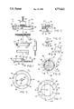
- FIG. 1 is an exploded cross sectional view of a retractable holder for an article
- FIG. 2 is a cross sectional detail of a locking means for the retractable holder shown in FIG. 1;
- FIG. 3 is a side view of the locking member
- FIG. 4 is a top view of the locking member
- FIG. 5 is a top view of the bottom housing member
- FIG. 6 is a bottom view of the spring holder
- FIG. 7 is a bottom view of the upper housing member.
- FIG. 1 An exploded cross sectional view of the retractable holder of the present invention is shown in FIG. 1.
- the housing 10 of the retractable holder includes a first housing member 12, and second housing member 14.
- the first wall 16 has a first slot 24 spaced inwardly from the peripheral side wall 18.
- a fastening stud 20 is integrally formed with the first wall 16 of the first housing member 12.
- a central aperture 28 is also formed in the first wall 16 of the housing 10.
- a retaining ridge 22 is formed integrally to the first wall 16 of the first housing member 12 which assists in retaining a rotatable holder 34 within the housing 10.
- the second housing member 14, as shown in FIGS. 1 and 5, has a second wall 44 disposed generally parallel to the first wall 16 of the first housing member 12.
- the second housing member 14 also includes a peripheral outer wall 46 and inner wall 48.
- the inner wall 48 can define a central aperture 50 which is aligned with the central aperture 28 in the first wall 16 of the first housing member 12.
- the central apertures, 28 and 50 respectively, can be used to attach means for holding an article 70, such as a gauge device, adjacent to the housing 10 for storage.
- the holding means can be a clip 64, such as the spring clip as disclosed in U.S. Pat. No. 1,711,730, a hook, a magnetic, or the like depending on the article 70 to be stored.
- the central aperture 28 and 50 respectively, can also be used to attach means for mounting the retractable holder in a desired location, such as clip, clamp, or hook for mounting the housing 10 adjacent to the machine apparatus, or for attaching to the belt of the operator.
- a third slot 58 is formed in the peripheral outer wall 46 of the second housing member 14. When the first housing member 12 is connected to the second housing member 14, the second slot 26 is aligned with the third slot 58 to form an opening through the peripheral side walls, 18 and 46 respectively, to a hollow inner compartment within the housing 10.
- a second retaining ridge 54 is formed integrally with the second wall 44 of the second housing member 14 and is aligned with the first retaining ridge 22 of the first housing member 12 to retain a rotatable holder 34.
- the second housing member 14 includes fastening apertures 52 in the second wall 44.
- the aperture 52 is aligned with the fastening stud 20 of the first housing member 12, such that the fastening stud 20 will pass through the aperture 52 when the second and third slot, 26 and 58, respectively, are aligned.
- the first and second housing members, 12 and 14 respectively are constructed of plastic. This permits the fastening stud 20 to be heat staked to hold the first and second housing members together. It should be apparent that other means for securing the first and second housing members, 12 and 14 respectively, are included within the scope of the invention.
- the fastening stud 20 can be threaded and a fastening nut can be attached thereto to secure the first housing member 12 to the second housing member 14, or a fastening member, for example a bolt 30 and a nut 32, can be passed through the central apertures, 28 and 50 respectively, to connect the first and second housing members together.
- the holder 34 has a central aperture 36 and is rotatably connected to the inner wall 48 of the second housing member 14.
- the holder 34 includes a third wall 38 and a peripheral side wall 40.
- the holder 34 rotates about the inner wall 48 of the second housing member 14 and is retained by the first and second retaining ridges, 22 and 54 respectively, formed on the first and second housing members, 12 and 14 respectively.
- the third wall 38 is disposed generally parallel to the first and second walls, 16 and 44 respectively, of the housing 10.
- the third peripheral side wall 40 is disposed generally perpendicular to the first and second walls 16 and 44, respectively.
- the third peripheral side wall 40 is spaced inwardly from the first and second peripheral sidewalls, 18 and 46 respectively, of the first and second housing members, 12 and 14 respectively.
- the flexible attaching means is extendable externally from the housing 10 through the second and third slots, 26 and 58 respectively, in the first and second sidewalls, 18 and 46 respectively.
- the flexible attaching means generally includes an attachment member 72 having a generally circular cross-section and a finite length.
- the attachment member 72 is anchored at one end to the holder 34 and connected at another end to the article 70.
- the member attachment 72 is coiled around the third peripheral side wall 40 of the holder 34 for storage within the hollow inner compartment of the housing 10. It should be apparent that attachment member 72 can be selected from a group consisting of a cable, cord, wire, string, rope, filament, fiber, and thread. As shown in FIGS. 1 and 6, the attachment member 72 of the present invention is connected to the holder 34 through an anchoring aperture 42 in the third peripheral side wall 40.
- the retracting means can include a coil spring 74 retained within the third peripheral side wall 46 of the holder 34. Suitable spring connections, 66 and 68, are formed on the third peripheral side wall 46 of the holder 34 and the inner wall 48 of the second housing member 14.
- the coil spring 74 biases the holder 34 to rotate in an attaching-means-retracting direction.
- the invention preferably includes means for locking the retracting means with the flexible attaching means extended in a desired position.
- the locking means can include a locking member 76, as shown in FIGS. 1 through 4.
- the locking member 76 is disposed in the first slot 24 of the first housing member 12 with one end extending externally to the housing 10 and another end slidingly engaging the third wall and third peripheral side wall, 38 and 40 respectively, of the holder 34.
- At least one notch 78 shown in FIGS. 1, 2, and 6, is formed in the third wall 38 adjacent the third peripheral side wall 40 of the holder 34.
- the notch 78 is intermittently disposed adjacent the first slot 24 in the first wall 16 of the first housing member 12 as the holder 34 rotates.
- the locking member 76 includes a flared portion 82 external from the housing 10, and a protruding portion 84 within the housing 10 to retain the locking member 76 in the first slot 24 of the first housing member 12.
- the first housing member 12 encloses the second housing member 14 with the first peripheral side wall 18 disposed externally of the second peripheral side wall 46, the fastening stud 20 aligned to pass through the fastening aperture 52 in the second housing member 14, and the second slot 26 aligned with the third slot 58 forming an opening from the hollow inner compartment of the housing 10.
- the holder 34 is rotatably connected to the inner wall 48.
- a coil spring 74 is retained within the holder 34 and is connected to the third peripheral side wall 40 at one end and the inner wall 48 at another end.
- the attachment member 72 is anchored to the holder 34 within the housing 10 at one end and attached to an article 70 at another end external to the housing 10. The attachment member 72 passes through the opening defined by the aligned second slot 26 and third slot 58.
- a finite length of the attachment member 72 is coiled around the third peripheral side wall 40 of the holder 34 and stored within the hollow inner compartment of the housing 10.
- the article 70 can be removed from the storage clip 64 when needed.
- the attachment member 72 is pulled out of the housing 10 through the opening defined by the second and third slots, 26 and 58 respectively.
- the holder 34 rotates which tightens the coil spring 74 through the suitable spring connections, 66 and 68 respectively.
- the locking member 76 slidingly engages the third wall and third peripheral side wall 38 and 40 respectively.
- the rotational velocity of the holder 34 slows, thereby permitting locking member 76 to engage within notch 78 to restrain the holder 34 against further rotation in either direction.
- the locking member 76 can be disengaged by pulling upward on the locking member 76, or by pulling out a small additional length of attachment member 72, the locking member 76 will be disengaged from notch 78 and the dispensed length of attachment member 72 can be retracted into its stored position coiled around the third peripheral side wall 40 of the holder 34 within the hollow inner compartment of the housing 10.
Landscapes
- Vehicle Step Arrangements And Article Storage (AREA)
Abstract
Description
Claims (11)
Priority Applications (1)
| Application Number | Priority Date | Filing Date | Title |
|---|---|---|---|
| US07/033,650 US4773623A (en) | 1987-04-03 | 1987-04-03 | Retractable holder for an article |
Applications Claiming Priority (1)
| Application Number | Priority Date | Filing Date | Title |
|---|---|---|---|
| US07/033,650 US4773623A (en) | 1987-04-03 | 1987-04-03 | Retractable holder for an article |
Publications (1)
| Publication Number | Publication Date |
|---|---|
| US4773623A true US4773623A (en) | 1988-09-27 |
Family
ID=21871635
Family Applications (1)
| Application Number | Title | Priority Date | Filing Date |
|---|---|---|---|
| US07/033,650 Expired - Fee Related US4773623A (en) | 1987-04-03 | 1987-04-03 | Retractable holder for an article |
Country Status (1)
| Country | Link |
|---|---|
| US (1) | US4773623A (en) |
Cited By (11)
| Publication number | Priority date | Publication date | Assignee | Title |
|---|---|---|---|---|
| US5077936A (en) * | 1989-09-29 | 1992-01-07 | Beaven David G P | Adjustable hanging basket |
| US5377626A (en) * | 1993-05-10 | 1995-01-03 | Kilsby; Celia | Lunge line controller |
| US5669571A (en) * | 1995-12-04 | 1997-09-23 | Graybill; Larry Dean | Electrical cord storage and dispensing organizer |
| US5762281A (en) * | 1997-02-18 | 1998-06-09 | Foley; Michael | Automatically loading cord winder apparatus and method |
| US6199784B1 (en) * | 1999-07-19 | 2001-03-13 | Ceramate Technical Co., Ltd. | Automatically rewindable wire device |
| US6199785B1 (en) * | 1999-09-28 | 2001-03-13 | Edward C. Paugh | Ratchet mechanism for a reel |
| US20030137835A1 (en) * | 2002-01-22 | 2003-07-24 | Alejandro Mier-Langner | Luminaire pendant system |
| US6792893B1 (en) | 2003-01-28 | 2004-09-21 | Diane Ellen Quintero | Retractable two-pet leash |
| US20050173917A1 (en) * | 2003-12-31 | 2005-08-11 | Eric Kovall | Retractable retention device and device retaining accessory and method for use |
| US20050194486A1 (en) * | 2004-03-04 | 2005-09-08 | Chien-Pin Huang | Signal cable rewinder with two rewinding discs |
| US10746388B2 (en) | 2016-08-30 | 2020-08-18 | Jasco Products Company LLC | Light source with integrated cable management system |
Citations (8)
| Publication number | Priority date | Publication date | Assignee | Title |
|---|---|---|---|---|
| US458769A (en) * | 1891-09-01 | Electric-light fixture | ||
| US727370A (en) * | 1903-02-02 | 1903-05-05 | Israel V Edgerton | Spring-reel. |
| US870908A (en) * | 1906-12-14 | 1907-11-12 | Zalmon G Sholes | Attachment for automobiles. |
| US887689A (en) * | 1907-10-24 | 1908-05-12 | Gaius M Brumbaugh | Reel-holder. |
| US1256016A (en) * | 1917-06-27 | 1918-02-12 | Peter Henderson | Spring-reel. |
| US1711730A (en) * | 1927-11-09 | 1929-05-07 | Francis W Gibson | Spring clip |
| US4202510A (en) * | 1978-12-04 | 1980-05-13 | Stanish Walter F | Retractable pet leash |
| US4556184A (en) * | 1983-08-08 | 1985-12-03 | Sullivan Daniel J O | Extendible ceiling hook |
-
1987
- 1987-04-03 US US07/033,650 patent/US4773623A/en not_active Expired - Fee Related
Patent Citations (8)
| Publication number | Priority date | Publication date | Assignee | Title |
|---|---|---|---|---|
| US458769A (en) * | 1891-09-01 | Electric-light fixture | ||
| US727370A (en) * | 1903-02-02 | 1903-05-05 | Israel V Edgerton | Spring-reel. |
| US870908A (en) * | 1906-12-14 | 1907-11-12 | Zalmon G Sholes | Attachment for automobiles. |
| US887689A (en) * | 1907-10-24 | 1908-05-12 | Gaius M Brumbaugh | Reel-holder. |
| US1256016A (en) * | 1917-06-27 | 1918-02-12 | Peter Henderson | Spring-reel. |
| US1711730A (en) * | 1927-11-09 | 1929-05-07 | Francis W Gibson | Spring clip |
| US4202510A (en) * | 1978-12-04 | 1980-05-13 | Stanish Walter F | Retractable pet leash |
| US4556184A (en) * | 1983-08-08 | 1985-12-03 | Sullivan Daniel J O | Extendible ceiling hook |
Cited By (13)
| Publication number | Priority date | Publication date | Assignee | Title |
|---|---|---|---|---|
| US5077936A (en) * | 1989-09-29 | 1992-01-07 | Beaven David G P | Adjustable hanging basket |
| US5377626A (en) * | 1993-05-10 | 1995-01-03 | Kilsby; Celia | Lunge line controller |
| US5669571A (en) * | 1995-12-04 | 1997-09-23 | Graybill; Larry Dean | Electrical cord storage and dispensing organizer |
| US5762281A (en) * | 1997-02-18 | 1998-06-09 | Foley; Michael | Automatically loading cord winder apparatus and method |
| US6199784B1 (en) * | 1999-07-19 | 2001-03-13 | Ceramate Technical Co., Ltd. | Automatically rewindable wire device |
| US6199785B1 (en) * | 1999-09-28 | 2001-03-13 | Edward C. Paugh | Ratchet mechanism for a reel |
| US20030137835A1 (en) * | 2002-01-22 | 2003-07-24 | Alejandro Mier-Langner | Luminaire pendant system |
| US6843581B2 (en) | 2002-01-22 | 2005-01-18 | Genlyte Thomas Group Llc | Luminaire pendant system |
| US6792893B1 (en) | 2003-01-28 | 2004-09-21 | Diane Ellen Quintero | Retractable two-pet leash |
| US20050173917A1 (en) * | 2003-12-31 | 2005-08-11 | Eric Kovall | Retractable retention device and device retaining accessory and method for use |
| US20050194486A1 (en) * | 2004-03-04 | 2005-09-08 | Chien-Pin Huang | Signal cable rewinder with two rewinding discs |
| US7201342B2 (en) * | 2004-03-04 | 2007-04-10 | Chien-Pin Huang | Signal cable rewinder with two rewinding discs |
| US10746388B2 (en) | 2016-08-30 | 2020-08-18 | Jasco Products Company LLC | Light source with integrated cable management system |
Similar Documents
| Publication | Publication Date | Title |
|---|---|---|
| US4773623A (en) | Retractable holder for an article | |
| US6484958B1 (en) | Patch cord caddy | |
| US5348240A (en) | Device for winding and storage of cords | |
| US4991265A (en) | Cord tie device | |
| US4989805A (en) | Retractable reel assembly for telephone extension cord | |
| US4126024A (en) | Bicycle cable lock | |
| US6098748A (en) | Adjustable height tool bin system | |
| US4226394A (en) | Adjustable mounting arrangement for hooks and the like | |
| US4586675A (en) | Tangle free cord holder | |
| US6349893B1 (en) | Retractable fiber slack storage device | |
| US6322279B1 (en) | Adjustable attachment device | |
| US4337934A (en) | Assembly post | |
| US4261529A (en) | Device for winding and storage of ropes and the like | |
| US5762281A (en) | Automatically loading cord winder apparatus and method | |
| EP1472504B1 (en) | Tape locking device for tape measure | |
| US5897039A (en) | Retractable strap | |
| US7395984B2 (en) | Safety tether for hand tools | |
| US3990279A (en) | Bi-circle lock | |
| US5423516A (en) | Fish tape reel | |
| PL169923B1 (en) | Apparatus for taking in and storing cargo immobilising belts especially for use in vehicles | |
| US20040245362A1 (en) | String of lights reel | |
| US5320398A (en) | Tie-down mechanism for automobile trunk lid | |
| US5139210A (en) | Dispensing assembly and method for coiled electrical wire | |
| US6550708B2 (en) | Device for a wound wire that is relatively stiff | |
| US3502281A (en) | Thread canister |
Legal Events
| Date | Code | Title | Description |
|---|---|---|---|
| AS | Assignment |
Owner name: RECOIL DISTRIBUTORS COMPANY, 31739 MOUND ROAD, WAR Free format text: ASSIGNMENT OF ASSIGNORS INTEREST.;ASSIGNOR:NABINGER, RICHARD;REEL/FRAME:004687/0115 Effective date: 19870320 Owner name: RECOIL DISTRIBUTORS COMPANY,MICHIGAN Free format text: ASSIGNMENT OF ASSIGNORS INTEREST;ASSIGNOR:NABINGER, RICHARD;REEL/FRAME:004687/0115 Effective date: 19870320 |
|
| AS | Assignment |
Owner name: ANSWER COMPANY, THE, 31739 MOUND ROAD, WARREN, MIC Free format text: ASSIGNMENT OF ASSIGNORS INTEREST.;ASSIGNOR:RECOIL DISTRIBUTORS COMPANY;REEL/FRAME:004763/0608 Effective date: 19870906 Owner name: ANSWER COMPANY, THE,MICHIGAN Free format text: ASSIGNMENT OF ASSIGNORS INTEREST;ASSIGNOR:RECOIL DISTRIBUTORS COMPANY;REEL/FRAME:004763/0608 Effective date: 19870906 |
|
| REMI | Maintenance fee reminder mailed | ||
| LAPS | Lapse for failure to pay maintenance fees | ||
| FP | Lapsed due to failure to pay maintenance fee |
Effective date: 19920927 |
|
| STCH | Information on status: patent discontinuation |
Free format text: PATENT EXPIRED DUE TO NONPAYMENT OF MAINTENANCE FEES UNDER 37 CFR 1.362 |