US477159A - Power-hammer - Google Patents
Power-hammer Download PDFInfo
- Publication number
- US477159A US477159A US477159DA US477159A US 477159 A US477159 A US 477159A US 477159D A US477159D A US 477159DA US 477159 A US477159 A US 477159A
- Authority
- US
- United States
- Prior art keywords
- hammer
- disk
- helve
- crank
- pivoted
- Prior art date
- Legal status (The legal status is an assumption and is not a legal conclusion. Google has not performed a legal analysis and makes no representation as to the accuracy of the status listed.)
- Expired - Lifetime
Links
Images

Classifications
-
- F—MECHANICAL ENGINEERING; LIGHTING; HEATING; WEAPONS; BLASTING
- F16—ENGINEERING ELEMENTS AND UNITS; GENERAL MEASURES FOR PRODUCING AND MAINTAINING EFFECTIVE FUNCTIONING OF MACHINES OR INSTALLATIONS; THERMAL INSULATION IN GENERAL
- F16H—GEARING
- F16H19/00—Gearings comprising essentially only toothed gears or friction members and not capable of conveying indefinitely-continuing rotary motion
- F16H19/02—Gearings comprising essentially only toothed gears or friction members and not capable of conveying indefinitely-continuing rotary motion for interconverting rotary or oscillating motion and reciprocating motion
- F16H19/025—Gearings comprising essentially only toothed gears or friction members and not capable of conveying indefinitely-continuing rotary motion for interconverting rotary or oscillating motion and reciprocating motion comprising a friction shaft
-
- Y—GENERAL TAGGING OF NEW TECHNOLOGICAL DEVELOPMENTS; GENERAL TAGGING OF CROSS-SECTIONAL TECHNOLOGIES SPANNING OVER SEVERAL SECTIONS OF THE IPC; TECHNICAL SUBJECTS COVERED BY FORMER USPC CROSS-REFERENCE ART COLLECTIONS [XRACs] AND DIGESTS
- Y10—TECHNICAL SUBJECTS COVERED BY FORMER USPC
- Y10T—TECHNICAL SUBJECTS COVERED BY FORMER US CLASSIFICATION
- Y10T74/00—Machine element or mechanism
- Y10T74/18—Mechanical movements
- Y10T74/18056—Rotary to or from reciprocating or oscillating
Definitions
- our invention relates to improvements in power-hammers and.
- the object of our invention is to produce a powenhammer in which all the movable parts work from a common center, so as to enable the machine to be eas ily adjusted; which is nicely balanced, so that it may be run with little power, and consequently be worked by hand or foot power; which is provided with a counterbalanced hammer or die and has means for adjustment, so that the blow may be harder in either direction, as desired; which is provided with a substantially frictionless means for raising and lowering ⁇ the hammer; which is adapted to give an elastic blow in imitation of handwerk, and which may be quickly adjusted to operate conveniently7 on different thicknesses of material.
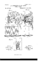
- Figure 1 is a side elevation of the machine.
- Fig. 2 is a front elevation of the same.
- Fig. 3 is a broken plan viewof the machine. Fig.
- et is a vertical longitudinal section.
- Fig. 5 is a broken rear elevation, partly7 in section; and
- Fig. G is a detail View showing the connection between the sliding hammer-head and. the segment which carries it.
- the machine is provided with a substantial frame 10, in the upper part of which is a transverse shaft 11, driven by a pulley 12, secured to one end and having loosely mounted on the opposite end a large disk 13, which disk has an elongated hub 13, extending through the machine-frame, and there will be friction enough on the hub under ordinary circumstances to hold the disk in the position in which it is placed; but to guard against any possible deviation the disk is provided with a depending handle 14, which is firmly secured to it and which carries a common form of spring-lateh 1G, adapted to engage a toothed rack 15, which is arranged opposite the latch and secured to the machine-frame.
- crank-plate 17 On the end of the shaft 11 which projects through the disk 13 is a crank-plate 17, having a crank-pin 1S, on which is pivoted a connecting-rod 19, which rod has its opposite end pivoted to a sliding plate 20, which moves in aslideway 2l, formed on the outer surface of the disk 13.
- the sliding plate 2O is connected with one arm 22 of a double crank 23, which crank is journalcd in a lever 2%, said lever being pivoted on the outer side of the disk near its upper periphery and extending tangentially across the disk and below the same to a point where it may be conveniently reached, at which point it is formed into a handle 25, having a spring-latch 16, adapted to engage a toothed rack and hold the lever in a desired position.
- the arm 22 of the double crank is slotted near its free end, as shown at 26, so as to permit the necessary play of the pin connecting it with the sliding plate 20, and the crank is braced by a brace 24, pivoted to the inner side of the disk at a point opposite the upper end of the lever 24, the lower end of the brace being secured to the crank-pin.
- the disk is slotted, as shown at 27, to permit the necessary movement of the crank 23 and lever 24.
- the inner arm 28 of the double crank 23 extends rearward in a direction opposite to that of the arm 22 and connects with a depending arm 29 on the helve 30, which helve is pivoted centrally on the elongated hub 13a' et' the disk 13 and has at its frontend two verticallyaligning guide-pieces 3l, between which is a strong flat spring 32, one end of which is rigidly secured in the front end of the helve 30 and the opposite end of which is attached to a segmental plate 33, the arms 34 of which are pivoted on the hub 13J and shaft 11, as best shown in Figs. a and 5.
- this segmental plate 33 In front of this segmental plate 33 is a vertically-slidin g head 35, which moves in a slideway formed in the uprights 36 of the main frame, and this head carries the hammer or die 37.
- the head and segmental plate are connected by means of straps 38, the middle one of which is secured at its upper end to the top edge of IOO the head and at its lower end to the lowery edge-of the plate, and the other two straps' have their upper ends secured to the upper edge of the plate and their lower ends secured to the bottom edge of the head.
- Beneath the hammer 37 is the lower die oranvil 39, and the material to be opererated upon is placed upon the lower die or. anvil, so as to receive the blows from the hammer above.
- a coun-1 terbalancing-weight 40 which is adapted to connterbalance the hammer 37 and which may, be adjusted longitudinally upon the helve 30.; It will'thus be seen thatJthe-hammer may -be exactly balanced or theweight may be ad,l justed so that the hammerwill move downor, up with greater or vless force, as desired.
- the operation of the machine is as followszi
- the machine is first adjusted so that the ham-f mer 37 will be normally at a desired dis-1 tance above the anvil 39 by means of the handle 14. This is done by merely moving. thehandlebaokward or forward, as the move- ⁇ ment of the handle turns the ⁇ disk and causes? it to more the'crank 23, and thus raise or; lower the rear end of the helve 30, as the; casemay be, and so bring the hammer into a desired position.
- the machine is then@l started and the rotary movement of the shaftf.
- crank-plate 17 causes the conneoting- ⁇ rod 19 and slide-plate 2O to move up andi down, and the movement of the slidefplate oscillates the crank 23, and consequently tilts.v the helve 30, which movement of the helve,v moves the segmental plate 33, by means of thee spring 32, and thus raises andlowers the ham ⁇ mer-head 35 and hammer 37, and the spring: connection between the helve and segment ⁇ causes an elastic blow to be struck.
- the lever 24 is moved backward or forward, so as to move the crank 23 into a desired position in.' the slot 27 and it will be readily understood. ⁇ that the stroke will vary, according as the ⁇ crank is Vpushed into the slot or near the open end of the same, as the-inner end of the slot'.J is much nearer the center of the disk than the outer end.
- the lever 24 may be movedh1 easily-and with safety while the machine is in operation, and, as a result, the hammer may be made to deliver powerful strokes during the early stages of an operation, and the strokes may be gradually diminished in power until they may be as light as desired.
- the hammer may be made to deliver a blow in any direction by simply changing the shape of the frame and the direction of the slideway of the hammer, consequently the machine is well adapted to be mounted on a tripod and operate a drill.
- a power-'hammer comprising a disk arranged vertically and made adjustable around its axis, a plate held and adapted to reciprocate in a slideway arranged on a face of said disk, a driving-shaft arranged at a .right angle to the disk, a helve pivoted on the latter and operating vertically, a hammer fixed on the outer end of such helve, and means for connecting the sliding plate with the ⁇ helve and also with thedriving-shaft, as shown and described.
- the disk In a powerhammer apparatusthe coinbination, with the driving-shaft, the hammer and its helve pivoted on the driving-shaft, the disk also pivoted on the shaft and thus made adjustable aroundit, of thelever 24, pivoted to said disk and adapted for adjustment for the purpose stated,.1neans for locking said lever, and means for connecting it with the hammerhelve, substantially as shown and described, whereby the throw of the hammer may be regulated, as specified.
Landscapes
- Engineering & Computer Science (AREA)
- General Engineering & Computer Science (AREA)
- Mechanical Engineering (AREA)
- Percussive Tools And Related Accessories (AREA)
Description
(No Model.) 2 Sheets-Sheet. 1. J. B. SWBE-NBY 85 R. W; LAIRD.
POWER HAMMER.
Patented June 14, 1892.
W/T/VESSES:
I@ 7 a i? ZZ 1 mams Pneus an., mor wnsnmsfow. u. c.
(No Model.) 2Sheets-Sheet 2. J. B. SWEBNEY 8v R. W. LAIRD.
POWER HAMMER.
No. 477,159. Patented June 14, 1892..
UNITED STATES PATENT OFFICE.
JAMES B. S\VEENEY AND ROBER" XV. LARD, OF ST. JOIINSBURY, VERMONT.
POWER-HAMMER.
SPECIFICATION forming part of Letters Patent No. 477,159, dated .T une 14, 1892. Application tiled July 21, 1891. Serial No. l200,210. (No model.)
.To all whom t may concern:
Be it known that we, JAMES B. SWEENEY and ROBERT \V. LAIRD, both of St. Johnsbury, in the county of Caledonia and State of Vermont, have invented a new and Improved Power-Hammer, of which the following is a full, clear, and exact description.
Our invention relates to improvements in power-hammers and. the object of our invention is to produce a powenhammer in which all the movable parts work from a common center, so as to enable the machine to be eas ily adjusted; which is nicely balanced, so that it may be run with little power, and consequently be worked by hand or foot power; which is provided with a counterbalanced hammer or die and has means for adjustment, so that the blow may be harder in either direction, as desired; which is provided with a substantially frictionless means for raising and lowering` the hammer; which is adapted to give an elastic blow in imitation of handwerk, and which may be quickly adjusted to operate conveniently7 on different thicknesses of material.
To this end our invention consists in eertain features of construction and combination of parts, which will be hereinafter described and claimed.
Reference is to be had to the accompanying drawings, forming a part of this specification, in which similar gures of reference indicate corresponding parts in all the views.
Figure 1 is a side elevation of the machine.
Fig. 2 is a front elevation of the same. Fig. 3 is a broken plan viewof the machine. Fig.
et is a vertical longitudinal section. Fig. 5 is a broken rear elevation, partly7 in section; and Fig. G is a detail View showing the connection between the sliding hammer-head and. the segment which carries it.
The machine is provided with a substantial frame 10, in the upper part of which is a transverse shaft 11, driven by a pulley 12, secured to one end and having loosely mounted on the opposite end a large disk 13, which disk has an elongated hub 13, extending through the machine-frame, and there will be friction enough on the hub under ordinary circumstances to hold the disk in the position in which it is placed; but to guard against any possible deviation the disk is provided with a depending handle 14, which is firmly secured to it and which carries a common form of spring-lateh 1G, adapted to engage a toothed rack 15, which is arranged opposite the latch and secured to the machine-frame.
On the end of the shaft 11 which projects through the disk 13 is a crank-plate 17, having a crank-pin 1S, on which is pivoted a connecting-rod 19, which rod has its opposite end pivoted to a sliding plate 20, which moves in aslideway 2l, formed on the outer surface of the disk 13. The sliding plate 2O is connected with one arm 22 of a double crank 23, which crank is journalcd in a lever 2%, said lever being pivoted on the outer side of the disk near its upper periphery and extending tangentially across the disk and below the same to a point where it may be conveniently reached, at which point it is formed into a handle 25, having a spring-latch 16, adapted to engage a toothed rack and hold the lever in a desired position.
The arm 22 of the double crank is slotted near its free end, as shown at 26, so as to permit the necessary play of the pin connecting it with the sliding plate 20, and the crank is braced by a brace 24, pivoted to the inner side of the disk at a point opposite the upper end of the lever 24, the lower end of the brace being secured to the crank-pin. The disk is slotted, as shown at 27, to permit the necessary movement of the crank 23 and lever 24. The inner arm 28 of the double crank 23 extends rearward in a direction opposite to that of the arm 22 and connects with a depending arm 29 on the helve 30, which helve is pivoted centrally on the elongated hub 13a' et' the disk 13 and has at its frontend two verticallyaligning guide-pieces 3l, between which is a strong flat spring 32, one end of which is rigidly secured in the front end of the helve 30 and the opposite end of which is attached to a segmental plate 33, the arms 34 of which are pivoted on the hub 13J and shaft 11, as best shown in Figs. a and 5. In front of this segmental plate 33 is a vertically-slidin g head 35, which moves in a slideway formed in the uprights 36 of the main frame, and this head carries the hammer or die 37. The head and segmental plate are connected by means of straps 38, the middle one of which is secured at its upper end to the top edge of IOO the head and at its lower end to the lowery edge-of the plate, and the other two straps' have their upper ends secured to the upper edge of the plate and their lower ends secured to the bottom edge of the head. This attaclr ment permits of a frictionless movement of the segment and head in relation to each other as the straps will alternately be wound and unwound; but instead of connecting the parts by means of straps chains, gears, or other suitable means may be employed for moving the head by the movement of the seg#= ment. Beneath the hammer 37 is the lower die oranvil 39, and the material to be opererated upon is placed upon the lower die or. anvil, so as to receive the blows from the hammer above.
-On therear end of the helve 30 is a coun-1 terbalancing-weight 40, which is adapted to connterbalance the hammer 37 and which may, be adjusted longitudinally upon the helve 30.; It will'thus be seen thatJthe-hammer may -be exactly balanced or theweight may be ad,l justed so that the hammerwill move downor, up with greater or vless force, as desired.
The operation of the machine is as followszi The machineis first adjusted so that the ham-f mer 37 will be normally at a desired dis-1 tance above the anvil 39 by means of the handle 14. This is done by merely moving. thehandlebaokward or forward, as the move- `ment of the handle turns the `disk and causes? it to more the'crank 23, and thus raise or; lower the rear end of the helve 30, as the; casemay be, and so bring the hammer into a desired position. The machine is then@l started and the rotary movement of the shaftf. 11 and crank-plate 17 causes the conneoting-` rod 19 and slide-plate 2O to move up andi down, and the movement of the slidefplate oscillates the crank 23, and consequently tilts.v the helve 30, which movement of the helve,v moves the segmental plate 33, by means of thee spring 32, and thus raises andlowers the ham` mer-head 35 and hammer 37, and the spring: connection between the helve and segment` causes an elastic blow to be struck. To; change the stroke of the hammer, the lever 24 is moved backward or forward, so as to move the crank 23 into a desired position in.' the slot 27 and it will be readily understood.` that the stroke will vary, according as the` crank is Vpushed into the slot or near the open end of the same, as the-inner end of the slot'.J is much nearer the center of the disk than the outer end. The lever 24 may be movedh1 easily-and with safety while the machine is in operation, and, as a result, the hammer may be made to deliver powerful strokes during the early stages of an operation, and the strokes may be gradually diminished in power until they may be as light as desired.
It will be noticed that the main disk, the
helve, and the main operating parts of the machine are mounted on a common shaft, and as a result the hammer may be made to deliver a blow in any direction by simply changing the shape of the frame and the direction of the slideway of the hammer, consequently the machine is well adapted to be mounted on a tripod and operate a drill.
Having thus fully described our invention, we claim as new and desire to secure byLetters Patent- 1. A power-'hammer comprising a disk arranged vertically and made adjustable around its axis, a plate held and adapted to reciprocate in a slideway arranged on a face of said disk, a driving-shaft arranged at a .right angle to the disk, a helve pivoted on the latter and operating vertically, a hammer fixed on the outer end of such helve, and means for connecting the sliding plate with the `helve and also with thedriving-shaft, as shown and described.
2. In a powerhammer apparatus, the combination of a pivoted helve, a segment attached to one end of the latter and having a spring connection .with it, a reciprocating hammer and guides therefor, and straps attached to the segment and hammer at their respective ends, all operating as shown and described.
3. In a powerhammer apparatusthe coinbination, with the driving-shaft, the hammer and its helve pivoted on the driving-shaft, the disk also pivoted on the shaft and thus made adjustable aroundit, of thelever 24, pivoted to said disk and adapted for adjustment for the purpose stated,.1neans for locking said lever, and means for connecting it with the hammerhelve, substantially as shown and described, whereby the throw of the hammer may be regulated, as specified.
4. The combination, with the main frame, having a suitable driving-shaft therein, the tilting helve mounted on the shaft, and the hammer connected with and operated by the helve, of the disk mounted loosely on the shaft, the slide-plate mounted on the disk and having a crank connection with the driving-shaft., a lever pivoted on the disk, and a two-armed crank journaled in the lever and whose journal is arranged in a slot in the disk, one arm of the crank being secured to the slide-plate and the opposite arm connected with the rear end of the tilting helve, substantially as described.
J AMES B. SWEENEY. ROBERT W. LAIRD. Witnesses:
FRANK STAFFORD, WENDELL P. STAFFORD.
Publications (1)
| Publication Number | Publication Date |
|---|---|
| US477159A true US477159A (en) | 1892-06-14 |
Family
ID=2546015
Family Applications (1)
| Application Number | Title | Priority Date | Filing Date |
|---|---|---|---|
| US477159D Expired - Lifetime US477159A (en) | Power-hammer |
Country Status (1)
| Country | Link |
|---|---|
| US (1) | US477159A (en) |
-
0
- US US477159D patent/US477159A/en not_active Expired - Lifetime
Similar Documents
| Publication | Publication Date | Title |
|---|---|---|
| US341664A (en) | Hand-tool | |
| US382230A (en) | Whip-button-rolling machine | |
| US318540A (en) | Machine for cutting boot and shoe soles | |
| US251804A (en) | steinbach | |
| US101788A (en) | Improvement in scroll-sawing machines | |
| US193026A (en) | Improvement in machines for punching and shearing metal | |
| US1166931A (en) | Machine for hammering wire-drawing dies. | |
| US133935A (en) | Improvement in nail-cutting machines | |
| USRE3839E (en) | Improvement in apparatus por scraping and working hides | |
| US311082A (en) | Stone-drilling machine | |
| US203441A (en) | Improvement in paper-cutting machines | |
| US1263267A (en) | Power-hammer. | |
| US57534A (en) | Improvement in machinery for cutting oval holes in boiler-heads | |
| US316073A (en) | Leather-cutting press | |
| US713566A (en) | Beading and turning machine. | |
| US9379A (en) | Peters | |
| US98013A (en) | Improvement in | |
| US67913A (en) | eoot and k | |
| US68298A (en) | gibbs | |
| US75131A (en) | Thomas b | |
| US992945A (en) | Mortising-machine. | |
| US117340A (en) | Improvement in sawing-machines | |
| US425988A (en) | crane | |
| US139442A (en) | Improvement in machines for staking, glassing, and perching skins | |
| US74187A (en) | Eupits weight |