US4771367A - Electric plug with circuit breaker - Google Patents

Electric plug with circuit breaker Download PDF

Info

Publication number
US4771367A
US4771367A US07/046,258 US4625887A US4771367A US 4771367 A US4771367 A US 4771367A US 4625887 A US4625887 A US 4625887A US 4771367 A US4771367 A US 4771367A
Authority
US
United States
Prior art keywords
power
plug
prongs
housing
circuit breaker
Prior art date
Legal status (The legal status is an assumption and is not a legal conclusion. Google has not performed a legal analysis and makes no representation as to the accuracy of the status listed.)
Expired - Fee Related
Application number
US07/046,258
Inventor
Michael J. Serr
Carlyle Serr
Lawrence E. Pierce
Current Assignee (The listed assignees may be inaccurate. Google has not performed a legal analysis and makes no representation or warranty as to the accuracy of the list.)
HIGH Q MANUFACTURING Co A CORP OF MI
HIGH Q Manufacturing Co
Original Assignee
HIGH Q Manufacturing Co
Priority date (The priority date is an assumption and is not a legal conclusion. Google has not performed a legal analysis and makes no representation as to the accuracy of the date listed.)
Filing date
Publication date
Application filed by HIGH Q Manufacturing Co filed Critical HIGH Q Manufacturing Co
Priority to US07/046,258 priority Critical patent/US4771367A/en
Assigned to HIGH Q MANUFACTURING CO., A CORP. OF MI reassignment HIGH Q MANUFACTURING CO., A CORP. OF MI ASSIGNMENT OF ASSIGNORS INTEREST. Assignors: PIERCE, LAWRENCE E., SERR, CARLYLE, SERR, MICHAEL J.
Application granted granted Critical
Publication of US4771367A publication Critical patent/US4771367A/en
Anticipated expiration legal-status Critical
Expired - Fee Related legal-status Critical Current

Links

Images

Classifications

    • HELECTRICITY
    • H01ELECTRIC ELEMENTS
    • H01RELECTRICALLY-CONDUCTIVE CONNECTIONS; STRUCTURAL ASSOCIATIONS OF A PLURALITY OF MUTUALLY-INSULATED ELECTRICAL CONNECTING ELEMENTS; COUPLING DEVICES; CURRENT COLLECTORS
    • H01R13/00Details of coupling devices of the kinds covered by groups H01R12/70 or H01R24/00 - H01R33/00
    • H01R13/66Structural association with built-in electrical component
    • H01R13/70Structural association with built-in electrical component with built-in switch
    • H01R13/713Structural association with built-in electrical component with built-in switch the switch being a safety switch
    • YGENERAL TAGGING OF NEW TECHNOLOGICAL DEVELOPMENTS; GENERAL TAGGING OF CROSS-SECTIONAL TECHNOLOGIES SPANNING OVER SEVERAL SECTIONS OF THE IPC; TECHNICAL SUBJECTS COVERED BY FORMER USPC CROSS-REFERENCE ART COLLECTIONS [XRACs] AND DIGESTS
    • Y10TECHNICAL SUBJECTS COVERED BY FORMER USPC
    • Y10STECHNICAL SUBJECTS COVERED BY FORMER USPC CROSS-REFERENCE ART COLLECTIONS [XRACs] AND DIGESTS
    • Y10S439/00Electrical connectors
    • Y10S439/954Special orientation of electrical connector

Definitions

  • the present invention relates to electric plugs, and more particularly to such plugs incorporating integral over-current protection such as circuit breakers.
  • a second type of electric safety plug is illustrated in U.S. Pat. Nos. 4,086,643 and Des. 246,241 issued Apr. 25, 1978 and Nov. 1, 1977, respectively, to Jacobs, entitled COMBINATION PLUG AND POWER CUT-OFF UNIT.
  • This plug includes a hollow multi-piece housing which supports the power cord connection, a circuit breaker, and the prong assembly. The breaker trips whenever excessive current is conducted through the prongs.
  • This plug also suffers several disadvantages. First, its profile is excessively large so that the assembly protrudes undesirably from the receptacle. Second, the multi-piece housing can come open exposing dangerous electric connections. Third, the many pieces required to assemble this plug create inventory and assembly problems.
  • a third type of electric safety plug is sold by The Belden Division of Cooper Industries located in Geneva, Ill.
  • This plug includes a plug body integrally molded over the end of a power cord and integrally supporting common and ground prongs.
  • the housing also defines a bayonet fuse socket.
  • a bayonet fuse with an integral power prong mounted thereon is releasably secured within the socket. If excessive current flows through the power prong, the integral fuse blows and power is interrupted.
  • the plug To reestablish the connection, the plug must be withdrawn from the outlet; the bayonet fuse must be removed; a proper bayonet replacement fuse must be located and reinstalled within the plug housing; and the plug must be reinserted into the outlet.
  • This plug has several drawbacks. First, the plug must be removed from the receptacle each time the fuse is to be checked or replaced. Second, an inventory of fuses must be maintained to provide replacement capability. Third, the plug is relatively expensive to operate since the fuse-and-prong assembly must continually
  • an electric safety plug including an integral circuit breaker in a low profile housing.
  • the plug includes an injection-molded housing molded directly onto the end of a power cord.
  • the housing integrally supports the plug prongs and also a circuit breaker connected in series with one of the prongs. All electric connections are encapsulated within the molded plug housing and therefore cannot become exposed during rough handling of the plug.
  • the relatively simple construction reduces the number of parts, and hence the cost, of the plug.
  • the housing is elongated, and the prongs extend from one of the elongated faces. Consequently, when the plug is installed within a outlet, the elongated plug body lies relatively flat against the wall. Further in this embodiment, the plug prongs are angularly oriented with respect to the elongated body so that the body will not overlie an adjacent outlet when mounted in a first outlet. This enables multiple plugs to be utilized side-by-side in duplex outlets.
  • these two features are combined to provide an integrally molded elongated plug housing which integrally supports the plug prongs and circuit breaker.
  • the power cord enters one end and the circuit breaker is positioned within the opposite end so that the plug has a low profile against the wall.
  • FIG. 1 is a perspective view of the electric safety plug
  • FIG. 2 is a front elevational view of the plug
  • FIG. 3 is a longitudinal sectional view through the plug
  • FIG. 4 is a front elevational view of the circuit breaker
  • FIG. 5 is a schematic diagram of the electric connections within the plug
  • FIG. 6 is an elevational view of two of the plugs mounted in a duplex outlet.
  • FIG. 7 is a top plan view of the plug housing only.
  • a safety electric plug constructed in accordance with a preferred aspect of the invention is illustrated in the drawings and generally designated 10.
  • the plug includes a plug housing or body 12, a prong assembly 14, and a circuit breaker or other over-current protection means 16.
  • the one-piece housing 12 is integrally molded onto the power cord 18 and integrally supports both the prong assembly 14 and the circuit breaker 16. Consequently, the present plug provides integral over-current protection in a compact low-profile assembly.
  • the housing 12 (FIGS. 1-3 and 7) is preferably injection molded to provide a unitary support mechanism for the remaining components.
  • the housing is elongated including a longitudinal axis 30 and includes opposite relatively narrow top and bottom ends 32 and 34.
  • the bottom end 34 is integrally molded onto the power cord 18 to provide a secure interconnection between the housing and power cord.
  • the cross-sectional configuration of the plug perpendicular to the axis 30 is generally rectangular so that the plug includes a front face 36, a rear face 38, and left and right faces 40 and 42. Gripping ridges 44 and 46 extend the full length of the left and right sides 40 and 42, respectively, to provide a mechanism by which the plug housing can be more easily grasped.
  • the housing 12 defines a chamber 50 (FIG. 3) which opens through the top end 32.
  • the chamber is generally elongated and oriented generally parallel to the axis 30.
  • the chamber 50 is generally square in cross section and extends from the top end 32 to a floor 52 which is approximately midway along the length of the housing 12.
  • a pair of slots 54a and 54b are defined in the floor 52 of the chamber 50 to receive prongs on the circuit breaker as will be described.
  • the perimeter 56 of the opening of the chamber 50 receives the face of the circuit breaker.
  • the power cord 18 (FIGS. 3 and 5) is generally well known to those having ordinary skill in the art. This is a three-conductor cord including power, common, and ground conductors.
  • the power cord 18 includes an insulating/protective jacket preferably of the same color as the housing 12.
  • the prong assembly 14 (FIGS. 1-2 and 5) is mounted within the front face 36 at a location proximate the bottom end 34.
  • the prong assembly includes a power prong 60, a power prong (also referred to as a common prong) 62, and a ground prong 64.
  • the prongs are fabricated of copper to provide good electric conductivity.
  • the prongs are electrically connected to the conductors within the power cord 18 as will be described.
  • the prongs are sized and arranged to interfit with a conventional receptacle outlet as is well known to those having ordinary skill in the art.
  • the housing 12 is integrally molded about the prongs such that the prongs are integrally and directly supported by the housing.
  • the prongs are generally perpendicular to the axis 30 (see FIG. 3). Further, an imaginary line 70 drawn through the two power prongs 60 and 62 forms an acute angle with the axis 30. Although an angle of approximately forty-five degrees is disclosed, this angle should be substantially nonperpendicular. Preferably, the angle should be in the range zero degrees to approximately forty-five degrees as will be described.
  • the circuit breaker 16 (FIGS. 3 and 4) are generally well known in the art and are typically referred to as panel breakers since they are most commonly installed within planar control panels.
  • the breaker used in the preferred embodiment is that sold by Mechanical Products, Inc. of Jackson, Mich. as the 2000 Series.
  • the breaker generally includes a body 80 defining a face 82 at one end and integrally supporting prongs 84 at its opposite end.
  • the breaker body is plastic and includes upper and lower spring fingers or other ratchet means 86 which lock the breaker within the chamber 50.
  • the prongs 84 interfit with the slots 542 and 546 in the floor 52 of the chamber 50 to make electric connection with the power conductor in the cord 18 through one slot and the power prong 60 through the other slot.
  • the breaker further includes a reset button 88 which can be depressed, or pushed in the direction of housing 12, to rest the breaker after it is tripped.
  • the breaker body 80 is generally closely received within the chamber 50.
  • the spring fingers 86 ratchet against the walls of the chamber 50 permitting the breaker to be slid into the chamber 50 during installation but not easily subsequently withdrawn.
  • the breaker capacity will be selected depending on the application. Currently anticipated capacities are in the range 0.25 to 15 amps.
  • the electric interconnections in the plug are schematically illustrated in FIG. 5.
  • the power cord 18 includes a power conductor 90, a common conductor 92, and a ground conductor 94.
  • the circuit breaker 16 is coupled in series with the power prong 60.
  • electric connections, (not specifically shown) are provided in sockets 54a and 54b by which means the circuit breaker 16 is connected with the power conductor 90 and the prong 60.
  • the common conductor 92 is coupled directly to the common prong 62, and the ground conductor 94 is coupled directly to the ground prong 64. All electric connections are made in a manner well-known in the art and are encapsulated within the integrally molded housing 12. The connections are therefore protected from exposure even upon rugged use of the housing.
  • Manufacture of the plug is initiated by making all electric connections which will be encapsulated within the plug housing 12. These connections are schematically illustrated in FIG. 5. Specifically, the power conductor 90 is coupled to one socket 54b, and the power prong 60 is coupled to the other socket 54a. The common wire 52 is coupled to the common prong 62; and the ground conductor 94 is coupled to the ground prong 64. The prong assembly 14 is then mounted within a mold insert which holds the prongs in position for subsequent molding. The insert can be rotated through 360 degrees so that the prong assembly 14 can be installed at any desired angular orientation to the housing axis 30.
  • the housing 12 is injection molded onto the power cord 18 and the prong assembly 14. During molding, all electric connections are encapsulated within the housing 12.
  • the circuit breaker 16 is installed within the chamber 50.
  • the prongs 84 slide into slots to establish electric connection with the power conductor 90 and the power prong 60 such that the circuit breaker is coupled in series with the power prong 60.
  • the fingers 86 engage the chamber walls and are slightly compressed thereby. Breaker insertion continues until the facing 82 extends slightly into perimeter 56. The compressed fingers 86 provide a ratcheting effect to prevent inadvertent removal of the breaker from the housing 12.
  • the plug can be mounted on any appliance power cord or in conjunction with any device requiring electric power.
  • the plug has its greatest utility in conjunction with appliances which draw large currents such as table saws or other devices with relatively large electric motors.
  • the circuit breaker 16 trips to interrupt power to the power prong 60 and consequently to the device powered by the cord. After corrective action has been taken to remedy the over-current situation, the breaker 16 is reset simply by depressing the reset button 88. The plug therefore provides infinitely resettable over-current protection for the appliance.
  • FIG. 6 The desirability of the angular orientation of the prong assembly 14 is illustrated in FIG. 6.
  • Two plugs 10a and 10b are illustrated mounted side-by-side within a conventional duplex outlet 100 including an upper outlet 102, a lower outlet 104, and a cover plate 106.
  • the angular orientation of the prong assemblies (not visible) of the plugs 10a and 10b orients the elongated plug housings 12a and 12b at an angle with respect to the receptacle 100. Consequently the elongated housings 12a and 12b do not overlap or otherwise restrict access to the adjacent outlets. If the angle between the line 70 and the axis 30 (FIG.
  • the housings 12a and 12b would undesirably overlie the adjacent receptacle outlets. Conversely, if the line 70 and the axis 30 are parallel, the housings 12a and 12b will be oriented generally horizontally. The optimal range for the angle between the line 70 and the axis 30 is in the range of zero degrees to approximately forty-five degrees to prevent this overlapping problem. In any event, the circuit breakers 16a and 16b of the plugs 10i a and 10b, respectively, are readily accessible for resetting even when the plugs are in the outlets.
  • the present plug provides a low profile plug with an integral circuit breaker.
  • the low profile enhances safety and the security of the plug within the receptacle.
  • the integral circuit breaker enables power to be easily reestablished without accessing the fuse box or circuit breaker box through which the circuit is connected.

Landscapes

  • Details Of Connecting Devices For Male And Female Coupling (AREA)

Abstract

The specification discloses an injection-molded electric plug having an integral circuit breaker. The plug housing is molded directly onto the power cord and defines a circuit breaker chamber. A circuit breaker is slidably received within the chamber and retained therein by spring fingers. The housing is elongated and the prongs extend from one of the long sides thereof so that the housing lays substantially flat against a receptacle. The prongs are angularly oriented with respect to the elongated body so that the body will not overlie adjacent receptacle outlets.

Description

BACKGROUND OF THE INVENTION
The present invention relates to electric plugs, and more particularly to such plugs incorporating integral over-current protection such as circuit breakers.
A wide variety of devices have been developed for providing over-current protection at the electric plug. One such approach is to provide a circuit breaker box interposed between a conventional electric plug and a conventional outlet receptacle. This device is disclosed in U.S. Pat. No. 4,484,185, issued Nov. 20, 1984, to Graves entitled SAFETY PLUG ADAPTOR. However, such devices protrude excessively from the outlet, creating safety problems and preventing appliances from being placed against the wall in which the plug is mounted. Further, the necessity of a separate box creates inventory and installation problems. Third, the box must be secured to the receptacle cover plate further complicating the construction and use of this device.
A second type of electric safety plug is illustrated in U.S. Pat. Nos. 4,086,643 and Des. 246,241 issued Apr. 25, 1978 and Nov. 1, 1977, respectively, to Jacobs, entitled COMBINATION PLUG AND POWER CUT-OFF UNIT. This plug includes a hollow multi-piece housing which supports the power cord connection, a circuit breaker, and the prong assembly. The breaker trips whenever excessive current is conducted through the prongs. This plug also suffers several disadvantages. First, its profile is excessively large so that the assembly protrudes undesirably from the receptacle. Second, the multi-piece housing can come open exposing dangerous electric connections. Third, the many pieces required to assemble this plug create inventory and assembly problems.
A third type of electric safety plug is sold by The Belden Division of Cooper Industries located in Geneva, Ill. This plug includes a plug body integrally molded over the end of a power cord and integrally supporting common and ground prongs. The housing also defines a bayonet fuse socket. A bayonet fuse with an integral power prong mounted thereon is releasably secured within the socket. If excessive current flows through the power prong, the integral fuse blows and power is interrupted. To reestablish the connection, the plug must be withdrawn from the outlet; the bayonet fuse must be removed; a proper bayonet replacement fuse must be located and reinstalled within the plug housing; and the plug must be reinserted into the outlet. This plug has several drawbacks. First, the plug must be removed from the receptacle each time the fuse is to be checked or replaced. Second, an inventory of fuses must be maintained to provide replacement capability. Third, the plug is relatively expensive to operate since the fuse-and-prong assembly must continually be replaced.
SUMMARY OF THE INVENTION
The aforementioned problems are overcome in the present invention wherein an electric safety plug is provided including an integral circuit breaker in a low profile housing. In a first embodiment of the invention, the plug includes an injection-molded housing molded directly onto the end of a power cord. The housing integrally supports the plug prongs and also a circuit breaker connected in series with one of the prongs. All electric connections are encapsulated within the molded plug housing and therefore cannot become exposed during rough handling of the plug. The relatively simple construction reduces the number of parts, and hence the cost, of the plug.
In a second aspect of the invention, the housing is elongated, and the prongs extend from one of the elongated faces. Consequently, when the plug is installed within a outlet, the elongated plug body lies relatively flat against the wall. Further in this embodiment, the plug prongs are angularly oriented with respect to the elongated body so that the body will not overlie an adjacent outlet when mounted in a first outlet. This enables multiple plugs to be utilized side-by-side in duplex outlets.
In a third aspect of the invention, these two features are combined to provide an integrally molded elongated plug housing which integrally supports the plug prongs and circuit breaker. The power cord enters one end and the circuit breaker is positioned within the opposite end so that the plug has a low profile against the wall.
These and other objects, advantages, and features of the invention will be more readily and understood and appreciated by reference to the detailed description of the preferred embodiment of the drawings.
BRIEF DESCRIPTION OF THE DRAWINGS
FIG. 1 is a perspective view of the electric safety plug;
FIG. 2 is a front elevational view of the plug;
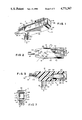
FIG. 3 is a longitudinal sectional view through the plug;
FIG. 4 is a front elevational view of the circuit breaker;
FIG. 5 is a schematic diagram of the electric connections within the plug;
FIG. 6 is an elevational view of two of the plugs mounted in a duplex outlet; and
FIG. 7 is a top plan view of the plug housing only.
DETAILED DESCRIPTION OF THE PREFERRED EMBODIMENT
A safety electric plug constructed in accordance with a preferred aspect of the invention is illustrated in the drawings and generally designated 10. Basically, the plug includes a plug housing or body 12, a prong assembly 14, and a circuit breaker or other over-current protection means 16. The one-piece housing 12 is integrally molded onto the power cord 18 and integrally supports both the prong assembly 14 and the circuit breaker 16. Consequently, the present plug provides integral over-current protection in a compact low-profile assembly.
The housing 12 (FIGS. 1-3 and 7) is preferably injection molded to provide a unitary support mechanism for the remaining components. The housing is elongated including a longitudinal axis 30 and includes opposite relatively narrow top and bottom ends 32 and 34. The bottom end 34 is integrally molded onto the power cord 18 to provide a secure interconnection between the housing and power cord. The cross-sectional configuration of the plug perpendicular to the axis 30 is generally rectangular so that the plug includes a front face 36, a rear face 38, and left and right faces 40 and 42. Gripping ridges 44 and 46 extend the full length of the left and right sides 40 and 42, respectively, to provide a mechanism by which the plug housing can be more easily grasped.
The housing 12 defines a chamber 50 (FIG. 3) which opens through the top end 32. The chamber is generally elongated and oriented generally parallel to the axis 30. As seen in FIG. 7, the chamber 50 is generally square in cross section and extends from the top end 32 to a floor 52 which is approximately midway along the length of the housing 12. A pair of slots 54a and 54b are defined in the floor 52 of the chamber 50 to receive prongs on the circuit breaker as will be described. The perimeter 56 of the opening of the chamber 50 receives the face of the circuit breaker.
The power cord 18 (FIGS. 3 and 5) is generally well known to those having ordinary skill in the art. This is a three-conductor cord including power, common, and ground conductors. The power cord 18 includes an insulating/protective jacket preferably of the same color as the housing 12.
The prong assembly 14 (FIGS. 1-2 and 5) is mounted within the front face 36 at a location proximate the bottom end 34. The prong assembly includes a power prong 60, a power prong (also referred to as a common prong) 62, and a ground prong 64. Preferably, the prongs are fabricated of copper to provide good electric conductivity. The prongs are electrically connected to the conductors within the power cord 18 as will be described. The prongs are sized and arranged to interfit with a conventional receptacle outlet as is well known to those having ordinary skill in the art. The housing 12 is integrally molded about the prongs such that the prongs are integrally and directly supported by the housing. Such structure eliminates the necessity of additional structure for supporting the prong assembly 14. The prongs are generally perpendicular to the axis 30 (see FIG. 3). Further, an imaginary line 70 drawn through the two power prongs 60 and 62 forms an acute angle with the axis 30. Although an angle of approximately forty-five degrees is disclosed, this angle should be substantially nonperpendicular. Preferably, the angle should be in the range zero degrees to approximately forty-five degrees as will be described.
The circuit breaker 16 (FIGS. 3 and 4) are generally well known in the art and are typically referred to as panel breakers since they are most commonly installed within planar control panels. The breaker used in the preferred embodiment is that sold by Mechanical Products, Inc. of Jackson, Mich. as the 2000 Series. The breaker generally includes a body 80 defining a face 82 at one end and integrally supporting prongs 84 at its opposite end. The breaker body is plastic and includes upper and lower spring fingers or other ratchet means 86 which lock the breaker within the chamber 50. The prongs 84 interfit with the slots 542 and 546 in the floor 52 of the chamber 50 to make electric connection with the power conductor in the cord 18 through one slot and the power prong 60 through the other slot. The face 82 fits closely within the perimeter 56 so that the facing 82 is slightly recessed within the housing end 32. As seen in FIG. 1, the breaker further includes a reset button 88 which can be depressed, or pushed in the direction of housing 12, to rest the breaker after it is tripped. The breaker body 80 is generally closely received within the chamber 50. The spring fingers 86 ratchet against the walls of the chamber 50 permitting the breaker to be slid into the chamber 50 during installation but not easily subsequently withdrawn. The breaker capacity will be selected depending on the application. Currently anticipated capacities are in the range 0.25 to 15 amps.
The electric interconnections in the plug are schematically illustrated in FIG. 5. The power cord 18 includes a power conductor 90, a common conductor 92, and a ground conductor 94. The circuit breaker 16 is coupled in series with the power prong 60. Specifically, electric connections, (not specifically shown) are provided in sockets 54a and 54b by which means the circuit breaker 16 is connected with the power conductor 90 and the prong 60. The common conductor 92 is coupled directly to the common prong 62, and the ground conductor 94 is coupled directly to the ground prong 64. All electric connections are made in a manner well-known in the art and are encapsulated within the integrally molded housing 12. The connections are therefore protected from exposure even upon rugged use of the housing.
ASSEMBLY AND OPERATION
Manufacture of the plug is initiated by making all electric connections which will be encapsulated within the plug housing 12. These connections are schematically illustrated in FIG. 5. Specifically, the power conductor 90 is coupled to one socket 54b, and the power prong 60 is coupled to the other socket 54a. The common wire 52 is coupled to the common prong 62; and the ground conductor 94 is coupled to the ground prong 64. The prong assembly 14 is then mounted within a mold insert which holds the prongs in position for subsequent molding. The insert can be rotated through 360 degrees so that the prong assembly 14 can be installed at any desired angular orientation to the housing axis 30.
After all electric connections have been made, the housing 12 is injection molded onto the power cord 18 and the prong assembly 14. During molding, all electric connections are encapsulated within the housing 12.
After the housing cures, the circuit breaker 16 is installed within the chamber 50. As the circuit breaker is slid into the chamber, the prongs 84 slide into slots to establish electric connection with the power conductor 90 and the power prong 60 such that the circuit breaker is coupled in series with the power prong 60. Also as the breaker is slid into position, the fingers 86 engage the chamber walls and are slightly compressed thereby. Breaker insertion continues until the facing 82 extends slightly into perimeter 56. The compressed fingers 86 provide a ratcheting effect to prevent inadvertent removal of the breaker from the housing 12.
The plug can be mounted on any appliance power cord or in conjunction with any device requiring electric power. The plug has its greatest utility in conjunction with appliances which draw large currents such as table saws or other devices with relatively large electric motors. Whenever the appliance or device draws excessive current, the circuit breaker 16 trips to interrupt power to the power prong 60 and consequently to the device powered by the cord. After corrective action has been taken to remedy the over-current situation, the breaker 16 is reset simply by depressing the reset button 88. The plug therefore provides infinitely resettable over-current protection for the appliance.
The desirability of the angular orientation of the prong assembly 14 is illustrated in FIG. 6. Two plugs 10a and 10b are illustrated mounted side-by-side within a conventional duplex outlet 100 including an upper outlet 102, a lower outlet 104, and a cover plate 106. The angular orientation of the prong assemblies (not visible) of the plugs 10a and 10b orients the elongated plug housings 12a and 12b at an angle with respect to the receptacle 100. Consequently the elongated housings 12a and 12b do not overlap or otherwise restrict access to the adjacent outlets. If the angle between the line 70 and the axis 30 (FIG. 2) were 90 degrees, the housings 12a and 12b would undesirably overlie the adjacent receptacle outlets. Conversely, if the line 70 and the axis 30 are parallel, the housings 12a and 12b will be oriented generally horizontally. The optimal range for the angle between the line 70 and the axis 30 is in the range of zero degrees to approximately forty-five degrees to prevent this overlapping problem. In any event, the circuit breakers 16a and 16b of the plugs 10i a and 10b, respectively, are readily accessible for resetting even when the plugs are in the outlets.
The present plug provides a low profile plug with an integral circuit breaker. The low profile enhances safety and the security of the plug within the receptacle. The integral circuit breaker enables power to be easily reestablished without accessing the fuse box or circuit breaker box through which the circuit is connected.
The above description is that of a preferred embodiment of the invention. Various alterations and changes can be made without departing from the spirit and broader aspects of the invention as set forth in the appended claims, which are to be interpreted in accordance with the principles of patent law including the doctrine of equivalents.

Claims (4)

The embodiments of the invention in which an exclusive property or privilege is claimed are defined as follows:
1. An electric plug comprising:
an elongated body having a longitudinal axis and a pair of opposite ends, said body further having a front face between said opposite ends, one of said ends adapted to receive a power cord in a direction generally parallel to said front face; and
a pair of power prongs extending from said front face in a direction generally perpendicular to said body axis, said power prongs being oriented such that a line drawn through said power prongs forms an angle with said body axis, said angle in the range zero degrees to approximately forty-five degrees, whereby said prongs can be inserted into one receptacle of a duplex outlet and said elongated body will not overlie an adjacent receptacle.
2. An electric plug as defined in claim 1 wherein the other of said ends is adapted to receive power-interrupt means in a direction generally parallel to said front face.
3. An electric plug as defined in claim 2 wherein said body defines a chamber opening through the other of said ends, and further wherein said power-interrupt means is slidably received within said chamber and electrically connected in series with one of said prongs, and further wherein said power-interrupt means includes spring-loaded ratchet means for permitting said power-interrupt means to slide into said body and for preventing said power-interrupt means from being removed from said body.
4. An electric plug as defined in claim 1 wherein said body includes a pair of opposite sides, and further comprising a pair of parallel ridges, one on each of said opposite sides of said body and extending outwardly therefrom, said ridges being oriented in the longitudinal direction of the body to facilitate grasping of said body.
US07/046,258 1987-05-04 1987-05-04 Electric plug with circuit breaker Expired - Fee Related US4771367A (en)

Priority Applications (1)

Application Number Priority Date Filing Date Title
US07/046,258 US4771367A (en) 1987-05-04 1987-05-04 Electric plug with circuit breaker

Applications Claiming Priority (1)

Application Number Priority Date Filing Date Title
US07/046,258 US4771367A (en) 1987-05-04 1987-05-04 Electric plug with circuit breaker

Publications (1)

Publication Number Publication Date
US4771367A true US4771367A (en) 1988-09-13

Family

ID=21942486

Family Applications (1)

Application Number Title Priority Date Filing Date
US07/046,258 Expired - Fee Related US4771367A (en) 1987-05-04 1987-05-04 Electric plug with circuit breaker

Country Status (1)

Country Link
US (1) US4771367A (en)

Cited By (22)

* Cited by examiner, † Cited by third party
Publication number Priority date Publication date Assignee Title
US4886462A (en) * 1988-02-01 1989-12-12 Heinemann Electric Company Circuit breaker printed circuit board connector device
US4927376A (en) * 1989-05-17 1990-05-22 Paige Manufacturing Company Incorporated Electrical plug assembly and system
US5252081A (en) * 1992-11-19 1993-10-12 Heron Cable Industries Ltd. Plug for use with self regulating cable
US5399093A (en) * 1994-02-01 1995-03-21 Woods Industries, Inc. Low profile rotatable electrical plug
GB2288697A (en) * 1994-04-22 1995-10-25 Specialised Banking Furniture Plug-in feed module for multi-socket outlet
US5567181A (en) * 1994-03-23 1996-10-22 Woods Industries, Inc. Low profile electrical plug
US5595503A (en) * 1995-06-07 1997-01-21 Woods Industries, Inc. Rotatable electrical plug and power cord
US5600306A (en) * 1994-10-17 1997-02-04 Nisso Industry Co., Ltd. Receptacle unit and extension cord
US5807141A (en) * 1995-06-05 1998-09-15 Sexton; Robert Jay Flat surface-mounted multi-purpose wire
US6350147B2 (en) 1997-11-20 2002-02-26 Superior Modular Products Incorporated High density electrical connector
US6802741B1 (en) 2002-08-22 2004-10-12 Tower Manufacturing Corporation Electric plug for a power cord
US20050190512A1 (en) * 2004-02-26 2005-09-01 Sodemann Wesley C. Electric power system and method of operating the same
US20050231861A1 (en) * 2004-03-25 2005-10-20 Power John J Compact ground fault circuit interrupter module
US7135954B1 (en) 2005-12-24 2006-11-14 Kuoyuh W.L. Enterprise Co., Ltd. Circuit breaker for electric coupling device
US20080261430A1 (en) * 2007-04-20 2008-10-23 Belkin International, Inc. Electrical connector and method of manufacturing same
US20090098743A1 (en) * 2007-04-20 2009-04-16 Belkin International, Inc. Electrical Connector And Method Of Manufacturing Same
US20090145090A1 (en) * 2007-12-07 2009-06-11 Belkin International, Inc. Clamshell Package and Method of Forming Same
US20090225486A1 (en) * 2008-03-07 2009-09-10 Belkin International, Inc. Electrical Connector And Method Of Manufacturing Same
US20090291570A1 (en) * 2008-03-07 2009-11-26 Belkin International, Inc. Electrical Connector And Method Of Manufacturing Same
US20160344182A1 (en) * 2015-05-22 2016-11-24 Twgc Products, Llc Low Profile Surge Protector
US10840654B2 (en) * 2017-04-18 2020-11-17 National Christmas Products Llc Electrical plug for a safety grounded tree
USD955991S1 (en) 2019-07-31 2022-06-28 David M. Solak Electrical outlet safety device

Citations (8)

* Cited by examiner, † Cited by third party
Publication number Priority date Publication date Assignee Title
FR1303127A (en) * 1961-07-27 1962-09-07 Fuse plug
US3873951A (en) * 1973-10-29 1975-03-25 William S Blake Electrical safety device
US4086643A (en) * 1976-04-05 1978-04-25 Jds Products, Inc. Combination plug and power cut-off unit
US4307925A (en) * 1980-02-14 1981-12-29 Noma Canada Ltd. Plug connector with circuit breaker
US4484185A (en) * 1983-08-12 1984-11-20 Graves James D Safety plug adapter
US4488201A (en) * 1983-02-15 1984-12-11 Corcom, Inc. A.C. Power entry module
US4567544A (en) * 1983-10-05 1986-01-28 Pass & Seymour, Inc. Plug-in ground fault circuit interrupter module
US4679884A (en) * 1986-05-07 1987-07-14 Litton Systems, Inc. Fused electrical plug

Patent Citations (8)

* Cited by examiner, † Cited by third party
Publication number Priority date Publication date Assignee Title
FR1303127A (en) * 1961-07-27 1962-09-07 Fuse plug
US3873951A (en) * 1973-10-29 1975-03-25 William S Blake Electrical safety device
US4086643A (en) * 1976-04-05 1978-04-25 Jds Products, Inc. Combination plug and power cut-off unit
US4307925A (en) * 1980-02-14 1981-12-29 Noma Canada Ltd. Plug connector with circuit breaker
US4488201A (en) * 1983-02-15 1984-12-11 Corcom, Inc. A.C. Power entry module
US4484185A (en) * 1983-08-12 1984-11-20 Graves James D Safety plug adapter
US4567544A (en) * 1983-10-05 1986-01-28 Pass & Seymour, Inc. Plug-in ground fault circuit interrupter module
US4679884A (en) * 1986-05-07 1987-07-14 Litton Systems, Inc. Fused electrical plug

Cited By (39)

* Cited by examiner, † Cited by third party
Publication number Priority date Publication date Assignee Title
US4886462A (en) * 1988-02-01 1989-12-12 Heinemann Electric Company Circuit breaker printed circuit board connector device
US4927376A (en) * 1989-05-17 1990-05-22 Paige Manufacturing Company Incorporated Electrical plug assembly and system
WO1990014701A1 (en) * 1989-05-17 1990-11-29 Paige Manufacturing Company Incorporated Electrical plug assembly and system
US5252081A (en) * 1992-11-19 1993-10-12 Heron Cable Industries Ltd. Plug for use with self regulating cable
US5399093A (en) * 1994-02-01 1995-03-21 Woods Industries, Inc. Low profile rotatable electrical plug
WO1995021476A1 (en) * 1994-02-01 1995-08-10 Woods Industries, Inc. Low profile rotatable electrical plug
US5567181A (en) * 1994-03-23 1996-10-22 Woods Industries, Inc. Low profile electrical plug
GB2288697B (en) * 1994-04-22 1997-10-15 Specialised Banking Furniture Electric in-feed module
GB2288697A (en) * 1994-04-22 1995-10-25 Specialised Banking Furniture Plug-in feed module for multi-socket outlet
US5600306A (en) * 1994-10-17 1997-02-04 Nisso Industry Co., Ltd. Receptacle unit and extension cord
US5807141A (en) * 1995-06-05 1998-09-15 Sexton; Robert Jay Flat surface-mounted multi-purpose wire
US5899774A (en) * 1995-06-05 1999-05-04 Sexton; Robert Jay Flat wire connectors for flat surface-mounted multi-purpose wire
US5595503A (en) * 1995-06-07 1997-01-21 Woods Industries, Inc. Rotatable electrical plug and power cord
US6350147B2 (en) 1997-11-20 2002-02-26 Superior Modular Products Incorporated High density electrical connector
US6802741B1 (en) 2002-08-22 2004-10-12 Tower Manufacturing Corporation Electric plug for a power cord
US20050190512A1 (en) * 2004-02-26 2005-09-01 Sodemann Wesley C. Electric power system and method of operating the same
US7104847B2 (en) 2004-02-26 2006-09-12 Briggs & Stratton Power Products Group, Llc Electric power system and method of operating the same
US20060270280A1 (en) * 2004-02-26 2006-11-30 Briggs & Stratton Power Products Group, Llc. Electric power system and method of operating the same
US7390224B2 (en) 2004-02-26 2008-06-24 Briggs & Stratton Corporation Electric power system and method of operating the same
US20050231861A1 (en) * 2004-03-25 2005-10-20 Power John J Compact ground fault circuit interrupter module
US7436639B2 (en) * 2004-03-25 2008-10-14 Power John J Compact ground fault circuit interrupter module
US7135954B1 (en) 2005-12-24 2006-11-14 Kuoyuh W.L. Enterprise Co., Ltd. Circuit breaker for electric coupling device
US7946852B2 (en) 2007-04-20 2011-05-24 Belkin Intenational, Inc. Electrical connector and method of manufacturing same
US20090098743A1 (en) * 2007-04-20 2009-04-16 Belkin International, Inc. Electrical Connector And Method Of Manufacturing Same
US7566223B2 (en) 2007-04-20 2009-07-28 Belkin International, Inc. Electrical connector and method of manufacturing same
US20080261430A1 (en) * 2007-04-20 2008-10-23 Belkin International, Inc. Electrical connector and method of manufacturing same
US20090258508A1 (en) * 2007-04-20 2009-10-15 Belkin International, Inc. Electrical Connector And Method Of Manufacturing Same
US8002554B2 (en) 2007-04-20 2011-08-23 Belkin International, Inc. Electrical connector and method of manufacturing same
US7850458B2 (en) 2007-04-20 2010-12-14 Belkin International, Inc. Electrical connector and method of manufacturing same
US20110065290A1 (en) * 2007-04-20 2011-03-17 Belkin International, Inc. Electrical connector and method of manufacturing same
US20090145090A1 (en) * 2007-12-07 2009-06-11 Belkin International, Inc. Clamshell Package and Method of Forming Same
US20090225486A1 (en) * 2008-03-07 2009-09-10 Belkin International, Inc. Electrical Connector And Method Of Manufacturing Same
US20090291570A1 (en) * 2008-03-07 2009-11-26 Belkin International, Inc. Electrical Connector And Method Of Manufacturing Same
US8197260B2 (en) 2008-03-07 2012-06-12 Belkin International, Inc. Electrical connector and method of manufacturing same
US8469730B2 (en) 2008-03-07 2013-06-25 Belkin International, Inc. Electrical connector and method of manufacturing same
US20160344182A1 (en) * 2015-05-22 2016-11-24 Twgc Products, Llc Low Profile Surge Protector
US10811871B2 (en) * 2015-05-22 2020-10-20 Twgc Products, Llc Low profile surge protector
US10840654B2 (en) * 2017-04-18 2020-11-17 National Christmas Products Llc Electrical plug for a safety grounded tree
USD955991S1 (en) 2019-07-31 2022-06-28 David M. Solak Electrical outlet safety device

Similar Documents

Publication Publication Date Title
US4771367A (en) Electric plug with circuit breaker
US4575704A (en) Electrical adaptor
CA1077163A (en) Portable ground fault circuit interrupting device
CA2095939C (en) Safety construction of receptacle plugs
US4484185A (en) Safety plug adapter
US5930097A (en) Heat responsive power interrupting device cross-reference to related applications
US5562488A (en) Modular outlet assembly
US4767359A (en) Safety electrical wall outlet
CA2051870C (en) Multiple outlet receptacle with circuit breaker and continuity switch mechanisms
US6991495B1 (en) Power strip with self-contained ground fault circuit interrupter module
US3971619A (en) Safe electrical connector
JPH05258788A (en) Combination of terminal lag and connector of breaker
CA2708904C (en) Multiple outlet electrical receptacle
US5848915A (en) Offset power strip
CA2005529C (en) Molded case circuit interrupter rating plug keying and interlock arrangement
CA1036682A (en) Dual-standard electric plug
US2289122A (en) Electric circuit controlling device
US4928080A (en) Molded case circuit breaker line terminal plug
US2524250A (en) Electrical outlet safety accessory
US6759939B2 (en) Fuse holder assembly
US2974301A (en) Duplex plug receptacle
GB1576607A (en) In-line multi-socket outlet unit
KR100608145B1 (en) power saving socket and power saving multi-socket
JP3248319U (en) Overload protection device for multi-national power converters
US3154722A (en) Fusible circuit protective device

Legal Events

Date Code Title Description
AS Assignment

Owner name: HIGH Q MANUFACTURING CO., NINE INFINITY LANE, P.O.

Free format text: ASSIGNMENT OF ASSIGNORS INTEREST.;ASSIGNORS:SERR, MICHAEL J.;SERR, CARLYLE;PIERCE, LAWRENCE E.;REEL/FRAME:004743/0172

Effective date: 19870623

Owner name: HIGH Q MANUFACTURING CO., A CORP. OF MI,MICHIGAN

Free format text: ASSIGNMENT OF ASSIGNORS INTEREST;ASSIGNORS:SERR, MICHAEL J.;SERR, CARLYLE;PIERCE, LAWRENCE E.;REEL/FRAME:004743/0172

Effective date: 19870623

FEPP Fee payment procedure

Free format text: PAYOR NUMBER ASSIGNED (ORIGINAL EVENT CODE: ASPN); ENTITY STATUS OF PATENT OWNER: LARGE ENTITY

REMI Maintenance fee reminder mailed
LAPS Lapse for failure to pay maintenance fees
FP Lapsed due to failure to pay maintenance fee

Effective date: 19920913

FP Lapsed due to failure to pay maintenance fee

Effective date: 19920913

STCH Information on status: patent discontinuation

Free format text: PATENT EXPIRED DUE TO NONPAYMENT OF MAINTENANCE FEES UNDER 37 CFR 1.362