US4756190A - Direct-heated flow measuring apparatus having uniform characteristics - Google Patents
Direct-heated flow measuring apparatus having uniform characteristics Download PDFInfo
- Publication number
- US4756190A US4756190A US06/894,895 US89489586A US4756190A US 4756190 A US4756190 A US 4756190A US 89489586 A US89489586 A US 89489586A US 4756190 A US4756190 A US 4756190A
- Authority
- US
- United States
- Prior art keywords
- set forth
- thermal conductivity
- film resistor
- thermally insulating
- conductivity coefficient
- Prior art date
- Legal status (The legal status is an assumption and is not a legal conclusion. Google has not performed a legal analysis and makes no representation as to the accuracy of the status listed.)
- Expired - Lifetime
Links
- 239000000853 adhesive Substances 0.000 claims abstract description 22
- 230000001070 adhesive effect Effects 0.000 claims abstract description 22
- 239000000758 substrate Substances 0.000 claims abstract description 22
- 229920005989 resin Polymers 0.000 claims description 6
- 239000011347 resin Substances 0.000 claims description 6
- 238000007772 electroless plating Methods 0.000 claims description 5
- 229910015365 Au—Si Inorganic materials 0.000 claims description 4
- 229910021421 monocrystalline silicon Inorganic materials 0.000 claims description 4
- 229910020220 Pb—Sn Inorganic materials 0.000 claims description 3
- 229910052782 aluminium Inorganic materials 0.000 claims description 3
- KZHJGOXRZJKJNY-UHFFFAOYSA-N dioxosilane;oxo(oxoalumanyloxy)alumane Chemical compound O=[Si]=O.O=[Si]=O.O=[Al]O[Al]=O.O=[Al]O[Al]=O.O=[Al]O[Al]=O KZHJGOXRZJKJNY-UHFFFAOYSA-N 0.000 claims description 3
- 239000006023 eutectic alloy Substances 0.000 claims description 3
- 239000011521 glass Substances 0.000 claims description 3
- 229910052863 mullite Inorganic materials 0.000 claims description 3
- 229920001721 polyimide Polymers 0.000 claims description 3
- 229910000679 solder Inorganic materials 0.000 claims description 3
- 239000004411 aluminium Substances 0.000 claims description 2
- XAGFODPZIPBFFR-UHFFFAOYSA-N aluminium Chemical compound [Al] XAGFODPZIPBFFR-UHFFFAOYSA-N 0.000 claims description 2
- 239000000919 ceramic Substances 0.000 claims description 2
- 229910052802 copper Inorganic materials 0.000 claims description 2
- RYGMFSIKBFXOCR-UHFFFAOYSA-N Copper Chemical compound [Cu] RYGMFSIKBFXOCR-UHFFFAOYSA-N 0.000 claims 1
- 239000010949 copper Substances 0.000 claims 1
- 230000000694 effects Effects 0.000 abstract description 11
- 230000002708 enhancing effect Effects 0.000 abstract description 2
- 239000003570 air Substances 0.000 description 37
- 230000001419 dependent effect Effects 0.000 description 26
- BASFCYQUMIYNBI-UHFFFAOYSA-N platinum Chemical compound [Pt] BASFCYQUMIYNBI-UHFFFAOYSA-N 0.000 description 12
- 230000004048 modification Effects 0.000 description 10
- 238000012986 modification Methods 0.000 description 10
- 238000010438 heat treatment Methods 0.000 description 7
- 239000010931 gold Substances 0.000 description 6
- 230000001965 increasing effect Effects 0.000 description 6
- VYPSYNLAJGMNEJ-UHFFFAOYSA-N Silicium dioxide Chemical compound O=[Si]=O VYPSYNLAJGMNEJ-UHFFFAOYSA-N 0.000 description 4
- 230000003247 decreasing effect Effects 0.000 description 4
- 238000004519 manufacturing process Methods 0.000 description 4
- 229910052697 platinum Inorganic materials 0.000 description 4
- 238000002485 combustion reaction Methods 0.000 description 3
- 238000011144 upstream manufacturing Methods 0.000 description 3
- 229910052681 coesite Inorganic materials 0.000 description 2
- 239000004020 conductor Substances 0.000 description 2
- 229910052906 cristobalite Inorganic materials 0.000 description 2
- 230000007423 decrease Effects 0.000 description 2
- 238000010586 diagram Methods 0.000 description 2
- 239000000446 fuel Substances 0.000 description 2
- 229910052737 gold Inorganic materials 0.000 description 2
- 230000017525 heat dissipation Effects 0.000 description 2
- 238000002347 injection Methods 0.000 description 2
- 239000007924 injection Substances 0.000 description 2
- 238000002161 passivation Methods 0.000 description 2
- 239000000377 silicon dioxide Substances 0.000 description 2
- 229910052682 stishovite Inorganic materials 0.000 description 2
- 229910052905 tridymite Inorganic materials 0.000 description 2
- 229910007277 Si3 N4 Inorganic materials 0.000 description 1
- 239000012080 ambient air Substances 0.000 description 1
- 229910010293 ceramic material Inorganic materials 0.000 description 1
- 239000002826 coolant Substances 0.000 description 1
- 230000003628 erosive effect Effects 0.000 description 1
- 230000005496 eutectics Effects 0.000 description 1
- PCHJSUWPFVWCPO-UHFFFAOYSA-N gold Chemical compound [Au] PCHJSUWPFVWCPO-UHFFFAOYSA-N 0.000 description 1
- 229920006015 heat resistant resin Polymers 0.000 description 1
- 239000007788 liquid Substances 0.000 description 1
- 239000000463 material Substances 0.000 description 1
- PXHVJJICTQNCMI-UHFFFAOYSA-N nickel Substances [Ni] PXHVJJICTQNCMI-UHFFFAOYSA-N 0.000 description 1
Images


Classifications
-
- G—PHYSICS
- G01—MEASURING; TESTING
- G01F—MEASURING VOLUME, VOLUME FLOW, MASS FLOW OR LIQUID LEVEL; METERING BY VOLUME
- G01F1/00—Measuring the volume flow or mass flow of fluid or fluent solid material wherein the fluid passes through a meter in a continuous flow
- G01F1/68—Measuring the volume flow or mass flow of fluid or fluent solid material wherein the fluid passes through a meter in a continuous flow by using thermal effects
- G01F1/684—Structural arrangements; Mounting of elements, e.g. in relation to fluid flow
- G01F1/688—Structural arrangements; Mounting of elements, e.g. in relation to fluid flow using a particular type of heating, cooling or sensing element
- G01F1/69—Structural arrangements; Mounting of elements, e.g. in relation to fluid flow using a particular type of heating, cooling or sensing element of resistive type
- G01F1/692—Thin-film arrangements
Definitions
- the present invention relates to a direct-heated flow measuring apparatus having a film resistor which serves as a temperature detecting means as well as an electric heater.
- a direct-heated flow measuring apparatus can be used, for example, for measuring the flow rate of engine intake air.
- the amount of intake air is one of the most important parameters for controlling the fuel injection amount, ignition timing, and the like.
- a flow measuring apparatus i.e., an airflow meter
- An airflow meter is provided for measuring the same.
- One of the more common prior art airflow meters is the vane-type, but this is disadvantageous in scale, response speed characteristics, and the like, and therefore, airflow meters having temperature-dependent resistors have been developed, in which these disadvantages of scale, response speed characteristics, and the like are avoided (see: U.S. Pat. No. 3,975,951).
- the heater-type airflow meter may consist of an electric heater resistor provided in an intake-air passage of an engine and two temperature-dependent resistors arranged on the upstream and downstream sides of the electric heater resistor.
- the temperature-dependent resistor on the downstream side is used for detecting the temperature of air heated by the heater resistor
- the temperature-dependent resistor on the upstream side is used for detecting the temperature of non-heated air.
- the current flowing through the heater resistor is controlled to provide a constant difference in temperature between the two temperature-dependent resistors, and thus the mass flow rate of air is determined by detecting the voltage applied to the heater resistor.
- the direct-heated type airflow meter may consist of a film resistor which serves not only as an electric heater, but also as a temperature-detecting means for detecting the temperature of the heated air.
- the direct-heated type airflow meter may consist of a temperature-dependent resistor for detecting the temperature of non-heated air.
- the direct-heated type airflow meter serves as a temperature-detecting means for heated air, that is, an additional temperature detecting means for heated air is not necessary, the direct-heated type airflow meter is smaller in size than the heater-type airflow meter.
- the film resistor may consist of an insulating substrate such as a ceramic substrate or monocrystalline silicon substrate, a resistance pattern layer of platinum (Pt), gold (Au), etc. on the insulating substrate, and a heat-resistant resin or a passivation layer on the resistance pattern layer.
- the response characteristics and dynamic range of the direct-heated type airflow meter are dependent upon the heat mass and adiabatic efficiency of the heating and temperature detecting portion of the resistance pattern layer, which serves not only as a heating means but also as a temperature detecting means.
- the above-mentioned portion should be ideally in a completely floating state in the air stream.
- a direct-heated airflow meter in which the substrate is fixed by an adiabatic member to a supporting member having good heat dissipation characteristics.
- the adhesion between the substrate and the adiabatic member and the adhesion between the adiabatic member and the supporting member are carried out by using adhesives having an adiabatic effect, thus further enhancing the adiabatic effect of the heater and temperature detecting portion.
- adhesives are, for example, resin adhesives, frit glass, and the like.
- the thickness state, and the like of the above-mentioned adhesives fluctuate according to the manufacturing conditions thereof, and accordingly, the adiabatic effect thereof is fluctuated.
- fluctuations occur in the response characteristics and dynamic range of the airflow meter.
- the substrate is adhered by adhesives having an excellent thermal conductivity coefficient to the adiabatic member
- the supporting member is also adhered by adhesives having an excellent thermal conductivity coefficient to the adiabatic member.
- FIG. 1 is a schematic diagram showing the overall configuration of an internal combustion engine including an embodiment of the direct-heated flow measuring apparatus according to the present invention
- FIG. 2 is a circuit diagram of the sensor circuit of FIG. 1;
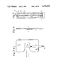
- FIG. 3 is a plan view of the film resistor and the supporting member of FIG. 1;
- FIG. 4 is a cross-sectional view taken along the line IV--IV of FIG. 3;
- FIG. 5 is an enlargement of the film resistor of FIG. 3;
- FIG. 6 is a cross-sectional view of the adiabatic member of FIG. 4;
- FIG. 7 is a modification of the adiabatic member of FIG. 6;
- FIG. 8 is a graph showing the thermal conductivity characteristics of the adiabatic member of FIG. 7;
- FIG. 9 is a plan view of the flexible connection of FIG. 1;
- FIG. 10 is a cross-sectional view taken along the line X--X of FIG. 9;
- FIG. 11 is another modification of the adiabatic member of FIG. 6;
- FIG. 12 is a modification of the film resistor and the supporting member of FIG. 3;
- FIG. 13 is a still another modification of the adiabatic member of FIG. 6;
- FIG. 14 is another modification of the film resistor and the supporting member of FIG. 3;
- FIG. 15 is a cross-sectional view taken along the line XV--XV of FIG. 14;
- FIG. 16 is an enlargement of the film resistor of FIG. 14;
- FIG. 17A is a still another modification of the film resistor and the supporting member of FIG. 1;
- FIG. 17B is a cross-sectional view taken along the line B--B of FIG. 17A.
- reference numeral 1 designates a spark ignition engine for driving an automobile in which air for combustion is sucked through an air cleaner 2, a rectifier grid 3 for making the air flow uniform, and an intake air passage 4.
- a throttle valve 4a arbitrarily operated by a driver.
- the flow measuring apparatus is provided in the intake air passage 4 between the rectifier grid 3 and the throttle valve 4a.
- the flow measuring apparatus includes a sensing portion inside of the intake air passage 4 and a sensor circuit 10 encapsulated in a hybrid board outside of the intake air passage 4.
- the sensing portion includes a supporting member 5 (such as aluminium) which supports a temperature-dependent resistor (film resistor ) 6 in the intake air passage 4.
- the film resistor 6, which includes a heating and temperature-detecting portion, is connected via a flexible connection 7 to the sensor circuit 10.
- the supporting member 5 also supports a temperature-dependent resistor 8 for detecting the temperature of non-heated air in the intake air passage 4.
- the temperature-dependent resistor 8 is connected via a flexible connection 9 to the sensor circuit 10. Note that the temperature-dependent resistor 8 is disposed within the intake air passage 4 in such a way that the resistor 8 is not substantially affected by the heat generated from the film resistor 6, and there is no substantial fluctuation of the air stream against the film resistor 6.
- the sensor circuit 10 controls the current flowing to the film resistor 6 to generate heat to provide a constant difference in temperature between the film resistor 6 and the temperature-dependent resistor 8. Also, the sensor circuit 10 generates and transmits an output voltage V Q to the control circuit 11, which includes, for example, a microcomputer.
- the control circuit 11 also receives various kinds of detecting signals such as an engine speed signal Ne (not shown) and an engine coolant temperature signal THW (not shown) and controls the valve opening time period of a fuel injection valve 12 and the like.
- the sensor circuit 10 of FIG. 1 will be explained with reference to FIG. 2.
- the sensor circuit 10 includes resistors 101 and 102 which form a bridge circuit with the film resistor 6 and the temperature-dependent resistor 8; a comparator 103; a transistor 104 controlled by the comparator 103; and a voltage buffer 105.
- the sensor circuit 10 operates as follows. When the amount of air flowing through the intake air passage 4 increases, thus reducing the temperature of the film resistor 6, which is, in this case, a platinum resistor, the resistance value thereof decreases so as to satisfy the following condition:
- V 1 is the potential at the node between the resistor 101 and the film resistor 6 and V R is the potential at the node between the resistor 102 and the temperature-dependent resistor 8.
- V R is the potential at the node between the resistor 102 and the temperature-dependent resistor 8.
- the output potential of the comparator 103 is increased, thereby decreasing the conductivity of the transistor 104. Therefore, the heat generated by the film resistor 6 is decreased and, simultaneously, the collector potential of the transistor 104 is decreased, so that the output voltage V Q of the voltage buffer 105 is also decreased.
- the output voltage V Q of the output buffer 105 indicates the amount of air flowing through the intake air passage 4.
- FIG. 3 is an enlargement of FIG. 1 in the periphery of the film resistor 6, and FIG. 4 is a cross-sectional view taken along the line IV--IV. Note that the temperature-dependent resistor 8 and the flexible connector 9 are omitted from FIG. 3. As illustrated in FIGS. 3 and 4, only one end of the film resistor 6 is supported by an adiabatic member 13 in the supporting member 5, so that the face thereof having a resistance pattern thereon is parallel to the air stream, i.e., the minimum dimension portion of the film resistor 6 is opposed to the air stream.
- FIG. 5 is an enlargement of the film resistor 6 of FIG. 3.
- the film resistor 6 comprises a monocrystalline silicon substrate 61 and a platinum (Pt) resistance pattern layer 62.
- the passivation layer SiO 2 or Si 3 N 4 ) (not shown) is provided for protecting the Pt resistance pattern layer 62.
- the SiO 2 layer obtained by thermally-oxidizing the substrate 61 is provided between the substrate 61 and the Pt resistance pattern layer 62.
- the portion 62a thereof having a particularly large resistance value serves not only as a heater by receiving a power supply, but also as a temperature-detecting portion by detecting a resistance value thereof.
- P 1 and P 2 are lead take-out portions.
- FIG. 6 is a cross-sectional view of the periphery of the adiabatic member 13 of FIG. 4.
- the first adhesive member 14 may consist of an Au printing layer 14-1 and an Au-Si eutectic alloy layer 14-2. That is, the Au printing layer 14-1 is formed on the face of the adiabatic member 13 in advance, and then the adiabatic member 13 is pressed onto the substrate 61 at an appropriate pressure and at a temperature of about 400° C. Thus, the Au-Si eutectic layer 14-2 is produced between the Au printing layer 14-1 and the substrate 61, so that the adiabatic member 13 is adhered to the substrate 61.
- the second adhesive member 15 may consist of an electroless plating layer 15-1 and a Pb-Sn solder layer 15-2. That is, the electroless plating layer 15-1 is formed on the face of the adiabatic member 13 in advance, and then the Pb-Sn solder layer 15-2 is formed between the electroless plating layer 15-1 and the supporting member 5, so that the adiabatic member 13 is adhered to the supporting member 5.
- the adiabatic effect for the film resistor 6 is dependent only upon the adiabatic member 13. Therefore, even when the thickness, state, and the like of the adhesive members 14 and 15 are fluctuated, the adiabatic effect for the film resistor 6 is not fluctuated.
- the adiabatic member 13 consists of an adiabatic member 13-1 such as mullite having a negative thermal conductivity coefficient, as shown in FIG. 8, and an adiabatic member 13-2 such as polyimid having a positive thermal conductivity coefficient, as also shown in FIG. 8.
- the adiabatic members 13-1 and 13-2 are adhered to each other by heat-resistant adhesives 13-3.
- the thickness of the negative adiabatic member 13-1 and the thickness of the positive adiabatic member 13-2 are adjusted in such a way that the negative thermal conductivity characteristics of the adiabatic member are counteracted by the positive thermal conductivity characteristics of the adiabatic member 13-2.
- the thermal conductivity coefficient of the entire adiabatic member 13 can be uniform regardless of the temperature.
- the heat dissipation characteristics of the adiabatic member 13 do not change, thus reducing any change of the sensor output V Q due to the change of the temperature.
- the negative thermal conductivity coefficient adiabatic member 13-1 ceramic material, glass material, and the like can be used instead of mullite.
- other resins can be used instead of polyimid.
- the adiabatic members 13-1 and 13-2 are laminated in FIG. 7, the adiabatic members 13-1 and 13-2 can be mixed.
- FIG. 9 is an enlargement of the flexible connection 7 of FIG. 1, and FIG. 10 is a cross-sectional view taken along the line X--X of FIG. 9.
- the flexible connection 7 is comprised of a flexible insulating resin film 701, conductors (such as Cu) 702a and 702b, and a flexible insulating resin film 703. That is, the conductors 702a and 702b are sandwiched by the flexible insulating resin films 701 and 703. Connection portions A and B are connected to the lead take-out portions P 1 and P 2 of FIG. 5 by Au-Si eutectic alloy.
- the flexible connection 7 has a structure resistant to erosion, disconnection, and the like, as compared with bonding wires.
- FIG. 11 which is another modification of FIG. 6, the entire adiabatic member 13 is covered by a conductive layer 16 made of electroless plating Au, Pt, or Ni. Since the adhesive members 14 and 15 are also conductive the lead take-out portions P 1 and P 2 of the resistance layer 62 (see FIG. 5) are electrically connected to conductive layers 18a and 18b (see FIG. 12) on the supporting member 5. In this case, the adiabatic member 13 is provided for each of the lead take-out portions P 1 and P 2 . Note that reference numeral 19 of FIG. 12 indicates an insulating layer for insulating the conductive layers 18a and 18b from the supporting member 5.
- the resistance layer 62 of the film resistor 6 is connected to the conductive layers 18a and 18b via the conductive layer 16 formed on the adiabatic member 13, and thus the flexible connection 7 is not required.
- FIG. 13 which is a further modification of FIG. 6 (FIG. 11)
- conductive plates 17a and 17b are formed on both faces of the adiabatic member 13, and a conductive rod 17c is provided at the center of the adiabatic member 13.
- the conductive plates 17a and 17b are electrically connected by the conductive rod 17c. Therefore, the structure of FIG. 13 can be used instead of FIG. 11.
- the structure as illustrated in FIGS. 11(13) and 12 can be applied to a structure in which both ends of the film resistor 6 are fixed to the supporting member 5. That is, as illustrated in FIGS. 14 and 15, conductive layers 20a and 20b are formed via insulating layers 21a and 21b on the supporting members 5. The ends of the film resistor 6 as illustrated in FIG. 16 are fixed by the two adiabatic members 13 covered by the conductive layers 16 to the conductive layers 20a and 20b.
- FIG. 17A is a modification of FIG. 14, and FIG. 17B is a cross-sectional view taken along the line B--B of FIG. 17A.
- the conductive layers 20a and 20b, and the insulating layers 21a and 21b of FIG. 14 are not provided, but instead, two conductive supporting members 5a and 5b are separated from each other, and are supported by an insulating supporting member 22.
- the ends of the film resistor 6 are connected electrically to the conductive supporting members 5a and 5b, respectively.
- the present invention can be applied to flow rate sensors other than airflow rate sensors, such as liquid flow rate sensors. Further, the present invention can be applied to a digital (pulse) type flow rate sensor controlled by a trigger pulse. That is, in this sensor, when such a trigger pulse is given to initiate heating of a heater resistor, then the heating of the heater resistor continues until a constant difference in temperature between two temperature-dependent resistors is generated, or until the downstream temperature-dependent resistor reaches a constant value. In this case, the heating time period is detected as the mass flow rate of air or the volume flow rate of air.
- a trigger pulse control has an advantage in that the power dissipation is good. Note that such a trigger pulse control is possible in a direct-heated flow rate sensor.
- the adhesive member between the film resistor and the adiabatic member, and the adhesive member between the adiabatic member and the supporting member are conductive, the adiabatic effect is dependent upon only the adiabatic member. Thus, the response characteristics and dynamic range of the sensor are not fluctuated by the manufacturing conditions thereof.
Abstract
Description
V.sub.1 ≦V.sub.R
V.sub.1 >V.sub.R.
Claims (15)
Applications Claiming Priority (6)
| Application Number | Priority Date | Filing Date | Title |
|---|---|---|---|
| JP60174341A JPS6235225A (en) | 1985-08-09 | 1985-08-09 | Direct heat type flow rate sensor |
| JP60-174341 | 1985-08-09 | ||
| JP60175652A JPS6236521A (en) | 1985-08-12 | 1985-08-12 | Direct-heating type flow-rate sensor |
| JP60-175652 | 1985-08-12 | ||
| JP60-178522 | 1985-08-15 | ||
| JP60178522A JPS6239720A (en) | 1985-08-15 | 1985-08-15 | Direct heating type flow sensor |
Publications (1)
| Publication Number | Publication Date |
|---|---|
| US4756190A true US4756190A (en) | 1988-07-12 |
Family
ID=27323926
Family Applications (1)
| Application Number | Title | Priority Date | Filing Date |
|---|---|---|---|
| US06/894,895 Expired - Lifetime US4756190A (en) | 1985-08-09 | 1986-08-08 | Direct-heated flow measuring apparatus having uniform characteristics |
Country Status (1)
| Country | Link |
|---|---|
| US (1) | US4756190A (en) |
Cited By (6)
| Publication number | Priority date | Publication date | Assignee | Title |
|---|---|---|---|---|
| EP0528251A2 (en) * | 1991-08-21 | 1993-02-24 | Honda Giken Kogyo Kabushiki Kaisha | Method of making a semiconductor type gas flow sensor |
| US5201221A (en) * | 1991-03-15 | 1993-04-13 | Ford Motor Company | Flow sensor and method of manufacture |
| US5723784A (en) * | 1995-07-06 | 1998-03-03 | Robert Bosch Gmbh | Flow rate meter |
| US5993892A (en) * | 1996-09-12 | 1999-11-30 | Wasserman; Arthur | Method of monitoring and controlling electroless plating in real time |
| US20030233886A1 (en) * | 2002-06-21 | 2003-12-25 | Mitsubishi Denki Kabushiki Kaisha | Flow rate sensor |
| US20100162809A1 (en) * | 2007-05-10 | 2010-07-01 | Acque Ingegneria S.R.L. | Flow rate sensor for water ducts and a method for measuring water flow |
Citations (6)
| Publication number | Priority date | Publication date | Assignee | Title |
|---|---|---|---|---|
| US3747577A (en) * | 1970-08-29 | 1973-07-24 | Bosch Gmbh Robert | Temperature-dependent resistance arrangement for controlling fuel injection as a function of air intake |
| US3975951A (en) * | 1974-03-21 | 1976-08-24 | Nippon Soken, Inc. | Intake-air amount detecting system for an internal combustion engine |
| US4279146A (en) * | 1978-10-03 | 1981-07-21 | Robert Bosch Gmbh | Apparatus for measuring the air quantity supplied to an internal combustion engine |
| US4513615A (en) * | 1982-12-08 | 1985-04-30 | Hitachi, Ltd. | Thermal air flow meter |
| US4559814A (en) * | 1983-03-07 | 1985-12-24 | Hitachi, Ltd. | Thermal air flow meter |
| US4627279A (en) * | 1984-05-09 | 1986-12-09 | Nippon Soken, Inc. | Direct-heated gas-flow measuring apparatus |
-
1986
- 1986-08-08 US US06/894,895 patent/US4756190A/en not_active Expired - Lifetime
Patent Citations (6)
| Publication number | Priority date | Publication date | Assignee | Title |
|---|---|---|---|---|
| US3747577A (en) * | 1970-08-29 | 1973-07-24 | Bosch Gmbh Robert | Temperature-dependent resistance arrangement for controlling fuel injection as a function of air intake |
| US3975951A (en) * | 1974-03-21 | 1976-08-24 | Nippon Soken, Inc. | Intake-air amount detecting system for an internal combustion engine |
| US4279146A (en) * | 1978-10-03 | 1981-07-21 | Robert Bosch Gmbh | Apparatus for measuring the air quantity supplied to an internal combustion engine |
| US4513615A (en) * | 1982-12-08 | 1985-04-30 | Hitachi, Ltd. | Thermal air flow meter |
| US4559814A (en) * | 1983-03-07 | 1985-12-24 | Hitachi, Ltd. | Thermal air flow meter |
| US4627279A (en) * | 1984-05-09 | 1986-12-09 | Nippon Soken, Inc. | Direct-heated gas-flow measuring apparatus |
Cited By (8)
| Publication number | Priority date | Publication date | Assignee | Title |
|---|---|---|---|---|
| US5201221A (en) * | 1991-03-15 | 1993-04-13 | Ford Motor Company | Flow sensor and method of manufacture |
| EP0528251A2 (en) * | 1991-08-21 | 1993-02-24 | Honda Giken Kogyo Kabushiki Kaisha | Method of making a semiconductor type gas flow sensor |
| EP0528251A3 (en) * | 1991-08-21 | 1994-07-06 | Honda Motor Co Ltd | Semiconductor type gas flow sensor |
| US5723784A (en) * | 1995-07-06 | 1998-03-03 | Robert Bosch Gmbh | Flow rate meter |
| US5993892A (en) * | 1996-09-12 | 1999-11-30 | Wasserman; Arthur | Method of monitoring and controlling electroless plating in real time |
| US20030233886A1 (en) * | 2002-06-21 | 2003-12-25 | Mitsubishi Denki Kabushiki Kaisha | Flow rate sensor |
| US6789418B2 (en) * | 2002-06-21 | 2004-09-14 | Mitsubishi Denki Kabushiki Kaisha | Flow rate sensor |
| US20100162809A1 (en) * | 2007-05-10 | 2010-07-01 | Acque Ingegneria S.R.L. | Flow rate sensor for water ducts and a method for measuring water flow |
Similar Documents
| Publication | Publication Date | Title |
|---|---|---|
| US4870860A (en) | Direct-heated flow measuring apparatus having improved response characteristics | |
| US4843882A (en) | Direct-heated flow measuring apparatus having improved sensitivity response speed | |
| JP3583773B2 (en) | Thermal air flow meter | |
| US4677850A (en) | Semiconductor-type flow rate detecting apparatus | |
| US4833912A (en) | Flow measuring apparatus | |
| US6889545B2 (en) | Flow rate sensor | |
| US5351536A (en) | Air flow rate detector | |
| US4627279A (en) | Direct-heated gas-flow measuring apparatus | |
| JPS60151517A (en) | Semiconductor type flow rate detector | |
| US4587843A (en) | Thermocouple-type gas-flow measuring apparatus | |
| US4756190A (en) | Direct-heated flow measuring apparatus having uniform characteristics | |
| JPH0422208B2 (en) | ||
| US6684693B2 (en) | Heat generation type flow sensor | |
| JP3331814B2 (en) | Thermal flow detector | |
| GB2171800A (en) | Mounting heated-resistor fluid-flow measuring sensors | |
| US4761995A (en) | Direct-heated flow measuring apparatus having improved sensitivity and response speed | |
| US4770036A (en) | Apparatus for measuring velocity of flow | |
| JP2784192B2 (en) | Hot film type air flow meter | |
| JPS62147319A (en) | Direct heating type flow sensor | |
| JPS5895265A (en) | Thermal type flow meter | |
| JPH0441932B2 (en) | ||
| JP2842485B2 (en) | Thermal flow sensor | |
| JP2633994B2 (en) | Thermal air flow meter | |
| JPS6236521A (en) | Direct-heating type flow-rate sensor | |
| JPH0330090B2 (en) |
Legal Events
| Date | Code | Title | Description |
|---|---|---|---|
| AS | Assignment |
Owner name: NIPPON SOKEN, INC., 14, IWAYA, SHIMOHASUMI-CHO, NI Free format text: ASSIGNMENT OF ASSIGNORS INTEREST.;ASSIGNORS:OHTA, MINORU;ONODA, MICHITOSHI;MIURA, KAZUHIKO;AND OTHERS;REEL/FRAME:004606/0228 Effective date: 19860728 Owner name: NIPPON SOKEN, INC., 14, IWAYA, SHIMOHASUMI-CHO, NI Free format text: ASSIGNMENT OF ASSIGNORS INTEREST;ASSIGNORS:OHTA, MINORU;ONODA, MICHITOSHI;MIURA, KAZUHIKO;AND OTHERS;REEL/FRAME:004606/0228 Effective date: 19860728 |
|
| STCF | Information on status: patent grant |
Free format text: PATENTED CASE |
|
| FEPP | Fee payment procedure |
Free format text: PAYOR NUMBER ASSIGNED (ORIGINAL EVENT CODE: ASPN); ENTITY STATUS OF PATENT OWNER: LARGE ENTITY |
|
| FPAY | Fee payment |
Year of fee payment: 4 |
|
| REMI | Maintenance fee reminder mailed | ||
| FPAY | Fee payment |
Year of fee payment: 8 |
|
| FPAY | Fee payment |
Year of fee payment: 12 |