US4744644A - Membrane concentrator mirror - Google Patents
Membrane concentrator mirror Download PDFInfo
- Publication number
- US4744644A US4744644A US06/930,795 US93079586A US4744644A US 4744644 A US4744644 A US 4744644A US 93079586 A US93079586 A US 93079586A US 4744644 A US4744644 A US 4744644A
- Authority
- US
- United States
- Prior art keywords
- membrane
- segments
- concentrator mirror
- clamping
- mirror according
- Prior art date
- Legal status (The legal status is an assumption and is not a legal conclusion. Google has not performed a legal analysis and makes no representation as to the accuracy of the status listed.)
- Expired - Fee Related
Links
- 239000012528 membrane Substances 0.000 title claims abstract description 61
- XAGFODPZIPBFFR-UHFFFAOYSA-N aluminium Chemical compound [Al] XAGFODPZIPBFFR-UHFFFAOYSA-N 0.000 claims description 5
- 229910052782 aluminium Inorganic materials 0.000 claims description 5
- 239000002390 adhesive tape Substances 0.000 claims description 3
- 239000006260 foam Substances 0.000 claims description 3
- 239000011888 foil Substances 0.000 claims description 3
- 229920000642 polymer Polymers 0.000 claims description 2
- 239000004332 silver Substances 0.000 claims description 2
- 229910052709 silver Inorganic materials 0.000 claims description 2
- 230000003287 optical effect Effects 0.000 abstract description 4
- 230000000694 effects Effects 0.000 abstract 1
- 238000010276 construction Methods 0.000 description 5
- 239000004411 aluminium Substances 0.000 description 3
- 239000000853 adhesive Substances 0.000 description 1
- 230000001070 adhesive effect Effects 0.000 description 1
Images


Classifications
-
- F—MECHANICAL ENGINEERING; LIGHTING; HEATING; WEAPONS; BLASTING
- F24—HEATING; RANGES; VENTILATING
- F24S—SOLAR HEAT COLLECTORS; SOLAR HEAT SYSTEMS
- F24S23/00—Arrangements for concentrating solar-rays for solar heat collectors
- F24S23/70—Arrangements for concentrating solar-rays for solar heat collectors with reflectors
- F24S23/71—Arrangements for concentrating solar-rays for solar heat collectors with reflectors with parabolic reflective surfaces
- F24S23/715—Arrangements for concentrating solar-rays for solar heat collectors with reflectors with parabolic reflective surfaces flexible
-
- Y—GENERAL TAGGING OF NEW TECHNOLOGICAL DEVELOPMENTS; GENERAL TAGGING OF CROSS-SECTIONAL TECHNOLOGIES SPANNING OVER SEVERAL SECTIONS OF THE IPC; TECHNICAL SUBJECTS COVERED BY FORMER USPC CROSS-REFERENCE ART COLLECTIONS [XRACs] AND DIGESTS
- Y02—TECHNOLOGIES OR APPLICATIONS FOR MITIGATION OR ADAPTATION AGAINST CLIMATE CHANGE
- Y02E—REDUCTION OF GREENHOUSE GAS [GHG] EMISSIONS, RELATED TO ENERGY GENERATION, TRANSMISSION OR DISTRIBUTION
- Y02E10/00—Energy generation through renewable energy sources
- Y02E10/40—Solar thermal energy, e.g. solar towers
Definitions
- the invention relates to a membrane concentrator mirror with a frame-like basic body, with a membrane stretched over the basic body.
- Membrane parabolic dish mirrors which are formed by the pneumatic, hydraulic, electric, magnetic or electromagnetic deformation of originally plane membranes or individual membrane sections offer the basic advantage of low weight and easy construction as compared to conventional concentrator mirrors. These advantages are especially relevant in the case of the use of such concentrator mirrors for the concentration of sun energy.
- Such a membrane concentrator mirror is known from U.S. Pat. No. 4,033,676, the membrane comprising a plurlaity of membrane sections.
- the membrane is exclusively secured along a circular outer rim of the basic body, so that the resulting mirror configuration corresponds exclusively to the equilibrium status of membrane stress and internal sub-pressure, and air-pressure of the surrounding air, respectively.
- the several membrane segments are connected with one another in such a way that rigid, radially extending clamping profiles clampingly secure the radially extending outer rims by means of radially extending clamping means.
- the clamping profiles extend over the inside of the drum-shaped basic body to meet in the centre where they are fixed to a circular supporting construction.
- FIG. 1 shows a side view of the total construction of a membrane concentrator mirror according to the invention
- FIG. 2 shows a top view of the mirror
- FIG. 3 shows a top view in accordance with FIG. 2 of a mirror segment
- FIG. 4 is a perspective representation of the geometry of a mirror segment
- FIG. 5 shows a section through the joint area of the outer rims of two membrane segments or a clamping profile, respectively;
- FIG. 6 is a part-sectioned representation in accordance with FIG. 5 showing the fastening of the outer rim of a membrane segment
- FIG. 7 shows a section according to FIG. 5 of two adjacent membrane segments before assembly
- FIG. 8 shows a sectional elevation in radial direction through a segment according to FIG. 7;
- FIG. 9 shows the geometry of the cut of a membrane segment.
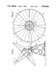
- FIG. 1 shows the total construction of a membrane concentration mirror 1 arranged on a support and pivotable around a horizontal axis 3 and a vertical axis 4.
- a receiver 5 of conventional construction is placed in the focus F of the membrane concentration mirror 1.
- the membrane concentrator mirror 1 in its top view is of the shape of a circular disk and consists of a plurality (five in the embodiment) of basic body segments.
- Each basic body segment 6 consists of a plurality of membrane segments 7.
- Each basic body segment 6 has a pipe union 13 for connection with a vacuum device.
- the pipe union 13 is only schematically shown in FIG. 3.
- the several basic body segments 6 are connected with the drive means 16 on the support 2 by means of a ring 14 and support ribs 15.
- each basic body segment 6 consists of a plurality of basic body sections, which each form supporting bodies for the accompanying membrane sections 7.
- Each basic body section 17 is formed by a slightly concave bottom wall 18, which consists of two parallel aluminium sheets 19, 20 the space between which is filled with a foam 21.
- Each bottom wall 18 or the side-shoulders 22, respectively, of the aluminium sheets 19, 20 are connected to side-walls 23.
- the outer rim 9 or 10, respectively, of a membrane section 7 is secured to the side of these side-walls 23 which is turned away from the bottom wall in a manner as described below.
- a U-profile 24 is secured to the outer side of each side-wall 23. It may be secured by means of screws or rivets 25.
- a tape adhesive on both sides 26 is arranged on the upper side of the U-profile.
- the outer rims 9, 10 of a membrane section 7 are secured to the adhesive tape 26 in such a way that the outer rims 9, 10 the cut of which is convex as shown in FIG. 9 are stretched straight.
- the membrane 8 of each membrane section 7 is put into the recess of the U-profile 24 as shown in FIG. 6 and then secured by means of an elastic rod 27 made for example from rubber the contour of which is adapted to fit the U-profile 24.
- a basic body segment 6 is accomplished which may for example comprise five basic body sections 17 as shown in FIG. 3.
- the cavity between the adjacent basic body sections 17 is filled with foam.
- each sidewall 23 is formed by a clamping profile, with each clamping device being formed by the U-profile 24 in connection with the elastic rod 27 and the Z-profile 29, and in addition the adhesive tape 26 and the screws or rivets 29, respectively.
- FIG. 8 is a sectional elevation in radial direction through basic body section 17 and simultaneously a side view of a side-wall 23 and thus a clamping profile. It shows that the space to be evacuated via the pipe union 13 is formed by the bottom wall 18, the radial outer end 33 and the radial inner end 34. The upper side is formed by the membrane 8. The upper edge 35 of each side-wall 23 of each clamping profile has a parabolic configuration. Thus is achieved a very defined optical geometry of the membrane concentrator mirror 1, with the desired optimal geometry also being defined in radial direction in contrast to conventional mirrors. Only in the inner area of the several membrane sections 7 the surface geometry is predetermined by the equilibrium status of the sub-pressure in each basic body section 17, of the membrane stress and of the air-pressure of the surrounding air.
- each membrane section 7 is anisotropic, i.e. it differs in radial and tangential direction, the outer rims 9, 10 of the membrane cut having a convex curvature and being stretched straight when secured.
- the ratio of the anisotropic stress of a stretched membrane section 7 or the total stress distribution of the stretched membrane section 7, respectively, may still be influenced by curving the radial inner and outer rims 39, 40 to the inside by a certain degree and, upon stretching, by securing them in accordance with the circular-segment-shaped outer contour 41 of each basic body section 17.
- the securing of the outer rims 39, 40 is effected by means of a corresponding profile of the outer end 33 in the same way as the securing of the radial outer rims 9, 10.
Landscapes
- Engineering & Computer Science (AREA)
- Physics & Mathematics (AREA)
- Life Sciences & Earth Sciences (AREA)
- Sustainable Development (AREA)
- Sustainable Energy (AREA)
- Thermal Sciences (AREA)
- Chemical & Material Sciences (AREA)
- Combustion & Propulsion (AREA)
- Mechanical Engineering (AREA)
- General Engineering & Computer Science (AREA)
- Optical Elements Other Than Lenses (AREA)
- Telescopes (AREA)
Abstract
A membrane concentrator mirror comprises a rigid, circular-segment-shaped frame-like basic body with a hermetically closed bottom wall, the basic body having a union device for connection with a conduit leading to a device for generating sub-pressure, a membrane being hermetically stretched over the basic body in such a way that it is deformable under the influence of a sub-pressure, and this membrane consisting of a plurality of membrane segments the outer end of which is limited in a circular segment shape, the membrane segments being connected with one another along radially extending rims. An improvement of the optical quality and a reliable connection of different membrane sections is to be achieved. To this effect the membrane segments are connected with one another in such a way that rigid, radially extending clamping profiles secure the radially extending outer rims by means of clamping devices.
Description
This is a continuation-in-part of our application Ser. No. 677,223 filed Dec. 3, 1984 and now abandoned.
The invention relates to a membrane concentrator mirror with a frame-like basic body, with a membrane stretched over the basic body.
Membrane parabolic dish mirrors which are formed by the pneumatic, hydraulic, electric, magnetic or electromagnetic deformation of originally plane membranes or individual membrane sections offer the basic advantage of low weight and easy construction as compared to conventional concentrator mirrors. These advantages are especially relevant in the case of the use of such concentrator mirrors for the concentration of sun energy.
Such a membrane concentrator mirror is known from U.S. Pat. No. 4,033,676, the membrane comprising a plurlaity of membrane sections. The membrane is exclusively secured along a circular outer rim of the basic body, so that the resulting mirror configuration corresponds exclusively to the equilibrium status of membrane stress and internal sub-pressure, and air-pressure of the surrounding air, respectively.
It is an object of the invention to increase optical quality and mechanical stability, and, simultaneously, to make it feasable to build mirrors that have a circular-segment-shaped basic body instead of a drum-shaped round basic body.
According to the invention the several membrane segments are connected with one another in such a way that rigid, radially extending clamping profiles clampingly secure the radially extending outer rims by means of radially extending clamping means. The clamping profiles extend over the inside of the drum-shaped basic body to meet in the centre where they are fixed to a circular supporting construction. These clamping profiles with the accompanying clamping means do not only ensure an absolutely safe, air-tight engagement of the outer rims of the membrane segments, but they also make possible an optical correction of the equilibrium configuration through a corresponding contour of paraboloid shape, for example,
Other objects, advantages and features of the present invention will appear from the detailed description of a preferred embodiment which will now be explained in conjunction with the accompanying drawings.
FIG. 1 shows a side view of the total construction of a membrane concentrator mirror according to the invention;
FIG. 2 shows a top view of the mirror;
FIG. 3 shows a top view in accordance with FIG. 2 of a mirror segment;
FIG. 4 is a perspective representation of the geometry of a mirror segment;
FIG. 5 shows a section through the joint area of the outer rims of two membrane segments or a clamping profile, respectively;
FIG. 6 is a part-sectioned representation in accordance with FIG. 5 showing the fastening of the outer rim of a membrane segment;
FIG. 7 shows a section according to FIG. 5 of two adjacent membrane segments before assembly;
FIG. 8 shows a sectional elevation in radial direction through a segment according to FIG. 7; and
FIG. 9 shows the geometry of the cut of a membrane segment.
FIG. 1 shows the total construction of a membrane concentration mirror 1 arranged on a support and pivotable around a horizontal axis 3 and a vertical axis 4. A receiver 5 of conventional construction is placed in the focus F of the membrane concentration mirror 1.
As can be seen from FIG. 2, the membrane concentrator mirror 1 in its top view is of the shape of a circular disk and consists of a plurality (five in the embodiment) of basic body segments.
Each basic body segment 6 consists of a plurality of membrane segments 7. The membrane segments 7, which consist of a fluor polymer foil 8 with a silver or aluminium layer, have rims 9, 10 extending radially straight in stressed condition and are limited by the circular segments 11 or 12, respectively, at their outer and inner ends.
Each basic body segment 6 has a pipe union 13 for connection with a vacuum device. The pipe union 13 is only schematically shown in FIG. 3. The several basic body segments 6 are connected with the drive means 16 on the support 2 by means of a ring 14 and support ribs 15.
In particular FIG. 7 shows that each basic body segment 6 consists of a plurality of basic body sections, which each form supporting bodies for the accompanying membrane sections 7. Each basic body section 17 is formed by a slightly concave bottom wall 18, which consists of two parallel aluminium sheets 19, 20 the space between which is filled with a foam 21. Each bottom wall 18 or the side-shoulders 22, respectively, of the aluminium sheets 19, 20 are connected to side-walls 23. The outer rim 9 or 10, respectively, of a membrane section 7 is secured to the side of these side-walls 23 which is turned away from the bottom wall in a manner as described below.
As can be seen from FIG. 5 and FIG. 6, a U-profile 24 is secured to the outer side of each side-wall 23. It may be secured by means of screws or rivets 25. On the upper side of the U-profile a tape adhesive on both sides 26 is arranged. As can be seen in particular from FIG. 6, the outer rims 9, 10 of a membrane section 7 are secured to the adhesive tape 26 in such a way that the outer rims 9, 10 the cut of which is convex as shown in FIG. 9 are stretched straight. The membrane 8 of each membrane section 7 is put into the recess of the U-profile 24 as shown in FIG. 6 and then secured by means of an elastic rod 27 made for example from rubber the contour of which is adapted to fit the U-profile 24. By means of riveting or screwing 28 as drafted in FIG. 5 and 6 an almost Z-shaped profile 29 is arranged, finally fixing the membrane section 7. Two adjacent basic body sections 17 are then connected with one another by adjoining the freely extending legs 30 of the Z-profiles 29 through screws or rivets 31. Thus, a basic body segment 6 is accomplished which may for example comprise five basic body sections 17 as shown in FIG. 3. The cavity between the adjacent basic body sections 17 is filled with foam.
It results from the afore-mentioned that each sidewall 23 is formed by a clamping profile, with each clamping device being formed by the U-profile 24 in connection with the elastic rod 27 and the Z-profile 29, and in addition the adhesive tape 26 and the screws or rivets 29, respectively.
FIG. 8 is a sectional elevation in radial direction through basic body section 17 and simultaneously a side view of a side-wall 23 and thus a clamping profile. It shows that the space to be evacuated via the pipe union 13 is formed by the bottom wall 18, the radial outer end 33 and the radial inner end 34. The upper side is formed by the membrane 8. The upper edge 35 of each side-wall 23 of each clamping profile has a parabolic configuration. Thus is achieved a very defined optical geometry of the membrane concentrator mirror 1, with the desired optimal geometry also being defined in radial direction in contrast to conventional mirrors. Only in the inner area of the several membrane sections 7 the surface geometry is predetermined by the equilibrium status of the sub-pressure in each basic body section 17, of the membrane stress and of the air-pressure of the surrounding air.
The stress distribution in each membrane section 7 is anisotropic, i.e. it differs in radial and tangential direction, the outer rims 9, 10 of the membrane cut having a convex curvature and being stretched straight when secured. The ratio of the anisotropic stress of a stretched membrane section 7 or the total stress distribution of the stretched membrane section 7, respectively, may still be influenced by curving the radial inner and outer rims 39, 40 to the inside by a certain degree and, upon stretching, by securing them in accordance with the circular-segment-shaped outer contour 41 of each basic body section 17. The securing of the outer rims 39, 40 is effected by means of a corresponding profile of the outer end 33 in the same way as the securing of the radial outer rims 9, 10.
Claims (7)
1. Membrane concentrator mirror comprising a rigid basic frame body with an air-tight closed bottom wall, said basic body comprising a device for connection with a conduit leading to device for generating sub-pressure, a membrane being hermetically stretched over said basic frame body said membrane being deformable under the influence of a sub-pressure, and consisting of a plurality of membrane segments and having an outer rim with a circular segment shape, said membrane segments being connected with one another along radially extending rims, characterized in that the membrane segments are connected with one another by rigid clamping profiles extending radially across said frame body, each of said clamping profiles being provided with clamping devices which secure the radially extending outer rims of adjacent membrane segments and which have a parabolic or approximately parabolic curvature.
2. Membrane concentrator mirror according to claim 1, characterized in that the clamping devices comprise a U-profile structure to be fixed to the clamping profile, that an elastic rod is surrounded by said outer rim of said membrane segments, and that said elastic rod is inserted in said U-profile structure together with said outer rim of said membrane segment.
3. Membrane concentrator mirror according to claim 1, characterized in that the bottom wall consists of aluminum.
4. Membrane concentrator mirror according to claim 1, characterized in that the bottom wall is laminated with hard foam.
5. Membrane concentrator mirror according to claim 1, characterized in that the membrane sections are formed by a foil consisting of a fluor polymer, said foil being covered by a silver or aluminum layer.
6. Membrane concentrator mirror according to claim 1, characterized in that the membrane segment after clamping same by said clamping devices are stressed more in a tangential direction than in a radial direction.
7. Membrane concentrator mirror according to claim 1, characterized in that the clamping devices comprise an adhesive tape.
Priority Applications (1)
| Application Number | Priority Date | Filing Date | Title |
|---|---|---|---|
| DE19873721114 DE3721114A1 (en) | 1986-11-13 | 1987-06-26 | Membrane concentration mirror |
Applications Claiming Priority (2)
| Application Number | Priority Date | Filing Date | Title |
|---|---|---|---|
| DE3344195A DE3344195C2 (en) | 1983-12-07 | 1983-12-07 | Membrane concentration level |
| DE3344195 | 1983-12-07 |
Related Parent Applications (1)
| Application Number | Title | Priority Date | Filing Date |
|---|---|---|---|
| US06677223 Continuation-In-Part | 1984-12-03 |
Publications (1)
| Publication Number | Publication Date |
|---|---|
| US4744644A true US4744644A (en) | 1988-05-17 |
Family
ID=6216237
Family Applications (1)
| Application Number | Title | Priority Date | Filing Date |
|---|---|---|---|
| US06/930,795 Expired - Fee Related US4744644A (en) | 1983-12-07 | 1986-11-13 | Membrane concentrator mirror |
Country Status (3)
| Country | Link |
|---|---|
| US (1) | US4744644A (en) |
| EP (1) | EP0144967A3 (en) |
| DE (1) | DE3344195C2 (en) |
Cited By (3)
| Publication number | Priority date | Publication date | Assignee | Title |
|---|---|---|---|---|
| US6075200A (en) * | 1999-06-30 | 2000-06-13 | Entech, Inc. | Stretched Fresnel lens solar concentrator for space power |
| US20060193066A1 (en) * | 2005-02-01 | 2006-08-31 | Prueitt Melvin L | Concentrating solar power |
| USD820196S1 (en) * | 2015-11-03 | 2018-06-12 | United Sun Systems Sweden Ab | Station for production/storage of solar energy |
Families Citing this family (2)
| Publication number | Priority date | Publication date | Assignee | Title |
|---|---|---|---|---|
| DE3721114A1 (en) * | 1986-11-13 | 1988-05-19 | Kleinwaechter Juergen | Membrane concentration mirror |
| CN102566004B (en) * | 2012-03-05 | 2013-08-28 | 南京科远自动化集团股份有限公司 | Overlap-connected shape-adjusting device used for reflecting mirror for heliostat |
Citations (4)
| Publication number | Priority date | Publication date | Assignee | Title |
|---|---|---|---|---|
| US3056131A (en) * | 1956-10-01 | 1962-09-25 | Collins Radio Co | Inflatable antenna |
| US3552835A (en) * | 1968-02-22 | 1971-01-05 | British Aircraft Corp Ltd | Retaining strip and channel for stretched reflector |
| US3623796A (en) * | 1968-10-30 | 1971-11-30 | Schweiger & Schweiger Ag | Mirror with adjustable focal length |
| US4033676A (en) * | 1976-01-21 | 1977-07-05 | Brantley Jr Lott W | Pressure-shaped reflector apparatus |
Family Cites Families (9)
| Publication number | Priority date | Publication date | Assignee | Title |
|---|---|---|---|---|
| DE2506905A1 (en) * | 1975-02-19 | 1976-08-26 | Doering Geb Thurnhofer Karolin | Parabolic mirror assembly for sunlight concentration - has mirror coated plastics foil and rigid annular edge structure |
| US4035064A (en) * | 1975-03-20 | 1977-07-12 | Minnesota Mining And Manufacturing Company | Light concentrator having an anticlastic reflective surface |
| DE2740813A1 (en) * | 1977-09-10 | 1979-03-22 | Leonhardt Fritz | REFLECTOR |
| US4226506A (en) * | 1978-04-10 | 1980-10-07 | Saint-Gobain Industries | Swiveling solar reflector with multiple reflecting elements supported by prefabricated cambered members |
| MA18582A1 (en) * | 1978-09-20 | 1980-04-01 | Grp D Interet Economique Semed | FOCUSING MIRROR WITH ADJUSTABLE FOCUSING |
| IT1128006B (en) * | 1979-02-09 | 1986-05-28 | Bfg Glassgroup | MIRRORS PRODUCTION |
| FR2483064A1 (en) * | 1980-05-23 | 1981-11-27 | Carbonaro Henri | Parabolic solar heat collector - has thin reflecting surfaces mounted on parabolic support rotatable about axis |
| US4293192A (en) * | 1980-05-27 | 1981-10-06 | Bronstein Allen I | Solar reflector with flexible sheet tightly secured around form surfaces |
| DE3127222A1 (en) * | 1981-07-10 | 1983-02-03 | Bomin-Solar GmbH & Co KG, 7850 Lörrach | EXTREMELY LIGHT, LARGE AREA COLLECTOR MIRROR WITH ELECTRIC, MAGNETIC OR ELASTIC MIRRORS MOLDED BY LIGHT PRESSURE. |
-
1983
- 1983-12-07 DE DE3344195A patent/DE3344195C2/en not_active Expired - Fee Related
-
1984
- 1984-12-04 EP EP84114757A patent/EP0144967A3/en not_active Withdrawn
-
1986
- 1986-11-13 US US06/930,795 patent/US4744644A/en not_active Expired - Fee Related
Patent Citations (4)
| Publication number | Priority date | Publication date | Assignee | Title |
|---|---|---|---|---|
| US3056131A (en) * | 1956-10-01 | 1962-09-25 | Collins Radio Co | Inflatable antenna |
| US3552835A (en) * | 1968-02-22 | 1971-01-05 | British Aircraft Corp Ltd | Retaining strip and channel for stretched reflector |
| US3623796A (en) * | 1968-10-30 | 1971-11-30 | Schweiger & Schweiger Ag | Mirror with adjustable focal length |
| US4033676A (en) * | 1976-01-21 | 1977-07-05 | Brantley Jr Lott W | Pressure-shaped reflector apparatus |
Cited By (3)
| Publication number | Priority date | Publication date | Assignee | Title |
|---|---|---|---|---|
| US6075200A (en) * | 1999-06-30 | 2000-06-13 | Entech, Inc. | Stretched Fresnel lens solar concentrator for space power |
| US20060193066A1 (en) * | 2005-02-01 | 2006-08-31 | Prueitt Melvin L | Concentrating solar power |
| USD820196S1 (en) * | 2015-11-03 | 2018-06-12 | United Sun Systems Sweden Ab | Station for production/storage of solar energy |
Also Published As
| Publication number | Publication date |
|---|---|
| EP0144967A2 (en) | 1985-06-19 |
| DE3344195C2 (en) | 1995-08-03 |
| DE3344195A1 (en) | 1985-06-13 |
| EP0144967A3 (en) | 1987-04-22 |
Similar Documents
| Publication | Publication Date | Title |
|---|---|---|
| US4432342A (en) | Inflatable solar collector | |
| US5365920A (en) | Solar concentrator system | |
| US4487196A (en) | Focusing solar collector and method for manufacturing same | |
| US4568156A (en) | Tracking apparatus for parabolic reflectors | |
| US4744644A (en) | Membrane concentrator mirror | |
| US4352112A (en) | Reflector with air pressure means | |
| JP2004072764A (en) | Extendable antenna reflector | |
| EP0194262A1 (en) | Assembling inflatable boat | |
| EP1645163B1 (en) | Diaphragms for loudspeaker drive units | |
| US6771229B2 (en) | Inflatable reflector | |
| JPH1071996A (en) | Modular unit constituting airship, and airship | |
| CA2357478C (en) | Window with a lens for an aircraft door | |
| US3295512A (en) | Foldable solar concentrator | |
| US4372772A (en) | Parabolic reflector comprising a plurality of triangular reflecting members forming a reflecting surface supported by a framework having a particular geometric pattern | |
| US4295709A (en) | Parabolic reflector comprising a plurality of triangular reflecting members forming a reflecting surface supported by a framework having a particular geometric pattern | |
| US3585955A (en) | Asymmetric catamaran | |
| US20020100221A1 (en) | Inflatable reflecting screen | |
| CN214930569U (en) | Antenna radome, antenna module and unmanned aerial vehicle | |
| US5237337A (en) | Method and apparatus for manufacturing and erecting concave metallic membrane type reflectors | |
| EP0821797B1 (en) | A method of constructing a thin film mirror | |
| US3125758A (en) | koehler | |
| JP2580277Y2 (en) | Radar reflector | |
| CN112072268B (en) | An antenna with an inflatable base | |
| EP0599893B1 (en) | Bi-elliptical flying toy | |
| US4296732A (en) | Solar radiation collector |
Legal Events
| Date | Code | Title | Description |
|---|---|---|---|
| FEPP | Fee payment procedure |
Free format text: PAYOR NUMBER ASSIGNED (ORIGINAL EVENT CODE: ASPN); ENTITY STATUS OF PATENT OWNER: SMALL ENTITY |
|
| FPAY | Fee payment |
Year of fee payment: 4 |
|
| FEPP | Fee payment procedure |
Free format text: PAYER NUMBER DE-ASSIGNED (ORIGINAL EVENT CODE: RMPN); ENTITY STATUS OF PATENT OWNER: SMALL ENTITY Free format text: PAYOR NUMBER ASSIGNED (ORIGINAL EVENT CODE: ASPN); ENTITY STATUS OF PATENT OWNER: SMALL ENTITY |
|
| REMI | Maintenance fee reminder mailed | ||
| LAPS | Lapse for failure to pay maintenance fees | ||
| FP | Lapsed due to failure to pay maintenance fee |
Effective date: 19960522 |
|
| STCH | Information on status: patent discontinuation |
Free format text: PATENT EXPIRED DUE TO NONPAYMENT OF MAINTENANCE FEES UNDER 37 CFR 1.362 |