US4739669A - Driving apparatus for industrial robot - Google Patents
Driving apparatus for industrial robot Download PDFInfo
- Publication number
- US4739669A US4739669A US06/809,938 US80993885A US4739669A US 4739669 A US4739669 A US 4739669A US 80993885 A US80993885 A US 80993885A US 4739669 A US4739669 A US 4739669A
- Authority
- US
- United States
- Prior art keywords
- ball screw
- frame
- slide member
- bracket
- linear movement
- Prior art date
- Legal status (The legal status is an assumption and is not a legal conclusion. Google has not performed a legal analysis and makes no representation as to the accuracy of the status listed.)
- Expired - Fee Related
Links
Images

Classifications
-
- B—PERFORMING OPERATIONS; TRANSPORTING
- B25—HAND TOOLS; PORTABLE POWER-DRIVEN TOOLS; MANIPULATORS
- B25J—MANIPULATORS; CHAMBERS PROVIDED WITH MANIPULATION DEVICES
- B25J9/00—Programme-controlled manipulators
- B25J9/10—Programme-controlled manipulators characterised by positioning means for manipulator elements
- B25J9/108—Bearings specially adapted therefor
-
- B—PERFORMING OPERATIONS; TRANSPORTING
- B23—MACHINE TOOLS; METAL-WORKING NOT OTHERWISE PROVIDED FOR
- B23Q—DETAILS, COMPONENTS, OR ACCESSORIES FOR MACHINE TOOLS, e.g. ARRANGEMENTS FOR COPYING OR CONTROLLING; MACHINE TOOLS IN GENERAL CHARACTERISED BY THE CONSTRUCTION OF PARTICULAR DETAILS OR COMPONENTS; COMBINATIONS OR ASSOCIATIONS OF METAL-WORKING MACHINES, NOT DIRECTED TO A PARTICULAR RESULT
- B23Q5/00—Driving or feeding mechanisms; Control arrangements therefor
- B23Q5/22—Feeding members carrying tools or work
- B23Q5/34—Feeding other members supporting tools or work, e.g. saddles, tool-slides, through mechanical transmission
- B23Q5/38—Feeding other members supporting tools or work, e.g. saddles, tool-slides, through mechanical transmission feeding continuously
- B23Q5/40—Feeding other members supporting tools or work, e.g. saddles, tool-slides, through mechanical transmission feeding continuously by feed shaft, e.g. lead screw
- B23Q5/404—Screw bearings therefor
-
- B—PERFORMING OPERATIONS; TRANSPORTING
- B25—HAND TOOLS; PORTABLE POWER-DRIVEN TOOLS; MANIPULATORS
- B25J—MANIPULATORS; CHAMBERS PROVIDED WITH MANIPULATION DEVICES
- B25J18/00—Arms
- B25J18/02—Arms extensible
- B25J18/025—Arms extensible telescopic
-
- F—MECHANICAL ENGINEERING; LIGHTING; HEATING; WEAPONS; BLASTING
- F16—ENGINEERING ELEMENTS AND UNITS; GENERAL MEASURES FOR PRODUCING AND MAINTAINING EFFECTIVE FUNCTIONING OF MACHINES OR INSTALLATIONS; THERMAL INSULATION IN GENERAL
- F16H—GEARING
- F16H25/00—Gearings comprising primarily only cams, cam-followers and screw-and-nut mechanisms
- F16H25/18—Gearings comprising primarily only cams, cam-followers and screw-and-nut mechanisms for conveying or interconverting oscillating or reciprocating motions
- F16H25/20—Screw mechanisms
- F16H2025/2062—Arrangements for driving the actuator
- F16H2025/2081—Parallel arrangement of drive motor to screw axis
-
- F—MECHANICAL ENGINEERING; LIGHTING; HEATING; WEAPONS; BLASTING
- F16—ENGINEERING ELEMENTS AND UNITS; GENERAL MEASURES FOR PRODUCING AND MAINTAINING EFFECTIVE FUNCTIONING OF MACHINES OR INSTALLATIONS; THERMAL INSULATION IN GENERAL
- F16H—GEARING
- F16H25/00—Gearings comprising primarily only cams, cam-followers and screw-and-nut mechanisms
- F16H25/18—Gearings comprising primarily only cams, cam-followers and screw-and-nut mechanisms for conveying or interconverting oscillating or reciprocating motions
- F16H25/20—Screw mechanisms
- F16H25/22—Screw mechanisms with balls, rollers, or similar members between the co-operating parts; Elements essential to the use of such members
- F16H25/2204—Screw mechanisms with balls, rollers, or similar members between the co-operating parts; Elements essential to the use of such members with balls
-
- Y—GENERAL TAGGING OF NEW TECHNOLOGICAL DEVELOPMENTS; GENERAL TAGGING OF CROSS-SECTIONAL TECHNOLOGIES SPANNING OVER SEVERAL SECTIONS OF THE IPC; TECHNICAL SUBJECTS COVERED BY FORMER USPC CROSS-REFERENCE ART COLLECTIONS [XRACs] AND DIGESTS
- Y10—TECHNICAL SUBJECTS COVERED BY FORMER USPC
- Y10T—TECHNICAL SUBJECTS COVERED BY FORMER US CLASSIFICATION
- Y10T74/00—Machine element or mechanism
- Y10T74/18—Mechanical movements
- Y10T74/18568—Reciprocating or oscillating to or from alternating rotary
- Y10T74/18576—Reciprocating or oscillating to or from alternating rotary including screw and nut
- Y10T74/18656—Carriage surrounded, guided, and primarily supported by member other than screw [e.g., linear guide, etc.]
-
- Y—GENERAL TAGGING OF NEW TECHNOLOGICAL DEVELOPMENTS; GENERAL TAGGING OF CROSS-SECTIONAL TECHNOLOGIES SPANNING OVER SEVERAL SECTIONS OF THE IPC; TECHNICAL SUBJECTS COVERED BY FORMER USPC CROSS-REFERENCE ART COLLECTIONS [XRACs] AND DIGESTS
- Y10—TECHNICAL SUBJECTS COVERED BY FORMER USPC
- Y10T—TECHNICAL SUBJECTS COVERED BY FORMER US CLASSIFICATION
- Y10T74/00—Machine element or mechanism
- Y10T74/18—Mechanical movements
- Y10T74/18568—Reciprocating or oscillating to or from alternating rotary
- Y10T74/18576—Reciprocating or oscillating to or from alternating rotary including screw and nut
- Y10T74/1868—Deflection related
Definitions
- This invention relates to a driving apparatus for an industrial robot, especially to a ball screw sustaining or supporting construction which allows to easily carry out the assembly thereof.
- the one end of the ball screw for driving the slide shaft is rotatably mounted on a bracket which is fixedly mounted on the end of the frame.
- This invention is intended to settle the problems as effectively as possible, wherein the bracket for rotatably mounting one end of the ball screw shaft is mounted on the frame so as to effect a fine adjustment in the radial direction of the ball screw and further, the bearings having the flexibility to the radial displacement are interposed between the bracket and one end of the ball screw shaft.
- the bracket is adjustably secured to the frame so as to be adequately displaced to align the center of the ball screw with the center of the slide shaft whereby even if the displacement occurs, by means of the thrust bearing and the like provided between the ball screw shaft and the bracket, the transverse or radial displacement and strain in the ball screw sustaining portion can be absorbed.
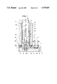
- FIG. 1 is a side view
- FIG. 2 is an enlarged cross-sectional view of the sustaining portion of the bracket
- FIG. 3 is a plain view which shows an arrangement of a roller follower of the slide shaft.
- FIG. 1 shows a cross-sectional side view of an embodiment suitable for the invention.
- 1 is a base and 2 is a frame which is secured to the base 1 as a whole by means of bolts B 1 , B 2 .
- 3 is a cylindrically-shaped hollow slide shaft or member which is slidably disposed within the frame 2, on the driving end of which an industrial robot apparatus and a manipulator and the like (not shown) are arranged to undergo linear movement.
- 4 is a plurality of roller followers, each of which is rotationally mounted within the frame 2 and the outer circumferential surface of which abuts on the slide shaft 3 so as to function as bearing.
- 5 is a ball nut which is fixedly mounted in the slide shaft or member 3 via a bracket 3a.
- 6 is a ball screw which is insertably threaded through the ball nut 5 and extends axially inside the slide shaft.
- 7 is a bracket which is secured to the frame 1 by means of bolts B 3 and B 4 .
- the bolts B 3 and B 4 as shown in FIG. 2, pass through a large through-hole 7a of the bracket 7 and are secured to the frame 2.
- the bracket 7 is movably adjustable relative to the frame 2 by the clearance between the bolts B 3 and B 4 and the large hole 7a.
- 8 and 9 are respectively radial bearings which are disposed in the bracket 7 so as to rotatably receive therein the ball screw shaft 6a and firmly pivotally mount the ball screw shaft 6a together with a bearing nut 9a.
- 10 is a thrust bearing which is interposed between the inside surface of the recess 7b of the bracket 7 (the surface parallel to the periphery of the frame 2) and the end portion 6b of the ball screw shaft 6a adjacent to the rear end of the ball screw 6, but if an angular bearing has some flexibility in the radial direction of the ball screw shaft 6a, the angular bearing can be used in place of the thrust bearing.
- 11 is a motor which is fixedly mounted on the base 1 via bolts B 5 and B 6 and rotatably drives the ball screw 6 in opposite directions via a pulley 12 which is fixedly engaged with the motor shaft, a timing belt 13 and a pulley 14 which is fixedly mounted around the ball screw shaft 6a.
- 15 is a cross-sectionally rail-shaped stopper or longitudinal element which is fixedly mounted on the outer peripheral portion of the slide shaft 3 by means of bolts (not shown).
- 16 is a cam follower which is rotatably mounted within the frame 2 and guides the stopper 15 in such a manner that the pair of cam followers receive therebetween the stopper 15 to press the same at both sides thereof, as shown in FIG. 3.
- the frame 2 is provided with a groove 2a for removing the stopper 15.
- the slide shaft 3 is, as well known, guided by the roller follower 4 and cam follower 16 such that it is vertically axially driven by the drive torque of the motor 11 without undergoing rotation.
- the thrust bearing 10 is intermediately provided in the recess 7b of the bracket 7 such that the transverse or radial displacement and strain, which occurs in the end portion 6b of the ball screw shaft 6a due to the displacement thereof, can be absorbed. Accordingly, the stress which is applied to the outer peripheral surface of the slide shaft 3 by the roller follower 4 and the cam follower 16 is averaged.
- the slide shaft 3 is inserted from the upper opening of the frame 2 as shown in FIG. 1 and the ball screw 6 is inserted from the lower opening so as to thread through the ball nut 5 and thereafter, the bracket 7 is adjustably mounted on the frame 2. Accordingly, the slide shaft 3 and the ball screw 6 can be easily assembled from the upper and/or lower openings respectively.
- the brackt 7 can be adjusted so as to match the center of the slide shaft 3 with the center of the ball screw 6 by moving the bracket a little relative to the frame by the clearance of the large hole 70.
- the ball screw is caused to be adjustable in the radial direction by mounting the ball screw on the frame so as to enable a fine adjustment in the radial direction of the ball screw.
- the bracket pivotally supports one end of the ball screw shaft on the frame, and further, bearings having sufficient radial flexibility so as to undergo radial displacement are interposed between the bracket and one end of the ball screw shaft connected to the ball screw such that in mounting the ball screw within the slide shaft, the ball screw can be easily assembled from the frame opening. Further, it becomes possible to absorb the transverse or radial displacement and strain which occurs in the sustaining portion of the ball screw due to the displacement between the center line of the slide shaft and the center line of the ball screw by means of the radial flexibility of the bearings. Therefore, it becomes possible to provide an industrial robot which is easily assembled without affecting the axial drive of the slide shaft.
Abstract
Description
Claims (6)
Applications Claiming Priority (2)
| Application Number | Priority Date | Filing Date | Title |
|---|---|---|---|
| JP59-265652 | 1984-12-17 | ||
| JP59265652A JPS61144462A (en) | 1984-12-17 | 1984-12-17 | Drive unit for industrial robot |
Publications (1)
| Publication Number | Publication Date |
|---|---|
| US4739669A true US4739669A (en) | 1988-04-26 |
Family
ID=17420108
Family Applications (1)
| Application Number | Title | Priority Date | Filing Date |
|---|---|---|---|
| US06/809,938 Expired - Fee Related US4739669A (en) | 1984-12-17 | 1985-12-17 | Driving apparatus for industrial robot |
Country Status (2)
| Country | Link |
|---|---|
| US (1) | US4739669A (en) |
| JP (1) | JPS61144462A (en) |
Cited By (19)
| Publication number | Priority date | Publication date | Assignee | Title |
|---|---|---|---|---|
| US4788871A (en) * | 1986-08-14 | 1988-12-06 | Steeltin Can Corporation | Probe for sensing temperature and/or pressure |
| US4876905A (en) * | 1987-07-28 | 1989-10-31 | U.S. Philips Corporation | Positioning arrangement for a measuring-value sensor |
| US4995278A (en) * | 1989-08-04 | 1991-02-26 | Huang Yung C | Car mark emblem display and storage device |
| US5148714A (en) * | 1990-10-24 | 1992-09-22 | Ag Processing Technology, Inc. | Rotary/linear actuator for closed chamber, and reaction chamber utilizing same |
| US5476338A (en) * | 1993-10-25 | 1995-12-19 | Build-It Engineering Company, Inc. | Vehicle parking or passageway security barrier |
| EP0767526A1 (en) * | 1995-10-03 | 1997-04-09 | Smc Kabushiki Kaisha | Electric actuator |
| EP0811461A1 (en) * | 1996-06-07 | 1997-12-10 | SMC Kabushiki Kaisha | Electric Actuator |
| US5769184A (en) * | 1996-09-27 | 1998-06-23 | Brooks Automation, Inc. | Coaxial drive elevator |
| EP1010498A1 (en) * | 1997-06-09 | 2000-06-21 | Kabushiki Kaisha Yaskawa Denki | Industrial robot |
| US6109125A (en) * | 1996-06-04 | 2000-08-29 | Precitec Gmbh | Linear drive mechanism including a slip clutch |
| US6178837B1 (en) * | 1996-12-25 | 2001-01-30 | Smc Kabushiki Kaisha | Electric actuator |
| US20100275710A1 (en) * | 2005-11-15 | 2010-11-04 | Honeywell International, Inc. | Ballscrew with an integral high-efficiency thrust bearing |
| CN102689311A (en) * | 2012-05-31 | 2012-09-26 | 江苏长虹汽车装备集团有限公司 | Robot arm stretching and swinging driving mechanism assembly |
| CN104209957A (en) * | 2014-09-06 | 2014-12-17 | 苏州神运机器人有限公司 | Telescopic arm applied to transfer robot |
| CN104209958A (en) * | 2014-09-06 | 2014-12-17 | 苏州神运机器人有限公司 | Transfer robot special for press |
| US20160108559A1 (en) * | 2014-10-16 | 2016-04-21 | Maschinenfabrik Rieter Ag | Bale Opener |
| CN109109014A (en) * | 2018-08-21 | 2019-01-01 | 北京芯合科技有限公司 | A kind of control system and method for variable-arm long industrial robot |
| US10507576B2 (en) * | 2015-09-24 | 2019-12-17 | Autonox Robotics Gmbh | Industrial robot |
| US20220316566A1 (en) * | 2019-06-17 | 2022-10-06 | Dewertokin Kft | Linear drive with positional orientation means between guide tube and spindle nut |
Families Citing this family (3)
| Publication number | Priority date | Publication date | Assignee | Title |
|---|---|---|---|---|
| JP4856420B2 (en) * | 2005-12-06 | 2012-01-18 | 株式会社ライト製作所 | Load port |
| JP6069146B2 (en) * | 2013-09-12 | 2017-02-01 | 本田技研工業株式会社 | Leg structure of legged mobile robot |
| CN104827488A (en) * | 2015-04-14 | 2015-08-12 | 马鞍山鼎泰稀土新材料股份有限公司 | Vertical position driving mechanism of four-freedom-degree high-speed conveying robot |
Citations (11)
| Publication number | Priority date | Publication date | Assignee | Title |
|---|---|---|---|---|
| GB394347A (en) * | 1931-12-18 | 1933-06-19 | Wilfred Nathan Waterworth Pier | Improvements relating to adjustable bearings for shafts |
| US2704693A (en) * | 1950-04-28 | 1955-03-22 | Ohio Crankshaft Co | Radially adjustable bearing support |
| US2817979A (en) * | 1955-02-24 | 1957-12-31 | Dean Peter Payne | Reciprocating screw actuator |
| US3069924A (en) * | 1959-08-18 | 1962-12-25 | Nippon Light Metal Co | Screw jack |
| DE1189351B (en) * | 1961-09-26 | 1965-03-18 | Licentia Gmbh | Add-on gear for low-error transmission of the rotary motion of an adjusting spindle of roll frames to the shaft of a sensitive transducer |
| US3559496A (en) * | 1967-07-26 | 1971-02-02 | Eisenhutte Prinz Rudolph Ag | Apparatus for transforming rotary motion into linear displacement and including a slip-type coupling |
| US3650583A (en) * | 1970-11-18 | 1972-03-21 | Artur Markovich Itin | Antifriction thrust bearing of a rotary table |
| US3792619A (en) * | 1972-08-31 | 1974-02-19 | R Cannon | Constant tension ball screw feed design |
| US3805629A (en) * | 1972-06-01 | 1974-04-23 | Usm Corp | Devices for linear and rotational movements |
| JPS57132944A (en) * | 1981-02-04 | 1982-08-17 | Mitsubishi Electric Corp | Feed screw supporter for main shaft feed of work machine |
| US4517853A (en) * | 1981-02-16 | 1985-05-21 | Toyama Machine Works, Limited | Balancing device |
-
1984
- 1984-12-17 JP JP59265652A patent/JPS61144462A/en active Pending
-
1985
- 1985-12-17 US US06/809,938 patent/US4739669A/en not_active Expired - Fee Related
Patent Citations (11)
| Publication number | Priority date | Publication date | Assignee | Title |
|---|---|---|---|---|
| GB394347A (en) * | 1931-12-18 | 1933-06-19 | Wilfred Nathan Waterworth Pier | Improvements relating to adjustable bearings for shafts |
| US2704693A (en) * | 1950-04-28 | 1955-03-22 | Ohio Crankshaft Co | Radially adjustable bearing support |
| US2817979A (en) * | 1955-02-24 | 1957-12-31 | Dean Peter Payne | Reciprocating screw actuator |
| US3069924A (en) * | 1959-08-18 | 1962-12-25 | Nippon Light Metal Co | Screw jack |
| DE1189351B (en) * | 1961-09-26 | 1965-03-18 | Licentia Gmbh | Add-on gear for low-error transmission of the rotary motion of an adjusting spindle of roll frames to the shaft of a sensitive transducer |
| US3559496A (en) * | 1967-07-26 | 1971-02-02 | Eisenhutte Prinz Rudolph Ag | Apparatus for transforming rotary motion into linear displacement and including a slip-type coupling |
| US3650583A (en) * | 1970-11-18 | 1972-03-21 | Artur Markovich Itin | Antifriction thrust bearing of a rotary table |
| US3805629A (en) * | 1972-06-01 | 1974-04-23 | Usm Corp | Devices for linear and rotational movements |
| US3792619A (en) * | 1972-08-31 | 1974-02-19 | R Cannon | Constant tension ball screw feed design |
| JPS57132944A (en) * | 1981-02-04 | 1982-08-17 | Mitsubishi Electric Corp | Feed screw supporter for main shaft feed of work machine |
| US4517853A (en) * | 1981-02-16 | 1985-05-21 | Toyama Machine Works, Limited | Balancing device |
Cited By (26)
| Publication number | Priority date | Publication date | Assignee | Title |
|---|---|---|---|---|
| US4788871A (en) * | 1986-08-14 | 1988-12-06 | Steeltin Can Corporation | Probe for sensing temperature and/or pressure |
| US4876905A (en) * | 1987-07-28 | 1989-10-31 | U.S. Philips Corporation | Positioning arrangement for a measuring-value sensor |
| US4995278A (en) * | 1989-08-04 | 1991-02-26 | Huang Yung C | Car mark emblem display and storage device |
| US5148714A (en) * | 1990-10-24 | 1992-09-22 | Ag Processing Technology, Inc. | Rotary/linear actuator for closed chamber, and reaction chamber utilizing same |
| US5476338A (en) * | 1993-10-25 | 1995-12-19 | Build-It Engineering Company, Inc. | Vehicle parking or passageway security barrier |
| EP0767526A1 (en) * | 1995-10-03 | 1997-04-09 | Smc Kabushiki Kaisha | Electric actuator |
| US5809831A (en) * | 1995-10-03 | 1998-09-22 | Smc Kabushiki Kaisha | Electric actuator |
| US6109125A (en) * | 1996-06-04 | 2000-08-29 | Precitec Gmbh | Linear drive mechanism including a slip clutch |
| EP0811461A1 (en) * | 1996-06-07 | 1997-12-10 | SMC Kabushiki Kaisha | Electric Actuator |
| US5796187A (en) * | 1996-06-07 | 1998-08-18 | Smc Kabushiki Kaisha | Electric actuator |
| US5769184A (en) * | 1996-09-27 | 1998-06-23 | Brooks Automation, Inc. | Coaxial drive elevator |
| US6178837B1 (en) * | 1996-12-25 | 2001-01-30 | Smc Kabushiki Kaisha | Electric actuator |
| EP1010498A1 (en) * | 1997-06-09 | 2000-06-21 | Kabushiki Kaisha Yaskawa Denki | Industrial robot |
| EP1010498A4 (en) * | 1997-06-09 | 2001-10-24 | Yaskawa Denki Seisakusho Kk | Industrial robot |
| US20100275710A1 (en) * | 2005-11-15 | 2010-11-04 | Honeywell International, Inc. | Ballscrew with an integral high-efficiency thrust bearing |
| US8015889B2 (en) * | 2005-11-15 | 2011-09-13 | Honeywell International Inc. | Ballscrew with an integral high-efficiency thrust bearing |
| CN102689311A (en) * | 2012-05-31 | 2012-09-26 | 江苏长虹汽车装备集团有限公司 | Robot arm stretching and swinging driving mechanism assembly |
| CN104209958A (en) * | 2014-09-06 | 2014-12-17 | 苏州神运机器人有限公司 | Transfer robot special for press |
| CN104209957A (en) * | 2014-09-06 | 2014-12-17 | 苏州神运机器人有限公司 | Telescopic arm applied to transfer robot |
| US20160108559A1 (en) * | 2014-10-16 | 2016-04-21 | Maschinenfabrik Rieter Ag | Bale Opener |
| CN105523387A (en) * | 2014-10-16 | 2016-04-27 | 里特机械公司 | Bale Opener |
| US10190238B2 (en) * | 2014-10-16 | 2019-01-29 | Maschinenfabrik Rieter Ag | Bale opener |
| US10507576B2 (en) * | 2015-09-24 | 2019-12-17 | Autonox Robotics Gmbh | Industrial robot |
| CN109109014A (en) * | 2018-08-21 | 2019-01-01 | 北京芯合科技有限公司 | A kind of control system and method for variable-arm long industrial robot |
| US20220316566A1 (en) * | 2019-06-17 | 2022-10-06 | Dewertokin Kft | Linear drive with positional orientation means between guide tube and spindle nut |
| US11852219B2 (en) * | 2019-06-17 | 2023-12-26 | Dewertokin Kft | Linear drive with positional orientation means between guide tube and spindle nut |
Also Published As
| Publication number | Publication date |
|---|---|
| JPS61144462A (en) | 1986-07-02 |
Similar Documents
| Publication | Publication Date | Title |
|---|---|---|
| US4739669A (en) | Driving apparatus for industrial robot | |
| JP3695784B2 (en) | Electric actuator | |
| US6382039B1 (en) | Telescopic system for a robot | |
| US20030041708A1 (en) | Vertical lathe, tool head for vertical lathe, rotary table apparatus for machine tool | |
| JPH079260B2 (en) | Combined movement guide device | |
| KR880000711B1 (en) | Positioning apparatus | |
| KR100433569B1 (en) | Rotating Table Apparatus | |
| JPH0761587B2 (en) | Transfer table using ball screw guide unit | |
| US4440038A (en) | Lead screw and follower assembly | |
| US4826128A (en) | Lifting platform guiding system, particularly for dynamically loaded platforms | |
| CN111511538B (en) | Press machine | |
| US6490956B1 (en) | Feeding apparatus of moved body | |
| US5024027A (en) | Tool mounting mechanism for a machine tool | |
| KR910002180B1 (en) | Roller bearing for linear sliding movement | |
| EP1282790B1 (en) | Tension device for traction means | |
| US5374222A (en) | Belt arrangement | |
| EP0004186B1 (en) | A servicing attachment for a carding machine | |
| EP0733406B1 (en) | Centrifuge with a drive unit and an endless transmission means | |
| CN218396647U (en) | Steel reinforcement cage locating wheel adjusting device | |
| KR920008795B1 (en) | Apparatus for setting a table for a belt-driven machine tool | |
| JPH08118269A (en) | Industrial robot | |
| CN216227595U (en) | Four-jaw chuck for laser pipe cutter | |
| JPH09329539A (en) | Capillary viscometer | |
| JP2001021019A (en) | Ball screw and driving device | |
| KR101618368B1 (en) | Weight balancer structure of machine tool |
Legal Events
| Date | Code | Title | Description |
|---|---|---|---|
| AS | Assignment |
Owner name: SEIKO INSTRUMENTS & ELECTRONICS LTD., 31-1, KAMEID Free format text: ASSIGNMENT OF ASSIGNORS INTEREST.;ASSIGNORS:YOKOSE, KAZUTOSHI;MAKISHIMA, YUTAKA;HIGAKE, MASATOSHI;AND OTHERS;REEL/FRAME:004834/0657 Effective date: 19871211 Owner name: SEIKO INSTRUMENTS & ELECTRONICS LTD., JAPAN Free format text: ASSIGNMENT OF ASSIGNORS INTEREST;ASSIGNORS:YOKOSE, KAZUTOSHI;MAKISHIMA, YUTAKA;HIGAKE, MASATOSHI;AND OTHERS;REEL/FRAME:004834/0657 Effective date: 19871211 |
|
| FEPP | Fee payment procedure |
Free format text: PAYOR NUMBER ASSIGNED (ORIGINAL EVENT CODE: ASPN); ENTITY STATUS OF PATENT OWNER: LARGE ENTITY |
|
| FPAY | Fee payment |
Year of fee payment: 4 |
|
| REMI | Maintenance fee reminder mailed | ||
| LAPS | Lapse for failure to pay maintenance fees | ||
| FP | Lapsed due to failure to pay maintenance fee |
Effective date: 19960501 |
|
| STCH | Information on status: patent discontinuation |
Free format text: PATENT EXPIRED DUE TO NONPAYMENT OF MAINTENANCE FEES UNDER 37 CFR 1.362 |