US473941A - Water-power - Google Patents
Water-power Download PDFInfo
- Publication number
- US473941A US473941A US473941DA US473941A US 473941 A US473941 A US 473941A US 473941D A US473941D A US 473941DA US 473941 A US473941 A US 473941A
- Authority
- US
- United States
- Prior art keywords
- wheel
- water
- shaft
- power
- bridge
- Prior art date
- Legal status (The legal status is an assumption and is not a legal conclusion. Google has not performed a legal analysis and makes no representation as to the accuracy of the status listed.)
- Expired - Lifetime
Links
- 244000000188 Vaccinium ovalifolium Species 0.000 description 3
- 235000000396 iron Nutrition 0.000 description 3
- 230000001105 regulatory effect Effects 0.000 description 2
- XLYOFNOQVPJJNP-UHFFFAOYSA-N water Substances O XLYOFNOQVPJJNP-UHFFFAOYSA-N 0.000 description 2
- 239000002184 metal Substances 0.000 description 1
- 238000007665 sagging Methods 0.000 description 1
Images


Classifications
-
- F—MECHANICAL ENGINEERING; LIGHTING; HEATING; WEAPONS; BLASTING
- F04—POSITIVE - DISPLACEMENT MACHINES FOR LIQUIDS; PUMPS FOR LIQUIDS OR ELASTIC FLUIDS
- F04D—NON-POSITIVE-DISPLACEMENT PUMPS
- F04D13/00—Pumping installations or systems
- F04D13/02—Units comprising pumps and their driving means
-
- Y—GENERAL TAGGING OF NEW TECHNOLOGICAL DEVELOPMENTS; GENERAL TAGGING OF CROSS-SECTIONAL TECHNOLOGIES SPANNING OVER SEVERAL SECTIONS OF THE IPC; TECHNICAL SUBJECTS COVERED BY FORMER USPC CROSS-REFERENCE ART COLLECTIONS [XRACs] AND DIGESTS
- Y10—TECHNICAL SUBJECTS COVERED BY FORMER USPC
- Y10S—TECHNICAL SUBJECTS COVERED BY FORMER USPC CROSS-REFERENCE ART COLLECTIONS [XRACs] AND DIGESTS
- Y10S415/00—Rotary kinetic fluid motors or pumps
- Y10S415/905—Natural fluid current motor
- Y10S415/906—Natural fluid current motor having specific features for water current
Definitions
- My present invention is in the nature of an improvement upon certain features of my application filed June 14,1889, Serial No. 314,293; and ithas for its object to provide better means of taking the power off of a very large, long, heavy, and slow-moving water-wheel, and at the same time in a measure supporting the wheel at its center and along its length.
- My devices are so arranged that additional working power may be applied at the part of the wheel where the current is the swiftest, as it is a well-known fact that the current in all rivers is swifter near their centers than near the banks, and in the use of a long heavy slow-moving water-wheel unless this is regulated there will be a constant tendency of the wheel to twist.
- the length of the belts can likewise be regulated by simply adding to or removing therefrom one or more of the links of each belt.
- A represents a water-wheel, which may be variously constructed, and is shown in the present instance as an undershot wheel having blades A preferably curved in the manner shown, although this forms no' particular feature of my present invention.
- This wheelA is shown as mounted between two piers P P, which piers support a bridge B above the wheel.
- Mounted on the bridge is a shaft C, to which are attached a number of small sprocket wheels 0, around which pass the link belts D, the belts also passing around the outside of the water-wheel at various distances apart, the wheel being furnished with a number of sprockets h, secured on the circumference thereof, with which the belts engage.
- the shaft F of the wheel is made upof a number of segments, four being shown in the present instance, and these segments are provided with flanges f, and between these flanges are placed the metal stiffening-bars g, which bars are made tapering from the center toward their edges, as clearly illustrated in Fig. 1.
- the shaft'C on the bridge may be a single shaft substantially the length of the wheel, or
Landscapes
- Engineering & Computer Science (AREA)
- Mechanical Engineering (AREA)
- General Engineering & Computer Science (AREA)
- Other Liquid Machine Or Engine Such As Wave Power Use (AREA)
Description
(No Model.) 3 Sheets-Sheet 1.
A..O. MATHER.
W'ATER POWER. I No. 473,941. Patented May 3, 1892.
(No Model.) 38heets-Sheet 2. A. 0. MATHER. WATER POWER.
No. 473,941.- Patented-M213 3, 1892.
(No Model.) 3 Sheets-Sheet 3. A. G. MATHER.
WATER POWER. 7 No. 473,941. v Patented Ma 3, 1892.
WITJVESSES INVEJVIOR WM J4 Mm .zlttorneys.
UNITED STATES PATENT OFFICE.
ALONZO C. MATHER, OF CHICAGO, ILLINOIS.
WATER-POWER.
SPECIFICATION forming part of Letters Patent No. 473,941, dated May 3, 1892.
Application filed November 1, 1890. Serial No. 370,056. (No model.)
To all whom it may concern.-
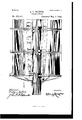
Be it known that I, ALONZO C. MATHER, a citizen of the United States, residing at Chicago, in the county of Cook and State of Illinois, have invented certain new and useful Improvements in Tater-Power, of which the following is a specification, reference being had to the accompanying drawings, of which- Figure 1 is a partial side view showing portions in section. Fig. 2 is an end view showing parts in section, and Fig. 3 is a side view showing the power in operative position.
My present invention is in the nature of an improvement upon certain features of my application filed June 14,1889, Serial No. 314,293; and ithas for its object to provide better means of taking the power off of a very large, long, heavy, and slow-moving water-wheel, and at the same time in a measure supporting the wheel at its center and along its length.
My devices are so arranged that additional working power may be applied at the part of the wheel where the current is the swiftest, as it is a well-known fact that the current in all rivers is swifter near their centers than near the banks, and in the use of a long heavy slow-moving water-wheel unless this is regulated there will be a constant tendency of the wheel to twist. In carrying out this part of my invention 1 overcome these objections by applying to the circumference of the wheel a number of rows of sprockets, which are distributed along the surface of the wheel at ten or twelve feet apart or otherwise, according to the requirements of each particular case, and connected with each series of sprockets is a link belt, which runs over one of a series of small sprocket-wheels secured to a shaft mounted above the water-wheel, as upon a bridge preferably supported on the piers between which the wheel operates. This shaft carrying the small sprocket-wheels can be connected to an air-compressor, dynamo, or other working machine in any desired way and need not be illustrated herein, one arrangement be ing shown in my former application. By this arrangement of sprockets and link belts distributed along the surface of the wheel it will be seen that the force of the current is applied more directly to the belts, and thence to the shaft, and the tendency of the wheel to twist is obviated. Furthermore, the link belts, passing around the wheel at its center and at proper distances at each side therefrom, tend to support the wheel and-prevent it sagging, and also aid in preventing the tendency to twist due to the uneven flow of the current at different parts of the wheel. Further, when the wheel is mounted, as described in my former patent, so that it can be raised or lowered,
according to the height of the water at various seasons of the year, the length of the belts can likewise be regulated by simply adding to or removing therefrom one or more of the links of each belt.
In order to further make a strong contactwheel which will not be liable to sag at the center or become twisted or distorted by the force of the current, I make the shaft of a number of longitudinal sections plated together, an d between the edges of these sections I place stiffening ribs or irons, and these irons are made tapering from their centers toward their ends in order to properly support the wheel, the width of the irons at the various points being a matter of. mathematical calculation, varying according to the weight and length of the wheel.
In the accompanying drawings, A represents a water-wheel, which may be variously constructed, and is shown in the present instance as an undershot wheel having blades A preferably curved in the manner shown, although this forms no' particular feature of my present invention. This wheelA is shown as mounted between two piers P P, which piers support a bridge B above the wheel. Mounted on the bridge is a shaft C, to which are attached a number of small sprocket wheels 0, around which pass the link belts D, the belts also passing around the outside of the water-wheel at various distances apart, the wheel being furnished with a number of sprockets h, secured on the circumference thereof, with which the belts engage. The shaft F of the wheel is made upof a number of segments, four being shown in the present instance, and these segments are provided with flanges f, and between these flanges are placed the metal stiffening-bars g, which bars are made tapering from the center toward their edges, as clearly illustrated in Fig. 1. The shaft'C on the bridge may be a single shaft substantially the length of the wheel, or
may be made up of separate sections and suppiers, the shaft of the Water-Wheel being made ported in suitable bearings on the bridge. in segments and provided with stiffening- What I claim ispieces between the segments tapering from. 15 1. The combination, with the piers supportthe center toward the ends of the wheels, and 5 ing the bridge, of a water-wheel suspended a series of link belts surrounding the wheel between the piers, a shaft on the bridge, and and connected with the shaft on the bridge, a series of link belts surrounding the wheel substantially as described. and connected to the shaft upon the bridge, substantially as described. 10 2. The combination,with the piers supporting the bridge, of a shaft supported on the bridge, a water-wheel suspended between the v ALONZO C. MATHER. Witnesses:
WILLIAM Y. Con, JOHN B. ALEXANDER.
Publications (1)
| Publication Number | Publication Date |
|---|---|
| US473941A true US473941A (en) | 1892-05-03 |
Family
ID=2542800
Family Applications (1)
| Application Number | Title | Priority Date | Filing Date |
|---|---|---|---|
| US473941D Expired - Lifetime US473941A (en) | Water-power |
Country Status (1)
| Country | Link |
|---|---|
| US (1) | US473941A (en) |
Cited By (1)
| Publication number | Priority date | Publication date | Assignee | Title |
|---|---|---|---|---|
| US3187502A (en) * | 1961-01-23 | 1965-06-08 | Gen Electric | Rocket nozzle |
-
0
- US US473941D patent/US473941A/en not_active Expired - Lifetime
Cited By (1)
| Publication number | Priority date | Publication date | Assignee | Title |
|---|---|---|---|---|
| US3187502A (en) * | 1961-01-23 | 1965-06-08 | Gen Electric | Rocket nozzle |
Similar Documents
| Publication | Publication Date | Title |
|---|---|---|
| US244221A (en) | Water-power | |
| US3804A (en) | Water-wheel | |
| US530118A (en) | Apparatus f | |
| US1030835A (en) | Current-power transmuter. | |
| US1224188A (en) | Grain-pan for threshing-machines. | |
| US308867A (en) | Gang-plank | |
| US212186A (en) | Improvement in water-wheels | |
| US730260A (en) | Water-elevator. | |
| US1333443A (en) | Tide-water power | |
| US921940A (en) | Water-power wheel. | |
| US807916A (en) | Elevator and conveyer. | |
| US1137156A (en) | Power mechanism for dam-spillways. | |
| US1443845A (en) | Current motor | |
| US174178A (en) | Improvement in endless-chain propellers | |
| US1049724A (en) | Current-motor. | |
| US633529A (en) | Paddle-wheel. | |
| US456266A (en) | Wave-power | |
| US1155881A (en) | Water-power. | |
| US434306A (en) | Water-wheel | |
| US170499A (en) | Improvement in water-wheels | |
| US1565910A (en) | Device for utilizing the power of flowing water | |
| US1075548A (en) | Conveyer. | |
| US687074A (en) | Water-motor. | |
| US723341A (en) | Draining-machine. | |
| US192563A (en) | Improvement in endless-chain propellers |