US4738044A - Light beam target designator - Google Patents
Light beam target designator Download PDFInfo
- Publication number
- US4738044A US4738044A US06/876,030 US87603086A US4738044A US 4738044 A US4738044 A US 4738044A US 87603086 A US87603086 A US 87603086A US 4738044 A US4738044 A US 4738044A
- Authority
- US
- United States
- Prior art keywords
- path
- enclosure
- along
- assembly
- aiming device
- Prior art date
- Legal status (The legal status is an assumption and is not a legal conclusion. Google has not performed a legal analysis and makes no representation as to the accuracy of the status listed.)
- Expired - Fee Related
Links
- 230000003287 optical effect Effects 0.000 description 3
- XKRFYHLGVUSROY-UHFFFAOYSA-N Argon Chemical compound [Ar] XKRFYHLGVUSROY-UHFFFAOYSA-N 0.000 description 2
- 230000001427 coherent effect Effects 0.000 description 2
- 238000010304 firing Methods 0.000 description 2
- 229910052786 argon Inorganic materials 0.000 description 1
- 238000011109 contamination Methods 0.000 description 1
- 239000000428 dust Substances 0.000 description 1
- CPBQJMYROZQQJC-UHFFFAOYSA-N helium neon Chemical compound [He].[Ne] CPBQJMYROZQQJC-UHFFFAOYSA-N 0.000 description 1
- 238000012986 modification Methods 0.000 description 1
- 230000004048 modification Effects 0.000 description 1
- 238000005192 partition Methods 0.000 description 1
- 239000007787 solid Substances 0.000 description 1
- 210000003813 thumb Anatomy 0.000 description 1
Images

Classifications
-
- F—MECHANICAL ENGINEERING; LIGHTING; HEATING; WEAPONS; BLASTING
- F41—WEAPONS
- F41G—WEAPON SIGHTS; AIMING
- F41G1/00—Sighting devices
- F41G1/32—Night sights, e.g. luminescent
- F41G1/34—Night sights, e.g. luminescent combined with light source, e.g. spot light
- F41G1/36—Night sights, e.g. luminescent combined with light source, e.g. spot light with infrared light source
-
- F—MECHANICAL ENGINEERING; LIGHTING; HEATING; WEAPONS; BLASTING
- F41—WEAPONS
- F41G—WEAPON SIGHTS; AIMING
- F41G1/00—Sighting devices
- F41G1/32—Night sights, e.g. luminescent
- F41G1/34—Night sights, e.g. luminescent combined with light source, e.g. spot light
- F41G1/35—Night sights, e.g. luminescent combined with light source, e.g. spot light for illuminating the target, e.g. flash lights
Definitions
- the present invention relates generally to device capable of projecting a light beam which assists in the aiming of a firearm. More particularly, the invention relates to such a light beam target designator having a pair of light sources and capable of selectively projecting either light sources through a common focusing and deflecting assembly.
- light beams have been used to assist in the aiming of firearms.
- Commercially available devices commonly employ lasers as a light source and are mounted on the firearm so that the laser beam is precisely aligned with the bore or shaft of the weapon.
- the laser is mounted within an enclosure, and the enclosure is adjustably attached to the firearm so that the alignment of the laser beam relative to the bore or shaft of the firearm may be adjusted to compensate for factors such as distance to the target, windage, and the like.
- laser target designators employ a visible light beam for use during daylight hours.
- the use of visible light beams at night is disadvantageous since it is often possible to trace a visible light beam back to its source. This is undesirable during military operations since it would allow the opposing forces to quickly identify the point of origin of the fire.
- laser target designators employing infrared beams have been developed. Such infrared beams are visible to those using infrared image intensifers, but invisible to all others. Such infrared target disignators may thus be used with relative safety at night.
- U.S. Pat. Nos. 4,291,478; 4,161,076; and 4,212,109 each disclose laser target designators employing a single light source.
- U.S. Pat. Nos. 3,918,813; 4,260,254; and 4,266,873 each disclose laser alignment systems which allow a user to view the laser beam through the laser focusing system.
- U.S. Pat. No. 4,385,834 discloses a wedge system for aligning a beam deflecting prism.
- a beam aiming device includes a first beam generator and a second beam generator mounted in an enclosure.
- a first mechanism is provided for aligning the first beam and the second beam along a common beam path
- a second mechanism is provided for adjustably deflecting a beam projected along the common beam path.
- Such deflection allows precise adjustment of the direction of the beam emanating from the enclosure regardless of which generator is its source.
- a first beam generator operating in the visible light region and a second beam generator operaing in the infrared light region visible and infrared designating beams may be projected in precisely the same direction. The user is thus able to switch between the visible light and infrared beams as the external light conditions warrant without having to change target designators and without loss of alignment accuracy.
- the first beam generator is a visible light laser and the second beam generator is an infrared laser.
- a mirror and beam splitter assembly is provided to align the two beams along a common path, while the beam deflecting mechanism comprises a conventional Galilean telescope having a focusing and a collimating lens.
- the lens assembly is mounted within the enclosure on a gimbal mounting assembly.
- a mechanism is provided for deflecting the lens assembly in one plane to adjust the azimuth of the beam and in the orthogonal plane to adjust the elevation of the beam.
- such adjustment mechanism may comprise a pair of tapered wedges mounted to translate axially on threaded shafts which are disposed parallel to the direction of focus of the lens assembly. The wedges, as they are moved forward and back on the shafts, act against rods which transmit force transversely to the lens assembly.
- FIG. 1 is a side elevational view of a laser target designator constructed according to the principles of the present invention shown in section.
- FIG. 2 is a detailed sectional view taken along line 2--2 of FIG. 1.
- FIG. 3 is a detailed sectional view taken along line 3--3 of FIG. 2.
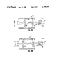
- FIGS. 4A and 4B are schematic views illustrating the operation of the lens assembly.
- a light beam target designator 10 constructed in accordance with the principles of the present invention includes an elongate enclosure 12 having a front piece 14 and rear cap 16.
- a first beam generator 20 and a second beam generator 22 are mounted within the enclosure. While both beam generators 20 and 22 will usually be lasers capable of producing a coherent light beam, other focused beam generators may also find use.
- the first beam generator 20 is a visible light laser, typically an argon or helium-neon laser capable of projecting a coherent beam along line 24.
- the second beam generator 22 is an infrared laser, typically a solid state laser, capable of projecting an infrared beam along line 26.
- the beams 24 and 26 are shown to be substantially parallel in projecting forward toward the front end piece 14 of the enclosure 12.
- a power supply 30 operates from batteries 32 to supply the necessary current for operating both beam generators 20 and 22.
- a switch 34 is provided on the rear cap 16 to allow the user to select between operation of beam generator 20 and beam generator 22. As will be seen, the nature of the light beam projected from the designator 10 depends on which beam generator 20 or 22 is operating.
- Rear cap 16 is further provided with a thumb screw 36 which allows the user to move the rear cap 16 to replace batteries 32.
- Both beam generators 20 and 22 are mounted on a partition wall 38 which separates a rear compartment 40 from a forward compartment 42 of the enclosure 12. In this way, the forward compartment 42, which contains all of the optical components of the designator 10, is sealed from the rear compartment 40 which may be opened. Thus, dust and other contamination which may enter the rear compartment 40 is prevented from entering the forward compartment and contaminating the optical equipment.
- a tube 46 is provided along one side of the enclosure 12.
- the tube 46 is useful for mounting the target designator 10 on a firearm, such as a rifle. Such mounting systems are well known and need not be described further.
- an optical deflecting assembly 50 is provided.
- the assembly 50 includes a mirrored prism 52 which receives the beam 26 and reflects it transversely toward visible light beam 24, and a pair of prisms 54 and 56 which provide for proper alignment of the infrared beam into a beam splitter 58.
- the beam splitter 58 reflects the infrared beam forward along precisely the same path which is taken by visible light beam 24. As the beam splitter 58 is a partially reflecting surface, the visible light beam 24 is able to penetrate through the beam splitter without deviation from the common path with the infrared beam.
- the light beam 24 or 26 (depending on which laser is on) then enters a lens assembly 60 which is capable of enlarging the beam to a desired width.
- the lens assembly 60 is mounted within mounting block 61 on a gimbal assembly.
- the gimbal assembly 62 includes a clevis 63 which is pivotally attached to block 61 by pin 64.
- the lens assembly 60 is pivotally mounted within the clevis 63 by pin 65.
- the lens assembly 60 may be directionally adjusted about two axes 90° apart to correct both the elevation and the azimuth of the beam by exerting a force in the desired direction on the assembly.
- a first tapered wedge 66 is mounted on a threaded shaft 67 which is received through the front piece 14 and passes through a bore 68 formed in mounting block 61.
- the wedge 66 receives shaft 67 through an axial threaded hole so that rotation of shaft 67 by turning head 68 causes the wedge 66 to translate forward or backward, depending on the direction of rotation.
- a second wedge 70 (FIG. 1) is mounted on a threaded shaft 72.
- the shaft 77 passes through a bore 74 formed in the mounting block 61 at a location 90° removed from the first threaded shaft 67. Rotation of threaded shaft 72 by head 76 causes forward and backward translation of the wedge 70.
- First wedge 66 engages a rod 80 which engages the upper surface of lens assembly 60.
- rotation of knob 68 which causes rearward translation of the wedge (toward the rear cap 16) an upward deflection of the lens assembly 60.
- Forward translation of the wedge 66 (toward front piece 14) conversely, causes a downward deflection of the lens assembly 60. In this way the elevation of the beam emanating from the lens assembly 60 may be adjusted.
- the lens assembly 60 typically includes a fixed focusing emanating from the beam splitter 58 (which may originate from either beams 24 or 26) pass through the focusing lens 90 and are focused to a point P within the lens assembly 60.
- the beams then diverge and pass through the collimating lens 92 which returns the beams to a parallel state having a width depending on the distance between lenses 90 and 92.
- a distance D 1 between the lenses results in a beam width W 1 .
- a greater beam width W 2 is achieved as illustrated in FIG. 4B.
- the light beam designator is mounted on a firearm, typically a pistol or rifle.
- the direction of the beam may then be set by aiming the beam and firing.
- the adjust knobs 68 and 76 may then be used to correct the elevation and azimuth of the beam so that it coincides with the actual firing direction. Subsequent adjustments may also be made for distance and windage. It is an advantage of the device of the present invention that once alignment is made for either the visible or infrared beams, no further adjustment is requred for the other beam.
Landscapes
- Physics & Mathematics (AREA)
- Optics & Photonics (AREA)
- Engineering & Computer Science (AREA)
- General Engineering & Computer Science (AREA)
- Optical Radar Systems And Details Thereof (AREA)
Abstract
Description
Claims (10)
Priority Applications (1)
| Application Number | Priority Date | Filing Date | Title |
|---|---|---|---|
| US06/876,030 US4738044A (en) | 1986-06-18 | 1986-06-18 | Light beam target designator |
Applications Claiming Priority (1)
| Application Number | Priority Date | Filing Date | Title |
|---|---|---|---|
| US06/876,030 US4738044A (en) | 1986-06-18 | 1986-06-18 | Light beam target designator |
Publications (1)
| Publication Number | Publication Date |
|---|---|
| US4738044A true US4738044A (en) | 1988-04-19 |
Family
ID=25366833
Family Applications (1)
| Application Number | Title | Priority Date | Filing Date |
|---|---|---|---|
| US06/876,030 Expired - Fee Related US4738044A (en) | 1986-06-18 | 1986-06-18 | Light beam target designator |
Country Status (1)
| Country | Link |
|---|---|
| US (1) | US4738044A (en) |
Cited By (42)
| Publication number | Priority date | Publication date | Assignee | Title |
|---|---|---|---|---|
| US4876816A (en) * | 1988-11-18 | 1989-10-31 | Triplett Melvin W | Target illuminating aiming system |
| US4991183A (en) * | 1990-03-02 | 1991-02-05 | Meyers Brad E | Target illuminators and systems employing same |
| US5033219A (en) * | 1990-02-06 | 1991-07-23 | Emerging Technologies, Inc. | Modular laser aiming system |
| US5036517A (en) * | 1990-03-02 | 1991-07-30 | Meyers Brad E | Target illuminators and systems employing same |
| US5042048A (en) * | 1990-03-02 | 1991-08-20 | Meyer Brad E | Target illuminators and systems employing same |
| US5056097A (en) * | 1990-03-02 | 1991-10-08 | Meyers Brad E | Target illuminators and systems employing same |
| US5307253A (en) * | 1992-12-09 | 1994-04-26 | Jehn E F | Structure of laser pointer |
| FR2700840A1 (en) * | 1992-12-21 | 1994-07-29 | Thomson Csf | Weapon with stabilized sight |
| US5355609A (en) * | 1992-12-04 | 1994-10-18 | Schenke Reynold A | Laser beam sighting apparatus with a selectively adjustable beam width |
| US5369888A (en) * | 1993-01-13 | 1994-12-06 | Kay; Ira M. | Wide field of view reflex gunsight |
| WO1995017640A1 (en) * | 1993-12-21 | 1995-06-29 | Thomson-Csf | Weapon with stabilised sight |
| US5452131A (en) * | 1993-03-10 | 1995-09-19 | Sandberg Development Aktiebolag | Sighting device for small arms, comprising a variable aperature |
| US5671561A (en) * | 1995-11-14 | 1997-09-30 | Emerging Technologies, Inc. | Modular, combination laser and electronic aiming system |
| USD452962S1 (en) | 2000-01-25 | 2002-01-15 | William H. Grube | Switch for a laser aiming light |
| US6363648B1 (en) | 2000-01-27 | 2002-04-02 | William H. Grube | Laser aiming light for firearms |
| US20030074824A1 (en) * | 2001-10-18 | 2003-04-24 | Sarl Patrick Arachequesne | Mount for a sighting device on a firearm |
| US6574901B1 (en) | 1998-07-02 | 2003-06-10 | Insight Technology Incorporated | Auxiliary device for a weapon and attachment thereof |
| US6650277B1 (en) * | 2002-08-12 | 2003-11-18 | The United States Of America As Represented By The Secretary Of The Navy | Target designation system |
| US6762710B2 (en) * | 2002-08-12 | 2004-07-13 | The United States Of America As Represented By The Secretary Of The Navy | Target designation system |
| US20040211105A1 (en) * | 2003-03-05 | 2004-10-28 | Patrick Arachequesne Sarl | Mounting a holographic sight on a firearm |
| US20050001756A1 (en) * | 2002-08-12 | 2005-01-06 | Wilkinson James A. | Target designation system |
| US20050000343A1 (en) * | 1999-02-05 | 2005-01-06 | Hitachi Koki Co., Ltd. | Cutter with laser generator that irradiates cutting position on workpiece to facilitate alignment of blade with cutting position |
| WO2005045349A1 (en) * | 2003-11-08 | 2005-05-19 | Hyun Joon Cho | Target designator |
| USD515118S1 (en) * | 2002-10-04 | 2006-02-14 | Gs Development | Sight with a light emitting device |
| US20060196099A1 (en) * | 2004-04-06 | 2006-09-07 | Surefire, Llc, A California Limited Liability Company | Accessory devices for firearms |
| US7117624B2 (en) | 2004-04-06 | 2006-10-10 | Surefire, Llc | Accessory devices for firearms |
| US20060265206A1 (en) * | 2001-09-07 | 2006-11-23 | Hitachi Koki Co., Ltd. | Portable circular power saw with optical alignment |
| US20070214701A1 (en) * | 2004-05-06 | 2007-09-20 | Insight Technology, Inc. | Weapon aiming device |
| US7325352B2 (en) | 2004-04-06 | 2008-02-05 | Surefire, Llc | Accessory devices for firearms |
| WO2009075489A1 (en) * | 2007-12-11 | 2009-06-18 | Korea Elecom Co., Ltd. | Laser transmitter for simulating a fire weapon and manufacturing method thereof |
| US20110232151A1 (en) * | 2010-03-29 | 2011-09-29 | Smith & Wesson Corp. | Integral, frame-mounted laser aiming device |
| US8067734B2 (en) * | 2006-08-11 | 2011-11-29 | Lasermax, Inc. | Target marker having quantum cascade laser for thermally marking a target |
| US8394016B1 (en) | 2009-07-02 | 2013-03-12 | Bruce Cabot Arné | Illuminated airway article |
| US8826582B2 (en) | 2011-11-26 | 2014-09-09 | Orval E. Bowman | Pointing devices, apparatus, systems and methods for high shock environments |
| US20160370148A1 (en) * | 2012-11-02 | 2016-12-22 | Umarex Usa, Inc. | Method and system for aligning a point of aim with a point of impact for a projectile device |
| US9638493B2 (en) | 2011-11-26 | 2017-05-02 | Orval E. Bowman | Pointing devices, apparatus, systems and methods for high shock environments |
| US9658031B1 (en) | 2011-12-19 | 2017-05-23 | Laser Aiming Systems Corporation | Auto on green laser sight |
| USD873946S1 (en) | 2018-01-04 | 2020-01-28 | Laser Aiming Systems Corporation | Firearm-mounted optical device |
| US11306987B2 (en) | 2016-10-14 | 2022-04-19 | Laser Aiming Systems Corporation | Gun-mounted recording device with auto on |
| US11750032B2 (en) | 2016-10-14 | 2023-09-05 | Laser Aiming Systems Corporation | Gun-mounted recording device |
| US12130121B1 (en) | 2020-07-21 | 2024-10-29 | Laser Aiming Systems Corporation | Data redundancy and hardware tracking system for gun-mounted recording device |
| US12173992B1 (en) | 2020-07-21 | 2024-12-24 | Laser Aiming Systems Corporation | Gun mounted recording device with quick release battery |
Citations (19)
| Publication number | Priority date | Publication date | Assignee | Title |
|---|---|---|---|---|
| US2653386A (en) * | 1952-06-17 | 1953-09-29 | James L Winton | Adjustable telescopic sight mount base |
| US3522992A (en) * | 1967-06-28 | 1970-08-04 | North American Rockwell | Geodetic survey system and digital phase-meter therefor |
| US3710798A (en) * | 1971-08-30 | 1973-01-16 | American Optical Corp | Laser system for microsurgery |
| US3752587A (en) * | 1971-09-09 | 1973-08-14 | Philco Ford Corp | Apparatus for boresighting a laser beam emitter device |
| US3803399A (en) * | 1972-07-20 | 1974-04-09 | Us Army | Target illuminator |
| US3918813A (en) * | 1973-03-28 | 1975-11-11 | Commw Of Australia | Optical collimating alignment units |
| US4125755A (en) * | 1977-06-23 | 1978-11-14 | Western Electric Co., Inc. | Laser welding |
| US4161076A (en) * | 1977-10-31 | 1979-07-17 | Snyder Wesley L | Aiming system for weapons |
| US4212109A (en) * | 1978-10-30 | 1980-07-15 | Snyder Wesley L | Windage and elevation mechanism for laser aimed weapons |
| US4260254A (en) * | 1979-04-30 | 1981-04-07 | Hughes Aircraft Company | Compact boresight tester for laser designators |
| US4266873A (en) * | 1979-08-20 | 1981-05-12 | The United States Of America As Represented By The Secretary Of The Army | Collinear aiming light image viewer |
| US4291478A (en) * | 1979-11-26 | 1981-09-29 | The United States Of America As Represented By The Secretary Of The Army | Infrared aiming light mounting bracket for weapon |
| US4313273A (en) * | 1979-04-25 | 1982-02-02 | Laser Products Corporation | Firearms and laser beam aim assisting methods and apparatus |
| US4313272A (en) * | 1979-04-25 | 1982-02-02 | Laser Products Corporation | Laser beam firearm aim assisting methods and apparatus |
| US4317304A (en) * | 1980-01-03 | 1982-03-02 | Bass James S | Range and elevation adjustment for telescopic sight |
| US4349838A (en) * | 1980-02-01 | 1982-09-14 | Thomson-Csf | Laser target designator system |
| US4385834A (en) * | 1980-07-28 | 1983-05-31 | Westinghouse Electric Corp. | Laser beam boresight system |
| US4386848A (en) * | 1980-08-11 | 1983-06-07 | Martin Marietta Corporation | Optical target tracking and designating system |
| US4408602A (en) * | 1981-01-14 | 1983-10-11 | Asahi Kogaku Kogyo Kabushiki Kaisha | Laser knife device |
-
1986
- 1986-06-18 US US06/876,030 patent/US4738044A/en not_active Expired - Fee Related
Patent Citations (19)
| Publication number | Priority date | Publication date | Assignee | Title |
|---|---|---|---|---|
| US2653386A (en) * | 1952-06-17 | 1953-09-29 | James L Winton | Adjustable telescopic sight mount base |
| US3522992A (en) * | 1967-06-28 | 1970-08-04 | North American Rockwell | Geodetic survey system and digital phase-meter therefor |
| US3710798A (en) * | 1971-08-30 | 1973-01-16 | American Optical Corp | Laser system for microsurgery |
| US3752587A (en) * | 1971-09-09 | 1973-08-14 | Philco Ford Corp | Apparatus for boresighting a laser beam emitter device |
| US3803399A (en) * | 1972-07-20 | 1974-04-09 | Us Army | Target illuminator |
| US3918813A (en) * | 1973-03-28 | 1975-11-11 | Commw Of Australia | Optical collimating alignment units |
| US4125755A (en) * | 1977-06-23 | 1978-11-14 | Western Electric Co., Inc. | Laser welding |
| US4161076A (en) * | 1977-10-31 | 1979-07-17 | Snyder Wesley L | Aiming system for weapons |
| US4212109A (en) * | 1978-10-30 | 1980-07-15 | Snyder Wesley L | Windage and elevation mechanism for laser aimed weapons |
| US4313273A (en) * | 1979-04-25 | 1982-02-02 | Laser Products Corporation | Firearms and laser beam aim assisting methods and apparatus |
| US4313272A (en) * | 1979-04-25 | 1982-02-02 | Laser Products Corporation | Laser beam firearm aim assisting methods and apparatus |
| US4260254A (en) * | 1979-04-30 | 1981-04-07 | Hughes Aircraft Company | Compact boresight tester for laser designators |
| US4266873A (en) * | 1979-08-20 | 1981-05-12 | The United States Of America As Represented By The Secretary Of The Army | Collinear aiming light image viewer |
| US4291478A (en) * | 1979-11-26 | 1981-09-29 | The United States Of America As Represented By The Secretary Of The Army | Infrared aiming light mounting bracket for weapon |
| US4317304A (en) * | 1980-01-03 | 1982-03-02 | Bass James S | Range and elevation adjustment for telescopic sight |
| US4349838A (en) * | 1980-02-01 | 1982-09-14 | Thomson-Csf | Laser target designator system |
| US4385834A (en) * | 1980-07-28 | 1983-05-31 | Westinghouse Electric Corp. | Laser beam boresight system |
| US4386848A (en) * | 1980-08-11 | 1983-06-07 | Martin Marietta Corporation | Optical target tracking and designating system |
| US4408602A (en) * | 1981-01-14 | 1983-10-11 | Asahi Kogaku Kogyo Kabushiki Kaisha | Laser knife device |
Non-Patent Citations (2)
| Title |
|---|
| I.B.M. Technical Disclosure Bulletin, vol. 23, No. 6, Nov. 1980, "Laser Beam Steering System", G. G. Via. |
| I.B.M. Technical Disclosure Bulletin, vol. 23, No. 6, Nov. 1980, Laser Beam Steering System , G. G. Via. * |
Cited By (76)
| Publication number | Priority date | Publication date | Assignee | Title |
|---|---|---|---|---|
| US4876816A (en) * | 1988-11-18 | 1989-10-31 | Triplett Melvin W | Target illuminating aiming system |
| US5033219A (en) * | 1990-02-06 | 1991-07-23 | Emerging Technologies, Inc. | Modular laser aiming system |
| US4991183A (en) * | 1990-03-02 | 1991-02-05 | Meyers Brad E | Target illuminators and systems employing same |
| US5036517A (en) * | 1990-03-02 | 1991-07-30 | Meyers Brad E | Target illuminators and systems employing same |
| US5042048A (en) * | 1990-03-02 | 1991-08-20 | Meyer Brad E | Target illuminators and systems employing same |
| US5056097A (en) * | 1990-03-02 | 1991-10-08 | Meyers Brad E | Target illuminators and systems employing same |
| US5355609A (en) * | 1992-12-04 | 1994-10-18 | Schenke Reynold A | Laser beam sighting apparatus with a selectively adjustable beam width |
| US5307253A (en) * | 1992-12-09 | 1994-04-26 | Jehn E F | Structure of laser pointer |
| FR2700840A1 (en) * | 1992-12-21 | 1994-07-29 | Thomson Csf | Weapon with stabilized sight |
| US5369888A (en) * | 1993-01-13 | 1994-12-06 | Kay; Ira M. | Wide field of view reflex gunsight |
| US5813159A (en) * | 1993-01-13 | 1998-09-29 | Kay; Ira Mark | Wide field of view reflex gunsight |
| US5452131A (en) * | 1993-03-10 | 1995-09-19 | Sandberg Development Aktiebolag | Sighting device for small arms, comprising a variable aperature |
| GB2276015B (en) * | 1993-03-10 | 1996-06-05 | Sandberg Dev Ab | A sighting device for small arms |
| WO1995017640A1 (en) * | 1993-12-21 | 1995-06-29 | Thomson-Csf | Weapon with stabilised sight |
| US5671561A (en) * | 1995-11-14 | 1997-09-30 | Emerging Technologies, Inc. | Modular, combination laser and electronic aiming system |
| US6574901B1 (en) | 1998-07-02 | 2003-06-10 | Insight Technology Incorporated | Auxiliary device for a weapon and attachment thereof |
| US20060179990A1 (en) * | 1999-02-05 | 2006-08-17 | Hitachi Koki Co., Ltd. | Cutter with laser genenator that irradiates cutting position on workpiece to facilitate alignment of blade with cutting position |
| US20060137502A1 (en) * | 1999-02-05 | 2006-06-29 | Hitachi Koki Co., Ltd. | Cutter with laser generator that irradiates cutting position on workpiece to faciliate alignment of blade with cutting position |
| US7373866B2 (en) * | 1999-02-05 | 2008-05-20 | Hitachi Koki Co., Ltd. | Cutter with laser generator that irradiates cutting position on workpiece to facilitate alignment of blade with cutting position |
| US7367254B2 (en) | 1999-02-05 | 2008-05-06 | Hitachi Koki Co., Ltd. | Cutter with laser generator that irradiates cutting position on workpiece to facilitate alignment of blade with cutting position |
| US20080156163A1 (en) * | 1999-02-05 | 2008-07-03 | Shigeharu Ushiwata | Cutter with laser generator that irradiates cutting position on workpiece to facilitate alignment of blade with cutting position |
| US7418894B2 (en) | 1999-02-05 | 2008-09-02 | Hitachi Koki Co., Ltd. | Cutter with laser generator that irradiates cutting position on workpiece to facilitate alignment of blade with cutting position |
| US7793575B2 (en) | 1999-02-05 | 2010-09-14 | Hitachi Koki Co., Ltd. | Cutter with laser generator that irradiates cutting position on workpiece to facilitate alignment of blade with cutting position |
| US20050000343A1 (en) * | 1999-02-05 | 2005-01-06 | Hitachi Koki Co., Ltd. | Cutter with laser generator that irradiates cutting position on workpiece to facilitate alignment of blade with cutting position |
| US7886644B2 (en) | 1999-02-05 | 2011-02-15 | Hitachi Koki Co., Ltd. | Cutter with laser generator that irradiates cutting position on workpiece to facilitate alignment of blade with cutting position |
| US20050011327A1 (en) * | 1999-02-05 | 2005-01-20 | Hitachi Koki Co., Ltd. | Cutter with laser generator that irradiates cutting position on workpiece to facilitate alignment of blade with cutting position |
| US20050011326A1 (en) * | 1999-02-05 | 2005-01-20 | Hitachi Koki Co., Ltd. | Cutter with laser generator that irradiates cutting position on workpiece to facilitate alignment of blade with cutting position |
| US7930962B2 (en) | 1999-02-05 | 2011-04-26 | Hitachi Koki Co., Ltd. | Cutter with laser generator that irradiates cutting position on workpiece to facilitate alignment of blade with cutting position |
| US20060283301A1 (en) * | 1999-02-05 | 2006-12-21 | Hitachi Koki Co., Ltd. | Cutter with laser generator that irradiates cutting position on workpiece to facilitate alignment of blade with cutting position |
| US8359960B2 (en) | 1999-02-05 | 2013-01-29 | Hitachi Koki Co., Ltd. | Cutter with laser generator that irradiates cutting position on workpiece to facilitate alignment of blade with cutting position |
| US7383759B2 (en) | 1999-02-05 | 2008-06-10 | Hitachi Koki Co., Ltd. | Cutter with laser generator that irradiates cutting position on workpiece to facilitate alignment of blade with cutting position |
| US8770076B2 (en) | 1999-02-05 | 2014-07-08 | Hitachi Koki Co., Ltd. | Cutter with laser generator that irradiates cutting position on workpiece to facilitate alignment of blade with cutting position |
| USD452962S1 (en) | 2000-01-25 | 2002-01-15 | William H. Grube | Switch for a laser aiming light |
| US6363648B1 (en) | 2000-01-27 | 2002-04-02 | William H. Grube | Laser aiming light for firearms |
| US20060265206A1 (en) * | 2001-09-07 | 2006-11-23 | Hitachi Koki Co., Ltd. | Portable circular power saw with optical alignment |
| US20030074824A1 (en) * | 2001-10-18 | 2003-04-24 | Sarl Patrick Arachequesne | Mount for a sighting device on a firearm |
| US6842138B1 (en) * | 2002-08-12 | 2005-01-11 | The United States Of America As Represented By The Secretary Of The Navy | Target designation system |
| US20050001756A1 (en) * | 2002-08-12 | 2005-01-06 | Wilkinson James A. | Target designation system |
| US6762710B2 (en) * | 2002-08-12 | 2004-07-13 | The United States Of America As Represented By The Secretary Of The Navy | Target designation system |
| US6650277B1 (en) * | 2002-08-12 | 2003-11-18 | The United States Of America As Represented By The Secretary Of The Navy | Target designation system |
| USD515118S1 (en) * | 2002-10-04 | 2006-02-14 | Gs Development | Sight with a light emitting device |
| US20040211105A1 (en) * | 2003-03-05 | 2004-10-28 | Patrick Arachequesne Sarl | Mounting a holographic sight on a firearm |
| WO2005045349A1 (en) * | 2003-11-08 | 2005-05-19 | Hyun Joon Cho | Target designator |
| US7325352B2 (en) | 2004-04-06 | 2008-02-05 | Surefire, Llc | Accessory devices for firearms |
| US7360333B2 (en) | 2004-04-06 | 2008-04-22 | Surefire, Llc | Accessory devices for firearms |
| US20060196099A1 (en) * | 2004-04-06 | 2006-09-07 | Surefire, Llc, A California Limited Liability Company | Accessory devices for firearms |
| US7117624B2 (en) | 2004-04-06 | 2006-10-10 | Surefire, Llc | Accessory devices for firearms |
| US7591098B2 (en) | 2004-04-06 | 2009-09-22 | Surefire, Llc | Accessory devices for firearms |
| US7310903B2 (en) | 2004-04-06 | 2007-12-25 | Surefire, Llc | Accessory devices for firearms |
| US20070074444A1 (en) * | 2004-04-06 | 2007-04-05 | Kim Paul Y | Accessory devices for firearms |
| US20070214701A1 (en) * | 2004-05-06 | 2007-09-20 | Insight Technology, Inc. | Weapon aiming device |
| US7325354B2 (en) | 2004-05-06 | 2008-02-05 | Insight Technology, Inc. | Weapon aiming device |
| US8067734B2 (en) * | 2006-08-11 | 2011-11-29 | Lasermax, Inc. | Target marker having quantum cascade laser for thermally marking a target |
| US8168952B2 (en) | 2006-08-11 | 2012-05-01 | Lasermax, Inc. | Target marker having quantum cascade laser for thermally marking a target |
| US20100273131A1 (en) * | 2007-12-11 | 2010-10-28 | Korea Elecom Co., Ltd. | Laser transmitter for simulating a fire weapon and manufacturing method thereof |
| WO2009075489A1 (en) * | 2007-12-11 | 2009-06-18 | Korea Elecom Co., Ltd. | Laser transmitter for simulating a fire weapon and manufacturing method thereof |
| US8394016B1 (en) | 2009-07-02 | 2013-03-12 | Bruce Cabot Arné | Illuminated airway article |
| US20110232151A1 (en) * | 2010-03-29 | 2011-09-29 | Smith & Wesson Corp. | Integral, frame-mounted laser aiming device |
| US9270082B2 (en) | 2011-11-26 | 2016-02-23 | Orval E. Bowman | Pointing devices, apparatus, systems and methods for high shock environments |
| US10367331B2 (en) | 2011-11-26 | 2019-07-30 | Orval E. Bowman | Pointing devices, apparatus, systems and methods for high shock environments |
| US8826582B2 (en) | 2011-11-26 | 2014-09-09 | Orval E. Bowman | Pointing devices, apparatus, systems and methods for high shock environments |
| US12489270B2 (en) | 2011-11-26 | 2025-12-02 | Orval E. Bowman | Pointing devices, apparatus, systems and methods for high shock environments |
| US9638493B2 (en) | 2011-11-26 | 2017-05-02 | Orval E. Bowman | Pointing devices, apparatus, systems and methods for high shock environments |
| US9077139B1 (en) | 2011-11-26 | 2015-07-07 | Orval E. Bowman | Pointing devices, apparatus, systems and methods for high shock environments |
| US11916352B2 (en) | 2011-11-26 | 2024-02-27 | Orval E. Bowman | Pointing devices, apparatus, systems and methods for high shock environments |
| US11050216B2 (en) | 2011-11-26 | 2021-06-29 | Orval E. Bowman | Pointing devices, apparatus, systems and methods for high shock environments |
| US9658031B1 (en) | 2011-12-19 | 2017-05-23 | Laser Aiming Systems Corporation | Auto on green laser sight |
| US10060701B1 (en) | 2011-12-19 | 2018-08-28 | Laser Aiming Systems Corporation | Auto on gun accessory |
| US9677851B2 (en) * | 2012-11-02 | 2017-06-13 | Umarex Usa, Inc. | Method and system for aligning a point of aim with a point of impact for a projectile device |
| US20160370148A1 (en) * | 2012-11-02 | 2016-12-22 | Umarex Usa, Inc. | Method and system for aligning a point of aim with a point of impact for a projectile device |
| US11306987B2 (en) | 2016-10-14 | 2022-04-19 | Laser Aiming Systems Corporation | Gun-mounted recording device with auto on |
| US11750032B2 (en) | 2016-10-14 | 2023-09-05 | Laser Aiming Systems Corporation | Gun-mounted recording device |
| US12431737B2 (en) | 2016-10-14 | 2025-09-30 | Laser Aiming Systems Corporation | Gun-mounted recording device |
| USD873946S1 (en) | 2018-01-04 | 2020-01-28 | Laser Aiming Systems Corporation | Firearm-mounted optical device |
| US12130121B1 (en) | 2020-07-21 | 2024-10-29 | Laser Aiming Systems Corporation | Data redundancy and hardware tracking system for gun-mounted recording device |
| US12173992B1 (en) | 2020-07-21 | 2024-12-24 | Laser Aiming Systems Corporation | Gun mounted recording device with quick release battery |
Similar Documents
| Publication | Publication Date | Title |
|---|---|---|
| US4738044A (en) | Light beam target designator | |
| US3749494A (en) | Gun sighting and ranging mechanism | |
| US10942005B2 (en) | Combined reflex and laser sight with co-aligned iron sights | |
| US10086527B2 (en) | Combined reflex and laser sight with elevation macro-adjustment mechanism | |
| US4643542A (en) | Telescopic sight with erector lens focus adjustment | |
| US6211951B1 (en) | Boresight alignment method | |
| US4408842A (en) | Telescopic sight having lens holder tube with half socket pivot mount | |
| EP0760083B1 (en) | Laser alignment system for small arms | |
| US5001836A (en) | Apparatus for boresighting a firearm | |
| US4266873A (en) | Collinear aiming light image viewer | |
| US3902251A (en) | Adjustable reticle for telescopic rifle sights | |
| US3619069A (en) | Optical alignment method and means utilizing coordinated laser beams and laser beam coordinating means for same | |
| US5486913A (en) | Boresight assembly | |
| US4859058A (en) | Improved adjustment means for sighting instrument | |
| US5040885A (en) | Telescope designator | |
| US20100275496A1 (en) | Weapon aiming device | |
| US3612949A (en) | Laser boresight device | |
| US4582400A (en) | Periscopic eyepiece for small weapon telescopic night sights | |
| US4542986A (en) | Scanner position sensor for an integrated laser/FLIR rangefiner | |
| US4569591A (en) | Laser boresight alignment mechanism for integrated laser/FLIR rangefinder | |
| US5025149A (en) | Integrated multi-spectral boresight target generator | |
| EP0117983B1 (en) | Thermally integrated laser/flir rangefinder | |
| US5452131A (en) | Sighting device for small arms, comprising a variable aperature | |
| GB1412079A (en) | Device for optical alignment and adjustment of a laser | |
| US3235967A (en) | Unitary mounting apparatus for firearm optical sights |
Legal Events
| Date | Code | Title | Description |
|---|---|---|---|
| AS | Assignment |
Owner name: TEKNA, 1075 OLD COUNTY ROAD, BELMONT, CA 94002 Free format text: ASSIGNMENT OF ASSIGNORS INTEREST.;ASSIGNOR:OSTERHOUT, RALPH F.;REEL/FRAME:004580/0965 |
|
| FEPP | Fee payment procedure |
Free format text: PAYOR NUMBER ASSIGNED (ORIGINAL EVENT CODE: ASPN); ENTITY STATUS OF PATENT OWNER: SMALL ENTITY |
|
| AS | Assignment |
Owner name: S-TRON 303 RAVENDALE DRIVE MOUNTAIN VIEW, CA 94043 Free format text: ASSIGNMENT OF ASSIGNORS INTEREST.;ASSIGNOR:TEKNA;REEL/FRAME:005662/0138 Effective date: 19910315 |
|
| FPAY | Fee payment |
Year of fee payment: 4 |
|
| REMI | Maintenance fee reminder mailed | ||
| LAPS | Lapse for failure to pay maintenance fees | ||
| FP | Lapsed due to failure to pay maintenance fee |
Effective date: 19960424 |
|
| STCH | Information on status: patent discontinuation |
Free format text: PATENT EXPIRED DUE TO NONPAYMENT OF MAINTENANCE FEES UNDER 37 CFR 1.362 |