US4737786A - Measurement circuit suppressing variations in a display using an electric measurement transmitter - Google Patents
Measurement circuit suppressing variations in a display using an electric measurement transmitter Download PDFInfo
- Publication number
- US4737786A US4737786A US06/879,643 US87964386A US4737786A US 4737786 A US4737786 A US 4737786A US 87964386 A US87964386 A US 87964386A US 4737786 A US4737786 A US 4737786A
- Authority
- US
- United States
- Prior art keywords
- voltage
- transmitter
- comparator
- measurement
- indicating instrument
- Prior art date
- Legal status (The legal status is an assumption and is not a legal conclusion. Google has not performed a legal analysis and makes no representation as to the accuracy of the status listed.)
- Expired - Fee Related
Links
Images
Classifications
-
- G—PHYSICS
- G01—MEASURING; TESTING
- G01K—MEASURING TEMPERATURE; MEASURING QUANTITY OF HEAT; THERMALLY-SENSITIVE ELEMENTS NOT OTHERWISE PROVIDED FOR
- G01K7/00—Measuring temperature based on the use of electric or magnetic elements directly sensitive to heat ; Power supply therefor, e.g. using thermoelectric elements
- G01K7/16—Measuring temperature based on the use of electric or magnetic elements directly sensitive to heat ; Power supply therefor, e.g. using thermoelectric elements using resistive elements
- G01K7/22—Measuring temperature based on the use of electric or magnetic elements directly sensitive to heat ; Power supply therefor, e.g. using thermoelectric elements using resistive elements the element being a non-linear resistance, e.g. thermistor
- G01K7/24—Measuring temperature based on the use of electric or magnetic elements directly sensitive to heat ; Power supply therefor, e.g. using thermoelectric elements using resistive elements the element being a non-linear resistance, e.g. thermistor in a specially-adapted circuit, e.g. bridge circuit
- G01K7/25—Measuring temperature based on the use of electric or magnetic elements directly sensitive to heat ; Power supply therefor, e.g. using thermoelectric elements using resistive elements the element being a non-linear resistance, e.g. thermistor in a specially-adapted circuit, e.g. bridge circuit for modifying the output characteristic, e.g. linearising
-
- G—PHYSICS
- G01—MEASURING; TESTING
- G01D—MEASURING NOT SPECIALLY ADAPTED FOR A SPECIFIC VARIABLE; ARRANGEMENTS FOR MEASURING TWO OR MORE VARIABLES NOT COVERED IN A SINGLE OTHER SUBCLASS; TARIFF METERING APPARATUS; MEASURING OR TESTING NOT OTHERWISE PROVIDED FOR
- G01D5/00—Mechanical means for transferring the output of a sensing member; Means for converting the output of a sensing member to another variable where the form or nature of the sensing member does not constrain the means for converting; Transducers not specially adapted for a specific variable
- G01D5/12—Mechanical means for transferring the output of a sensing member; Means for converting the output of a sensing member to another variable where the form or nature of the sensing member does not constrain the means for converting; Transducers not specially adapted for a specific variable using electric or magnetic means
- G01D5/14—Mechanical means for transferring the output of a sensing member; Means for converting the output of a sensing member to another variable where the form or nature of the sensing member does not constrain the means for converting; Transducers not specially adapted for a specific variable using electric or magnetic means influencing the magnitude of a current or voltage
-
- G—PHYSICS
- G01—MEASURING; TESTING
- G01R—MEASURING ELECTRIC VARIABLES; MEASURING MAGNETIC VARIABLES
- G01R15/00—Details of measuring arrangements of the types provided for in groups G01R17/00 - G01R29/00, G01R33/00 - G01R33/26 or G01R35/00
- G01R15/005—Circuits for altering the indicating characteristic, e.g. making it non-linear
Definitions
- the present invention relates to a measurement circuit for an electric measurement transmitter and an indicating instrument which has a display which is dependent on a transmitter voltage of the measurement transmitter, having means for suppressing variations of the display in a middle measurement range of the indicating instrument, particularly for monitoring the temperature of the cooling water of automobile internal combustion engines with a bimetallic indicating instrument and an NTC-resistor as measurement transmitter.
- a measurement transmitter particularly an NTC-resistor (negative temperature coefficient resistor) arranged in series with an indicating instrument, is connected to a source of operating voltage.
- the NTC-resistor causes a current which varies in accordance with the ambient temperature of the NTC-resistor to pass through the indicating instrument, the current being relatively high when the temperature is high.
- a reading which is a function of the current or of the transmitter voltage on the NTC-resistor is obtained in a form of the deflection of a pointer.
- the cooling water temperature of an automotive internal combustion engine is to be monitored by the use of this measurement transmitter and the indicating instrument, it may be desirable to avoid indication of brief changes in temperature of the cooling water in operation since they occur even upon trouble-free operation of the automotive internal combustion engine, and might needlessly annoy the driver.
- the driver should be warned as soon as possible by a large deflection of the pointer should the temperature of the cooling water assume values which give reason to fear damage to the automotive internal combustion engine.
- the bimetallic indicating instruments generally used for the monitoring of the temperature of the cooling water already have substantial damping, which, however, is still not sufficient to adequately suppress the said large brief variations within a normal temperature range.
- Increasing the damping may not only result in increased expense for the storage of energy in the measurement circuit but, in particular, also result in a greatly delayed deflection of the pointer. It is important rapidly and clearly to indicate impermissibly high temperatures of the cooling water.
- the object of the present invention is therefore so to improve a measuring circuit of the aforementioned type that the greatest possible suppression of variations in the temperature indication is obtained within a middle temperature range, while substantially undamped indication is obtained in a lower measurement range and, in particular, in an upper measurement range in which the temperature values measured assume questionable values.
- the measuring circuit is used to monitor the temperature of the cooling water of automobile internal combustion engines, the driver should therefore be advised as promptly as possible that the temperature of the cooling water is increasing from excessively low values into a normal middle measurement range and, in particular, a clear warning should be given if the middle measurement range is left because the temperature of the cooling water is assuming excessively high values.
- the measurement circuit comprises a clamping circuit (10-19) which permits the indicating instrument (3) to be acted on in a lower measurement range (for instance up to 80° C.) up to a first limit transmitter voltage by a voltage which is varied as a function of the transmitter voltage, which in a middle measurement range (for instance 80° C.
- the indicating instrument with a constant voltage (clamping voltage) which is equal to the voltage present on the indicating instrument with the first limit transmitter voltage, and which permits the indicating instrument to be acted on in an upper measurement range (for instance above 105° C.) by a voltage which varies a function of the transmitter voltage, the voltage at the indicator instrument changing suddenly when the second limit transmitter voltage is exceeded (for instance at 105° C.).
- a constant voltage clamp voltage
- the measurement circuit suppresses the indication of the actual measured value and the voltage corresponding to it within the middle measurement range, producing instead of this a constant deflection of the pointer.
- This constant deflection corresponds to the measured value at the first limit of the transmitter voltage at which the lower measurement range passes into the middle measurement range.
- the indication in the middle measurement range is then independent of a further change with time of the transmitter voltage. The person observing the indicating instrument therefore merely notes within the middle measurement range that the operating condition monitored is working properly, and does not unnecessarily concern himself with unimportant changes.
- the middle measurement range can advisedly extend from about 80° C. to 105° C.
- the first limit transmitter voltage occurs and at 105° C. the second limit transmitter voltage occurs.
- the first limit transmitter voltage is thus relatively large and the second limit transmitter voltage is relatively small.
- the NTC-resistor which lies in series with an equivalent resistance--equal to the resistor of the indicating instrument--is connected to the source of operating voltage.
- One advantage of the circuit in accordance with the invention resides also in the fact that no expensive storage means for the formation of the average value of the transmitter voltage need be provided.
- the measurement circuit can be constructed inexpensively with three comparators, namely, that a first comparator (difference amplifier 7) is provided in which the transmitter voltage is compared with the tracking voltage which occurs on a controlled semiconductor (transistor 4) with respect to a fixed reference voltage (ground potential); that the clamping circuit (10-19) comprises a second comparator (second difference amplifier 10) in which the transmitter voltage is compared with a reference voltage which is set to the first limit transmitter voltage and which acts on the first comparator (first difference amplifier 7) with a clamping voltage which is held within the middle measurement range at the value of the first limit measurement voltage instead of the transmitter voltage, and that a third comparator (difference amplifier 14) is also part of the clamping circuit, the transmitter voltage being compared in said third comparator with a comparison voltage set to the second limit measurement voltage, and said third comparator disconnecting the clamping voltage from the first comparator (first difference amplifier 7) in the upper measurement range.
- a first comparator difference amplifier 7
- the clamping circuit (10-19) comprises a second comparator (
- the transmitter voltage serves to control the first comparator so as to produce with the latter, via a subsequent transistor, a voltage drop equal to the transmitter voltage in series with the indicating instrument.
- This voltage drop therefore represents a voltage which tracks the transmitter voltage.
- the second comparator forms the clamping voltage when a first predetermined limit transmitter voltage is exceeded.
- the third comparator the second comparator is placed out of action when a second limit transmitter voltage is exceeded, so that the clamping voltage is done away with and the first comparator again produces a voltage which tracks the transmitter voltage.
- an input of the first comparator (first difference amplifier 7) is acted on by the transmitter voltage via a decoupling resistor (8) and is coupled, for the connecting of the clamping voltage, via a first diode (13) to an output of the second comparator (second difference amplifier 10), and that the input of the second comparator (second difference amplifier 10) which is acted on by the reference voltage is coupled via a second diode (15) to an output of the third comparator (third difference amplifier 14) to disconnect the clamping voltage from the first comparator (first difference amplifier 7).
- the middle measurement range in which the indication is held constant corresponding to the clamping voltage, can be precisely established substantially independently of variations in the ambient temperature.
- the diodes provided serve for the decoupling of the second comparator and the third comparator from the first and second comparators respectively but do not determine the limits of the middle measurement range.
- the limits of the middle measurement range are, rather, determined by the reference voltage and the comparison voltage, which are produced in uncomplicated manner in by the fact that the reference voltage is formed at an input of the second comparator (second difference amplifier 10) and the comparison voltage is formed at an input of the third comparator (third difference amplifier 14), in each case by a voltage divider (11, 12 and 17, 18 respectively).
- the equivalent resistance in the series circuit with the measurement transmitter differs from the resistance of the indicating instrument which it is to replace in the series circuit, the tracking voltage can be changed by a constant factor with respect to the transmitter voltage.
- the selection of the equivalent resistance therefore permits adjustment of the indication outside the middle measureemnt range, within which the indication is constant.
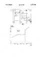
- FIG. 1 is a wiring diagram of the measurement circuit
- FIG. 2 shows the indication characteristic of the indicating instrument obtained with the circuit, namely the dial angle as a function of the temperature which is detected with an NTC-resistor.
- an NTC-resistor 1 is provided for measuring the temperature of cooling water.
- the resistor 1 serves as a measurement transmitter and is connected in series with an equivalent resistor 2 of an indicating instrument 3.
- the indicating instrument is constructed as a bimetallic indicating instrument.
- the base of the transistor 4 is controlled via a coupling resistor 6 from an output of a first difference amplifier 7.
- a positive input of the amplifier 7 of the difference amplifier 7 is connected via a decoupling resistor 8 to the NTC-resistor 1.
- a negative input is connected directly to the emitter of the transistor 4.
- the circuit is fed by a source of operating voltage which is connected to a terminal 9 and to ground.
- the above-described part of the circuit containing the first difference amplifier 7 operates in the manner that the voltage which drops at the emitter of the transistor 4 with respect to ground tracks the transmitter voltage at the NTC-resistor 1. If the equivalent resistor 2 is selected equal to the internal resistance of the indicating instrument 3, then a constant current therefore flows through the indicating instrument in the same way as through the equivalent resistor 2 and the NTC-resistor 1. This means that in a first measurement range, which extends up to 80° C. in FIG. 2, deflection of a pointer of the instrument 3 takes place in the same manner as though the indicating instrument 3 were connected in the customary manner in series with the NTC-resistor 1.
- a second difference amplifier 10 is connected in the part of the circuit described above.
- the second difference amplifier 10 normally receives at its positive input a reference voltage which corresponds to the divider ratio of series-connected resistors 11 and 12. At a negative input of the second difference amplifier 10 there is present the tracking voltage produced by the first difference amplifier 7 and the transistor 4.
- the divider ratio of the resistors 11 and 12 is so adjusted that the voltage at the positive input of the second difference amplifier 10 is equal to the tracking voltage at the emitter of the transistor 4 if the temperature of 80° C. is reached and exceeded at the NTC-resistor. Upon the exceeding of this temperature, the tracking voltage at the negative input of the second difference amplfiier 10 becomes smaller than the reference voltage at the positive input thereof. Via a diode 13 which is now acted on in forward direction, the output voltage of the second difference amplifier 10 is imparted to the positive input of the first difference amplifier 7.
- This part comprises essentially a third difference amplifier 14 whose output is connected, via a second diode 15, also to the positive input of the second difference amplifier 10. Furthermore the output of amplifier 14 is fed back via a resistor 16 to the positive input of the third difference amplifier 14.
- a voltage divider with resistors 17, 18 produces, by division of the operating voltage, a comparison voltage at a negative input of the third difference amplifier 14.
- the positive input of the third difference amplifier 14 is acted on, via a second decoupling resistor 19, by the transmitter voltage on the NTC-resistor 1, even if the clamping voltage acts on the circuit part containing the first difference amplifier 7.
- the potential at the output of the third difference amplifier 14 becomes approximately zero and the diode 15 conducts, the potential at the positive terminal of the second difference amplifier 10 also dropping to approximately zero.
- the potential at the output of the second difference amplifier drops in such a manner that the diode 13 blocks, i.e. the clamping voltage disappears.
- the part of the circuit containing the first difference amplifier 9 again operates uninfluenced, as described above. This means that the voltage at the indicating instrument increases suddenly to the value at which it tracks the transmitter voltage as if no clamping voltage were present.
- the tracking of the voltage at the indicating instrument 3 takes place in a manner unaffected by the clamping voltage as long as the temperature remains in the upper measurement range above 105° C.
Landscapes
- Physics & Mathematics (AREA)
- General Physics & Mathematics (AREA)
- Nonlinear Science (AREA)
- Indication And Recording Devices For Special Purposes And Tariff Metering Devices (AREA)
- Arrangements For Transmission Of Measured Signals (AREA)
- Measuring Temperature Or Quantity Of Heat (AREA)
- Measuring Instrument Details And Bridges, And Automatic Balancing Devices (AREA)
Abstract
Description
Claims (6)
Applications Claiming Priority (2)
| Application Number | Priority Date | Filing Date | Title |
|---|---|---|---|
| DE19853524886 DE3524886A1 (en) | 1985-07-12 | 1985-07-12 | MEASURING CIRCUIT ARRANGEMENT FOR AN ELECTRICAL PROCESSOR |
| DE3524886 | 1985-07-12 |
Publications (1)
| Publication Number | Publication Date |
|---|---|
| US4737786A true US4737786A (en) | 1988-04-12 |
Family
ID=6275578
Family Applications (1)
| Application Number | Title | Priority Date | Filing Date |
|---|---|---|---|
| US06/879,643 Expired - Fee Related US4737786A (en) | 1985-07-12 | 1986-06-27 | Measurement circuit suppressing variations in a display using an electric measurement transmitter |
Country Status (4)
| Country | Link |
|---|---|
| US (1) | US4737786A (en) |
| EP (1) | EP0212156B1 (en) |
| JP (1) | JPS6215411A (en) |
| DE (2) | DE3524886A1 (en) |
Families Citing this family (3)
| Publication number | Priority date | Publication date | Assignee | Title |
|---|---|---|---|---|
| JPH0199943A (en) * | 1987-09-30 | 1989-04-18 | Teraoka Seiko Co Ltd | Label printing and attaching apparatus |
| JPH0624331Y2 (en) * | 1988-07-07 | 1994-06-29 | 大阪機工株式会社 | Automatic label machine |
| CN110567596B (en) * | 2019-09-19 | 2021-06-18 | 中国第一汽车股份有限公司 | Pointer type water temperature meter indication method |
Citations (3)
| Publication number | Priority date | Publication date | Assignee | Title |
|---|---|---|---|---|
| US3927571A (en) * | 1974-01-18 | 1975-12-23 | Hobart Corp | Temperature indicating device |
| US4575711A (en) * | 1982-09-24 | 1986-03-11 | Nittan Company, Limited | Alarm terminal device |
| US4638304A (en) * | 1983-12-13 | 1987-01-20 | Nittan Co., Ltd. | Environmental abnormality detecting apparatus |
Family Cites Families (3)
| Publication number | Priority date | Publication date | Assignee | Title |
|---|---|---|---|---|
| US3390332A (en) * | 1964-02-17 | 1968-06-25 | Weston Instruments Inc | Suppressed scale electrical instrument with adjustable auxiliary spring means |
| DE2452529C3 (en) * | 1974-11-06 | 1979-12-13 | Satchwell-Birka Regelungstechnik Gmbh, 5630 Remscheid | Device for the independent setting of the start and end values of an electrical measuring range with a bridge circuit |
| GB1578535A (en) * | 1976-06-24 | 1980-11-05 | Smiths Industries Ltd | Display systems for displaying measurements |
-
1985
- 1985-07-12 DE DE19853524886 patent/DE3524886A1/en not_active Withdrawn
-
1986
- 1986-06-27 US US06/879,643 patent/US4737786A/en not_active Expired - Fee Related
- 1986-06-30 EP EP86108868A patent/EP0212156B1/en not_active Expired - Lifetime
- 1986-06-30 DE DE8686108868T patent/DE3680257D1/en not_active Expired - Lifetime
- 1986-07-10 JP JP61160992A patent/JPS6215411A/en active Pending
Patent Citations (3)
| Publication number | Priority date | Publication date | Assignee | Title |
|---|---|---|---|---|
| US3927571A (en) * | 1974-01-18 | 1975-12-23 | Hobart Corp | Temperature indicating device |
| US4575711A (en) * | 1982-09-24 | 1986-03-11 | Nittan Company, Limited | Alarm terminal device |
| US4638304A (en) * | 1983-12-13 | 1987-01-20 | Nittan Co., Ltd. | Environmental abnormality detecting apparatus |
Also Published As
| Publication number | Publication date |
|---|---|
| JPS6215411A (en) | 1987-01-23 |
| DE3680257D1 (en) | 1991-08-22 |
| EP0212156A2 (en) | 1987-03-04 |
| EP0212156A3 (en) | 1988-10-05 |
| EP0212156B1 (en) | 1991-07-17 |
| DE3524886A1 (en) | 1987-01-22 |
Similar Documents
| Publication | Publication Date | Title |
|---|---|---|
| US5656771A (en) | Motor vehicle cooling system status indicator | |
| US4513277A (en) | Low fuel indicator system | |
| GB2136579A (en) | Thermal anemometer | |
| US3938117A (en) | Critical liquid-level warning circuit | |
| US4737786A (en) | Measurement circuit suppressing variations in a display using an electric measurement transmitter | |
| US4078531A (en) | Exhaust temperature monitoring system | |
| US3829849A (en) | Means for providing thermocouple failure detection in a multiple probe system | |
| US4228684A (en) | Remote temperature measuring system with semiconductor junction sensor | |
| US5483109A (en) | Anti-fuel slosh circuit | |
| US4656464A (en) | Liquid level detector | |
| US4868508A (en) | Trouble detecting circuit for resistive sensor type indicator | |
| JPS59182318A (en) | Measuring device | |
| US3886518A (en) | Critical liquid-level warning circuit | |
| US10778096B2 (en) | Current detection circuit and power supply device | |
| US20060001567A1 (en) | Sensor with improved voltage protection | |
| US4903011A (en) | Lamp drive circuit | |
| US5698974A (en) | Robust gauge driving circuit with pulse modulated input | |
| US3835313A (en) | Arrangement for compensating for changes in the operating characteristics of a measuring element | |
| JPH05312619A (en) | Oil level detector | |
| US3622975A (en) | Engine temperature-indicating apparatus | |
| EP0398509B1 (en) | Monitoring circuit | |
| US4188623A (en) | Temperature responsive apparatus employing a thermocouple | |
| EP0399678A1 (en) | Control circuit for electrical gauge | |
| US5381102A (en) | Device with a current divider for controlling adjustment of signals from sensors | |
| US7714586B2 (en) | Control unit and control device comprising the control unit |
Legal Events
| Date | Code | Title | Description |
|---|---|---|---|
| AS | Assignment |
Owner name: VDO ADOLF SCHINDLING AG, GRAFSTRASSE 103, 6000 FRA Free format text: ASSIGNMENT OF ASSIGNORS INTEREST.;ASSIGNOR:VON PENTZ, BERNHARD;REEL/FRAME:004658/0863 Effective date: 19861219 Owner name: VDO ADOLF SCHINDLING AG, A CORP. OF GERMANY,GERMAN Free format text: ASSIGNMENT OF ASSIGNORS INTEREST;ASSIGNOR:VON PENTZ, BERNHARD;REEL/FRAME:004658/0863 Effective date: 19861219 Owner name: VDO ADOLF SCHINDLING AG, GERMANY Free format text: ASSIGNMENT OF ASSIGNORS INTEREST;ASSIGNOR:VON PENTZ, BERNHARD;REEL/FRAME:004658/0863 Effective date: 19861219 |
|
| FPAY | Fee payment |
Year of fee payment: 4 |
|
| REMI | Maintenance fee reminder mailed | ||
| LAPS | Lapse for failure to pay maintenance fees | ||
| FP | Expired due to failure to pay maintenance fee |
Effective date: 19960417 |
|
| STCH | Information on status: patent discontinuation |
Free format text: PATENT EXPIRED DUE TO NONPAYMENT OF MAINTENANCE FEES UNDER 37 CFR 1.362 |