US473538A - Electrical measuring instrument - Google Patents
Electrical measuring instrument Download PDFInfo
- Publication number
- US473538A US473538A US473538DA US473538A US 473538 A US473538 A US 473538A US 473538D A US473538D A US 473538DA US 473538 A US473538 A US 473538A
- Authority
- US
- United States
- Prior art keywords
- scale
- plate
- case
- electrical measuring
- measuring instrument
- Prior art date
- Legal status (The legal status is an assumption and is not a legal conclusion. Google has not performed a legal analysis and makes no representation as to the accuracy of the status listed.)
- Expired - Lifetime
Links
- 239000011521 glass Substances 0.000 description 9
- 239000000463 material Substances 0.000 description 5
- 238000010276 construction Methods 0.000 description 2
- 239000012780 transparent material Substances 0.000 description 2
- 241000669003 Aspidiotus destructor Species 0.000 description 1
- 239000000428 dust Substances 0.000 description 1
- 230000005611 electricity Effects 0.000 description 1
- 239000005337 ground glass Substances 0.000 description 1
- 238000005286 illumination Methods 0.000 description 1
- 238000005259 measurement Methods 0.000 description 1
- 239000002184 metal Substances 0.000 description 1
Images
Classifications
-
- G—PHYSICS
- G01—MEASURING; TESTING
- G01R—MEASURING ELECTRIC VARIABLES; MEASURING MAGNETIC VARIABLES
- G01R19/00—Arrangements for measuring currents or voltages or for indicating presence or sign thereof
- G01R19/145—Indicating the presence of current or voltage
- G01R19/155—Indicating the presence of voltage
Definitions
- My invention relates to an instrument for measurement of differences of potential in electric current; and it consists more particu larly in the construction and arrangement of the indicating device, in which the scale-plate is made of a translucent material, so that it may be illuminated by a light placed behind it, and thus rendered visible at a considerable distance from the apparatus.
- My invention further consists in a box or case inclosing the index or pointer, having one of its walls formed of translucent material, on which the scale is inscribed, the said scale being visible through an opening in the opposite wall of the case, which is closed with a plate of glass.
- the accompanying drawing is a vertical section of an electrical measuring instrument with which my device is embodied.
- A is a box or case receiving the cylindrical shell 13, which incloses the coil 0.
- D and E are pole-pieces of the electro-magnet so formed.
- 1 is a cylinder of light metal, which is surrounded by a coil G.
- a rod J which passes up through jeweled guides K L in the opening M in the pole-piece E.
- a forked piece N which connects with the horizontal arm of the bell-crank lever O.
- the other arm of said lever is pivoted to a link P, to which is secured one end of the spiral spring R.
- the other end of said spiral spring is fastened to a short threaded rod, which is received in the collar Q.
- Another spiral spring S is provided with a threaded rod, which also enters the collar Q and is fastened at its other extremity by a nut, as shown, to the wall of the case A. Supported on the collar Q and extending vertically upward is the counterweighted index-needle T.
- the operation of the instrument is as follows: hen the current, the potential of which is to be measured, is passed through the coils O and G, the cylinder F is moved upward or downward and its motion is transmitted through the links and bell-crank lever to the springs R S. The springs then rotate, carrying with them the sleeve R and causing the needle T to move in front of the scale. By reason of the illumination of the scale the movement of the index-needle may easily be perceived and is visible from a considerable distance.
- I may vary the before-described construction of the scale-plate in various ways.
- I may use a scale-plate of semi-translucent materialsuch as ground glassin one wall and a plate of clear glass in the other, or instead of inscribing the scale-marking on the ground-glass plate I may inscribe it on the clear-glass plate, or I may use two plates of clear glass, or I may make both plates semiopaque and recognize the position of the needle by its shadow on one plate viewed from the exterior, in which case the scale-marking will be on the outside plate.
- box or case A of the instrument incloses both the working mechanism and the needle hermetically, so that although it is necessary to bring the needle outside of the main case in order to provide for the transparent scale and the arrangement of the light behind it, yet, nevertheless, the hermetically-sealed case prevents any possible ingress of dust to the mechanism.
- an index or needle actuated by said mechanism, a box or case wholly inclosing said index and inserted in one of the walls of said case, a plate of translucent material inscribed with a scale-marking appropriate to the instrument, over which scale said index moves, and in the opposite wall a plate of glass or other-transparent material.
- a box or case hermetically inclosing both said index and said mechanism and inserted in one of the walls of said case, a plate of translucent material inscribed with a scalemarking appropriate to the instrument, over which scale said index moves, and in the opposite wall a plate of glass or other transparent material.
Landscapes
- Physics & Mathematics (AREA)
- General Physics & Mathematics (AREA)
- Measurement Of Unknown Time Intervals (AREA)
Description
(NoModeL) E. WESTON. ELECTRICAL MEASURIIIG INSTRUMENT. No. 473,538.
Patented Apr. 26, 1892.
IIIIIII INVENTOI? d4uaiwb 3.557%
ATTORNEY.
? WIT/158.95%? @0210 UNITED STATES PATENT @rricn.
EDlVARD WESTON, OF NElVARK, NEIV JERSEY.
ELECTRICAL M EASU RING IN STRUM'ENT.
SPECIFICATION forming part of Letters Patent No. 473,538, dated. April 26, 1892.
Application filed January 8, 1891. Serial No. 377,088. (No model.)
To aZZ whom it may concern.-
Be it known that I, EDWARD WEsToN, of Newark, Essex county, New Jersey, have i11- vented a new and useful Improvementin Electrical Measuring Instruments, of which the following is a specification.
My invention relates to an instrument for measurement of differences of potential in electric current; and it consists more particu larly in the construction and arrangement of the indicating device, in which the scale-plate is made of a translucent material, so that it may be illuminated by a light placed behind it, and thus rendered visible at a considerable distance from the apparatus.
My invention further consists in a box or case inclosing the index or pointer, having one of its walls formed of translucent material, on which the scale is inscribed, the said scale being visible through an opening in the opposite wall of the case, which is closed with a plate of glass.
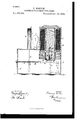
The accompanying drawing is a vertical section of an electrical measuring instrument with which my device is embodied.
A is a box or case receiving the cylindrical shell 13, which incloses the coil 0.
D and E are pole-pieces of the electro-magnet so formed.
1 is a cylinder of light metal, which is surrounded by a coil G.
Connected to the cylinder-head H is a rod J, which passes up through jeweled guides K L in the opening M in the pole-piece E. Pivoted also to the cylinderhead H is a forked piece N, which connects with the horizontal arm of the bell-crank lever O. The other arm of said lever is pivoted to a link P, to which is secured one end of the spiral spring R. The other end of said spiral spring is fastened to a short threaded rod, which is received in the collar Q. Another spiral spring S is provided with a threaded rod, which also enters the collar Q and is fastened at its other extremity by a nut, as shown, to the wall of the case A. Supported on the collar Q and extending vertically upward is the counterweighted index-needle T.
In the cover U of the case A there is an opening, through which the needle T extends, and above this opening there is a circular frame V, in which are set two plates of glass IV and X. On one of these plates of glass X is inscribed the scale-marking, and this plate of glass is ground or made partly translucent. Placed between the caseU and the inclosing cylinder 13 is an incandescent electric lamp Y, which serves to illuminate the translucent scale-plate X.. This lamp is connected with any independent source of electricity. The coils C and G are connected in series.
The operation of the instrument is as follows: hen the current, the potential of which is to be measured, is passed through the coils O and G, the cylinder F is moved upward or downward and its motion is transmitted through the links and bell-crank lever to the springs R S. The springs then rotate, carrying with them the sleeve R and causing the needle T to move in front of the scale. By reason of the illumination of the scale the movement of the index-needle may easily be perceived and is visible from a considerable distance.
I may vary the before-described construction of the scale-plate in various ways. Thus I may use a scale-plate of semi-translucent materialsuch as ground glassin one wall and a plate of clear glass in the other, or instead of inscribing the scale-marking on the ground-glass plate I may inscribe it on the clear-glass plate, or I may use two plates of clear glass, or I may make both plates semiopaque and recognize the position of the needle by its shadow on one plate viewed from the exterior, in which case the scale-marking will be on the outside plate.
It will be apparent from the preceding that the box or case A of the instrument incloses both the working mechanism and the needle hermetically, so that although it is necessary to bring the needle outside of the main case in order to provide for the transparent scale and the arrangement of the light behind it, yet, nevertheless, the hermetically-sealed case prevents any possible ingress of dust to the mechanism.
1. In combination with the working mechanism of an electrical measuring instrument, an index or needle actuated by said mechanism, abox or case wholly inclosing said index and inserted in one of the walls of said case, and a plate of translucent material inscribed with a scale-marking appropriate to the instrument, over which scale said index moves. 2. In combination with the working mechanism of an electrical measuring instrument,-
an index or needle actuated by said mechanism, a box or case wholly inclosing said index and inserted in one of the walls of said case, a plate of translucent material inscribed with a scale-marking appropriate to the instrument, over which scale said index moves, and in the opposite wall a plate of glass or other-transparent material.
3. In combination with the working mechanism of an electrical measuring instrument, an index or needle actuated by said mechanism, a box or case hermetically inclosing both said index and said mechanism and inserted in one of the walls of said case, a plate of translucent material inscribed with a scalemarking appropriate to the instrument, over which scale said index moves, and in the opposite wall a plate of glass or other transparent material.
4. In combination with the standard of an 7 electrical measuring instrument, the case U, containing the translucent dial X, the movable needle fl, and the electric lamp Y, supported in rear of said dial and transmitting light through the same.
EDWARD WESTON. Y Witnesses:
M. Boson, JAMES .T. LAW.
Publications (1)
| Publication Number | Publication Date |
|---|---|
| US473538A true US473538A (en) | 1892-04-26 |
Family
ID=2542397
Family Applications (1)
| Application Number | Title | Priority Date | Filing Date |
|---|---|---|---|
| US473538D Expired - Lifetime US473538A (en) | Electrical measuring instrument |
Country Status (1)
| Country | Link |
|---|---|
| US (1) | US473538A (en) |
Cited By (5)
| Publication number | Priority date | Publication date | Assignee | Title |
|---|---|---|---|---|
| US2502419A (en) * | 1945-02-03 | 1950-04-04 | Western Union Telegraph Co | Electrically actuated recording unit |
| US2791394A (en) * | 1952-08-18 | 1957-05-07 | Milwaukee Gas Specialty Co | Control device for fluid fuel burning apparatus and the like |
| US2932776A (en) * | 1956-02-16 | 1960-04-12 | Cohu Electronics Inc | Direct recording oscillograph |
| US3525963A (en) * | 1968-07-25 | 1970-08-25 | English Electric Co Ltd | Electro-magnetic actuator with armature assembly slidable between two limit positions |
| US4236130A (en) * | 1978-09-25 | 1980-11-25 | Gustav Hubert | Solenoid actuator having a long stroke |
-
0
- US US473538D patent/US473538A/en not_active Expired - Lifetime
Cited By (5)
| Publication number | Priority date | Publication date | Assignee | Title |
|---|---|---|---|---|
| US2502419A (en) * | 1945-02-03 | 1950-04-04 | Western Union Telegraph Co | Electrically actuated recording unit |
| US2791394A (en) * | 1952-08-18 | 1957-05-07 | Milwaukee Gas Specialty Co | Control device for fluid fuel burning apparatus and the like |
| US2932776A (en) * | 1956-02-16 | 1960-04-12 | Cohu Electronics Inc | Direct recording oscillograph |
| US3525963A (en) * | 1968-07-25 | 1970-08-25 | English Electric Co Ltd | Electro-magnetic actuator with armature assembly slidable between two limit positions |
| US4236130A (en) * | 1978-09-25 | 1980-11-25 | Gustav Hubert | Solenoid actuator having a long stroke |
Similar Documents
| Publication | Publication Date | Title |
|---|---|---|
| US473538A (en) | Electrical measuring instrument | |
| US1357731A (en) | Weight-indicator for scales | |
| US2085224A (en) | Recording meter | |
| US1244634A (en) | Electrical attachment for reading meters. | |
| US4141247A (en) | Optical warning indicator means on bimetal measuring element | |
| US1728929A (en) | Combustion indicator | |
| US1899804A (en) | Line image producer | |
| US3590261A (en) | Optoelectric transducers which utilize a single light source to produce both analog and digital outputs | |
| US1488818A (en) | Indicating device for measuring instruments | |
| US1742229A (en) | Predetermined-weight-indicating device for scales | |
| US1287896A (en) | Illuminated weighing-scale. | |
| US2331475A (en) | Photoelectric control device | |
| US1619121A (en) | Computing scale | |
| US1743852A (en) | Meter | |
| US2312716A (en) | Unitfd statfs patfnt offtpf | |
| US2275344A (en) | Measuring instrument, particularly an exposure meter | |
| US2425595A (en) | Supporting means for the moving elements of electrical indicating instruments | |
| US266244A (en) | Edward weston | |
| US1181226A (en) | Indicator. | |
| US3529897A (en) | Indicating mechanism for zero-current instruments | |
| US418889A (en) | Alfred j | |
| SU976383A1 (en) | Electric instrument | |
| RU2389989C1 (en) | SIGNALLING AND EXPLOSION-PROOF MANOMETRE DM 5010 CrOEx | |
| US362957A (en) | haig-ht | |
| US335687A (en) | John i |