US4725035A - Apparatus for manufacture of sealing closures for a telecommunications cable splice - Google Patents
Apparatus for manufacture of sealing closures for a telecommunications cable splice Download PDFInfo
- Publication number
- US4725035A US4725035A US06/800,835 US80083585A US4725035A US 4725035 A US4725035 A US 4725035A US 80083585 A US80083585 A US 80083585A US 4725035 A US4725035 A US 4725035A
- Authority
- US
- United States
- Prior art keywords
- mold
- sealing
- sealing member
- cable
- low pressure
- Prior art date
- Legal status (The legal status is an assumption and is not a legal conclusion. Google has not performed a legal analysis and makes no representation as to the accuracy of the status listed.)
- Expired - Fee Related
Links
- 238000007789 sealing Methods 0.000 title claims abstract description 109
- 238000004519 manufacturing process Methods 0.000 title description 4
- 239000011248 coating agent Substances 0.000 claims abstract description 27
- 238000000576 coating method Methods 0.000 claims abstract description 27
- -1 polytetrafluorethylene Polymers 0.000 claims abstract description 7
- 239000003822 epoxy resin Substances 0.000 claims abstract description 4
- 229920000647 polyepoxide Polymers 0.000 claims abstract description 4
- 229920001343 polytetrafluoroethylene Polymers 0.000 claims abstract description 4
- 238000000465 moulding Methods 0.000 claims description 25
- 238000005538 encapsulation Methods 0.000 claims description 17
- 229910052751 metal Inorganic materials 0.000 claims description 10
- 239000002184 metal Substances 0.000 claims description 10
- 238000010276 construction Methods 0.000 claims description 7
- 230000002093 peripheral effect Effects 0.000 claims description 5
- 230000008859 change Effects 0.000 claims description 2
- 230000003014 reinforcing effect Effects 0.000 claims description 2
- 239000004033 plastic Substances 0.000 description 49
- 229920003023 plastic Polymers 0.000 description 49
- 239000000463 material Substances 0.000 description 19
- 239000004020 conductor Substances 0.000 description 17
- 238000000034 method Methods 0.000 description 14
- 239000007789 gas Substances 0.000 description 10
- 239000012768 molten material Substances 0.000 description 9
- 230000004048 modification Effects 0.000 description 7
- 238000012986 modification Methods 0.000 description 7
- 239000002991 molded plastic Substances 0.000 description 6
- 229910052782 aluminium Inorganic materials 0.000 description 5
- XAGFODPZIPBFFR-UHFFFAOYSA-N aluminium Chemical compound [Al] XAGFODPZIPBFFR-UHFFFAOYSA-N 0.000 description 5
- 238000001816 cooling Methods 0.000 description 5
- 229920000181 Ethylene propylene rubber Polymers 0.000 description 3
- 239000004698 Polyethylene Substances 0.000 description 3
- 229910000831 Steel Inorganic materials 0.000 description 3
- 229920000573 polyethylene Polymers 0.000 description 3
- 229920000915 polyvinyl chloride Polymers 0.000 description 3
- 239000004800 polyvinyl chloride Substances 0.000 description 3
- 230000008569 process Effects 0.000 description 3
- 239000010959 steel Substances 0.000 description 3
- 230000000295 complement effect Effects 0.000 description 2
- 230000000694 effects Effects 0.000 description 2
- 238000009413 insulation Methods 0.000 description 2
- 239000000047 product Substances 0.000 description 2
- 230000009471 action Effects 0.000 description 1
- 230000004323 axial length Effects 0.000 description 1
- 230000015572 biosynthetic process Effects 0.000 description 1
- 238000010961 commercial manufacture process Methods 0.000 description 1
- 230000006835 compression Effects 0.000 description 1
- 238000007906 compression Methods 0.000 description 1
- 239000012467 final product Substances 0.000 description 1
- 239000012530 fluid Substances 0.000 description 1
- LNEPOXFFQSENCJ-UHFFFAOYSA-N haloperidol Chemical compound C1CC(O)(C=2C=CC(Cl)=CC=2)CCN1CCCC(=O)C1=CC=C(F)C=C1 LNEPOXFFQSENCJ-UHFFFAOYSA-N 0.000 description 1
- 238000001746 injection moulding Methods 0.000 description 1
- 239000011810 insulating material Substances 0.000 description 1
- 239000012778 molding material Substances 0.000 description 1
- 229920001084 poly(chloroprene) Polymers 0.000 description 1
- 230000002265 prevention Effects 0.000 description 1
- 230000000717 retained effect Effects 0.000 description 1
- 238000007711 solidification Methods 0.000 description 1
- 230000008023 solidification Effects 0.000 description 1
- 230000008719 thickening Effects 0.000 description 1
- 238000004804 winding Methods 0.000 description 1
Images


Classifications
-
- B—PERFORMING OPERATIONS; TRANSPORTING
- B29—WORKING OF PLASTICS; WORKING OF SUBSTANCES IN A PLASTIC STATE IN GENERAL
- B29C—SHAPING OR JOINING OF PLASTICS; SHAPING OF MATERIAL IN A PLASTIC STATE, NOT OTHERWISE PROVIDED FOR; AFTER-TREATMENT OF THE SHAPED PRODUCTS, e.g. REPAIRING
- B29C70/00—Shaping composites, i.e. plastics material comprising reinforcements, fillers or preformed parts, e.g. inserts
- B29C70/68—Shaping composites, i.e. plastics material comprising reinforcements, fillers or preformed parts, e.g. inserts by incorporating or moulding on preformed parts, e.g. inserts or layers, e.g. foam blocks
- B29C70/74—Moulding material on a relatively small portion of the preformed part, e.g. outsert moulding
-
- B—PERFORMING OPERATIONS; TRANSPORTING
- B29—WORKING OF PLASTICS; WORKING OF SUBSTANCES IN A PLASTIC STATE IN GENERAL
- B29C—SHAPING OR JOINING OF PLASTICS; SHAPING OF MATERIAL IN A PLASTIC STATE, NOT OTHERWISE PROVIDED FOR; AFTER-TREATMENT OF THE SHAPED PRODUCTS, e.g. REPAIRING
- B29C33/00—Moulds or cores; Details thereof or accessories therefor
- B29C33/0011—Moulds or cores; Details thereof or accessories therefor thin-walled moulds
-
- B—PERFORMING OPERATIONS; TRANSPORTING
- B29—WORKING OF PLASTICS; WORKING OF SUBSTANCES IN A PLASTIC STATE IN GENERAL
- B29C—SHAPING OR JOINING OF PLASTICS; SHAPING OF MATERIAL IN A PLASTIC STATE, NOT OTHERWISE PROVIDED FOR; AFTER-TREATMENT OF THE SHAPED PRODUCTS, e.g. REPAIRING
- B29C33/00—Moulds or cores; Details thereof or accessories therefor
- B29C33/0038—Moulds or cores; Details thereof or accessories therefor with sealing means or the like
-
- H—ELECTRICITY
- H02—GENERATION; CONVERSION OR DISTRIBUTION OF ELECTRIC POWER
- H02G—INSTALLATION OF ELECTRIC CABLES OR LINES, OR OF COMBINED OPTICAL AND ELECTRIC CABLES OR LINES
- H02G1/00—Methods or apparatus specially adapted for installing, maintaining, repairing or dismantling electric cables or lines
- H02G1/14—Methods or apparatus specially adapted for installing, maintaining, repairing or dismantling electric cables or lines for joining or terminating cables
- H02G1/145—Moulds
-
- Y—GENERAL TAGGING OF NEW TECHNOLOGICAL DEVELOPMENTS; GENERAL TAGGING OF CROSS-SECTIONAL TECHNOLOGIES SPANNING OVER SEVERAL SECTIONS OF THE IPC; TECHNICAL SUBJECTS COVERED BY FORMER USPC CROSS-REFERENCE ART COLLECTIONS [XRACs] AND DIGESTS
- Y10—TECHNICAL SUBJECTS COVERED BY FORMER USPC
- Y10S—TECHNICAL SUBJECTS COVERED BY FORMER USPC CROSS-REFERENCE ART COLLECTIONS [XRACs] AND DIGESTS
- Y10S277/00—Seal for a joint or juncture
- Y10S277/91—O-ring seal
Definitions
- This invention relates to the manufacture of sealing closures for telecommunications cable splices.
- Such branch cables may be in the form of drop wires for connection to customers' premises or cables having fewer pairs of conductors than the main cable and provided for connecting telephone equipment in a localized area with the main cable.
- the cables need to be opened for any splicing operation between conductors and, subsequent to the splicing operation, it is necessary to seal the spliced region from ambient atmosphere to prevent moisture from contacting the spliced conductors.
- One effective method of sealing spliced together conductors is as described in U.S. Pat. No.
- a spliced region between two cables in a gas pressurizable cable system comprises two molded plastic ends which intimately surround end portions of cable sections, one at each side of the splice region and a bridging means to form, with the plastic ends, a sealed chamber which contains the spliced together conductors and which may be gas pressurized.
- each plastic end is of circular cross-section with a peripheral groove housing a sealing member which seals against the inner surface of a cylindrical member forming the bridging means.
- a sealing member which seals against the inner surface of a cylindrical member forming the bridging means.
- the surface of the groove it is essential for the surface of the groove to be as smooth as possible. In high pressure molding techniques of plastic parts, excellent surface finish is automatically obtained by the flow of molten material quickly and under high pressure into intimate contact with the mold surfaces.
- the present invention provides a low pressure mold which is constructed so as to avoid the above problems.
- a low pressure mold comprising metal mold parts having surfaces which, in an assembly of the parts, form a mold cavity, said surfaces having a thermally insulating coating of from 0.005 inches to 0.050 inches thick.
- the heat transfer through the insulating coating and into the metal mold parts is such as to ensure that when the molten material contacts the insulating coating, it cools at such a slow rate to allow for it to move into intimate contact with the mold surface.
- the insulating coating is sufficiently thin that it does not retain heat unduly, but transfers it at an acceptable rate to the metal mold parts which act as a heat sink. It follows that where a surface of a molded article is required as a sealing surface, then the mold cavity surface formed by the insulating coating is substantially smooth and provides a substantially smooth sealing surface to the article.
- the slowing down in heat transfer is sufficient to provide the required smooth surfaces by low pressure molding techniques while the cooling rate is commercially acceptable. A thicker coating will cause a slower cooling effect, but this is acceptable within the range according to the invention.
- the maximum thickness of the insulating coating is 0.020 inches. With such a thickness it has been found that heat transfer is sufficiently rapid to make the commercial manufacture of plastic ends for a closure of a splice region an attractive proposition.
- the insulating coating may be of any suitable material to provide the required heat transfer while also delaying the cooling of the molten material sufficiently to ensure that it flows into intimate contact with the mold surfaces.
- coating materials are epoxy resins, polytetrafluorethylene and polyvinylchloride which may be provided upon the mold surface in strip form.
- Such an encapsulation may be in the form of molded plastic ends, as discussed above, or may be in the form of a complete molded plastic encapsulation which enshrouds the splice region of a cable. In either case, the molding of the encapsulation requires the use of end seals, one at each end of the mold and surrounding the cable.
- a single mold may be used for many sizes of cable or for many combinations of numbers and sizes of cables used in the splice arrangement.
- a normal seal may be used effectively for one cable size only and hence a large number of seals may need to be used for different cable sizes.
- the quantity of required seals in the field increases also because of the numbers of cables which may be used in a splice arrangement and which may together be surrounded by a single closure. If such a large amount of seals is to be carried by a molding operator in the field, then this would involve the transportation of many items of equipment. The use of such a large amount of seals for different sized cables and different combinations of cables adds unduly to the complete inventory of the molding equipment much of which is necessarily carried manually.
- the present invention is concerned with a sealing member that when used with a complementary sealing member provides a seal which is suitable for sealing around cables of different diameters or around different numbers of cables and ranges of diameters.
- a limited number of sealing members according to the invention are required to seal around telecommunications cables of diverse diameters and numbers in a splice region.
- the present invention further provides a sealing member comprising a body having a peripheral surface with a plurality of surface regions which are relatively disposed in series around the body, each surface region formed with a respective sealing surface configuration comprising at least one substantially semi-circular, resiliently flexible, sealing surface with the sealing surface configuration being different from one surface region to another.
- the sealing surface configuration may differ from one surface region to another by virtue of different sizes or arrangements of the semi-circular sealing surfaces.
- Such a sealing member when used with a complementary sealing member, provides different diameter sealing surfaces for sealing against different diameters of cable or alternatively provides different arrangements of seals, i.e. for sealing upon one or more cables at one end of a mold.
- the invention also includes a low pressure mold comprising two mold halves which when assembled together define a cavity for molding an encapsulation around a splice region of a telecommunications cable, the assembled mold having ends which define an opening for passage of the cable from the cavity and the mold ends defined by ends of the mold halves; a plurality of sealing members, one for each mold half at each end of the mold, each sealing member comprising a peripheral surface with a plurality of surface regions which are relatively disposed in series around a body of the sealing member, each surface region formed with a respective sealing surface configuration comprising at least one substantially semi-circular, resiliently flexible, sealing surface with the sealing surface configuration being different from one surface region to another; and means for mounting each sealing member upon its respective mold half so that an surface region is in an operating position in which it cooperates with a corresponding surface region of an associated sealing member of the other mold half to seal around a cable extending into the mold, and in respect of each sealing member, said means permits change in position of the sealing member selectively to locate any associated pair of
- each sealing member is disposed at equal distances from a common center and the sealing member is attached at the common center to its associated mold half.
- each sealing member may be rotated about its center to dispose any desired surface region in opposition to the associated surface region of the associated sealing member across the parting line of the mold.
- each sealing member is held at more than one position and may be removed and replaced in a different position for disposing the desired surface in its operating position.
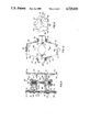
- FIG. 1 is a side elevational view, partly in cross-section of a gas pressurizable closure surrounding a splice region of cable;
- FIG. 2 is a view on the end of the closure taken in cross-section through the cable along line II--II in FIG. 1;
- FIG. 3 is a cross-sectional view taken along line III--III in FIG. 1 of part of the closure to show a detail;
- FIG. 4 is a top view in the direction of arrow IV in FIG. 3;
- FIG. 5 is a view in the direction of arrow V in FIG. 1;
- FIG. 6 is a cross-sectional view through a molded plastic end of the closure
- FIG. 7 is a view similar to FIG. 1 of a modification of the embodiment
- FIG. 8 is an end view of an end of the closure of the modification taken in cross-section through the cable along line VIII--VIII;
- FIG. 9 is a cross-sectional view through a mold used for molding a plastic end during the making of the closure of FIG. 1;
- FIG. 10 is a view of the mold in the direction of arrow X in FIG. 9 and with end seals removed for clarity;
- FIG. 11 is a plan view of a sealing member used as part of a seal for sealing the ends of the mold
- FIG. 12 is a view similar to FIG. 10 and showing the sealing members in position for molding a plastic end around the cable to provide the construction shown in FIG. 1;
- FIG. 13 is a view similar to FIG. 12 with the sealing members adjusted in position and for making a plastic end according to the modification shown in FIGS. 6 and 7;
- FIG. 14 shows the assembly of the molds in spaced-apart positions upon a cable during molding of the end caps
- FIG. 15 is a plan view of part of a rigid mold locking bar holding the molds in aligned positions.
- FIG. 16 is a view of part of the locking bar in the direction of arrow XVI in FIG. 14.
- two end sections 10 and 12 of pressurizable cables have their conductors 14 and 16 extending outwardly beyond the ends of the cable jackets and sheaths.
- Each conductor of one cable is connected to a conductor of the other cable to form a splice 18.
- Each splice and any bare conductor ends leading to it are electrically isolated from other splices in conventional fashion with insulating wrapping material.
- the splice region 20 formed along the axial lengths of the cables by the splices 18 is provided with a gas pressurizable closure 22.
- the closure 22 comprises two molded plastic ends 24 which are spaced-apart one at each axial side of the splice region and surround the cable end sections 10 and 12.
- the closure also includes a shroud means 26 which is formed into substantially cylindrical condition from a flexible sheet material such as steel which is wrapped around the two plastic ends to form a sleeve.
- the sleeve is sealed to each of the plastic ends 24 and the closure 22 is generally of a construction such as is described in U.S. patent application Ser. No. 648,461 filed Sept. 7, 1984 and entitled “Cable Encapsulation And Strain Relief" in the name of L. J. Charlebois (Canadian application No. 462,241 filed Aug. 31, 1984).
- each plastic end 24 has a main or large diameter disc-shaped section 28.
- This section 28 has an annular groove 30 within which is disposed a compressible plastic seal 32 which is also sealed against the inside surface of the shroud means 26.
- Extending from each side of the section 28 is an axial extension 34 which, as is clear from FIGS. 1, 2 and 5 is of oval or elliptical shape in axial view for reasons to be discussed.
- the two plastic ends 24 are connected together by two tensile strength members 36 (see particularly FIG. 5) which are either steel bars or tubes extending between and screw-threadedly connected to screw-threaded studs 38 which are molded integrally with the inwardly facing extensions 34 and extend therefrom for securing to the bars 36.
- the tensile members 36 and studs 38 are omitted from FIG. 1 to show the cable end sections in more detail.
- the bars and studs act to ensure that tensile loads such as are produced in the cable do not cause the cables and thus the plastic ends to pull apart. As discussed in the latter mentioned application, such an arrangement is particularly useful in the case of aerial cable.
- the sheet forming the shroud means 26 has side edges 40 which are bent to form a U-shape as shown in FIG. 3, and the bases of the two U-shapes oppose each other and hold between them two axially extending seals 42 for fluid tightly sealing the confronting edges of the sheets.
- arms 44 of each U-shape increase in length from one end of the sleeve towards the center of the closure and metal locking devices 46 are provided of C-shaped cross-section and also of tapering shape as shown by FIG. 4.
- Each device 46 conforms to the combined shape of the opposing arms 44 and is mounted upon the side edges 40 from an end of the sleeve as shown by FIG. 4, so as to interlock with the U-shaped configuration.
- each plastic end 24 is provided with a strain relief device which is in series with the bars 36 in transferring tensile loads from one cable to the other.
- This strain relief device comprises a strap member 50 which is bent around each of the cable end sections 10 and 12 and has flanges 52 upstanding from a base 54 which contacts the cable.
- Each of the bases is formed with a piercing means in the form of prongs (not shown) which project into the cable jacket to hold the base in position as the plastic ends are molded in position, the flanges then becoming embedded in the material of the encapsulations formed by the plastic ends.
- a piercing means in the form of prongs (not shown) which project into the cable jacket to hold the base in position as the plastic ends are molded in position, the flanges then becoming embedded in the material of the encapsulations formed by the plastic ends.
- each of the plastic ends 24 there is disposed a seal arrangement to prevent pressurized air from escaping from the chamber 50 along the interfacial region between the associated cable and the plastic end.
- This seal acts effectively to seal between the jacket surface and the plastic end in a case where a single jacket is provided upon a cable.
- each cable is formed with two jackets 58 and 60, one disposed within the other.
- it is also necessary to prevent the air from escaping along the cable itself, i.e. along the outside surface of the inner jacket 60 at its interface with any surrounding layer of material. To provide the effective seal, therefore, and as shown by FIG.
- the outer jacket 58 is removed for a further distance along each of the cables so that the inner jacket 60 projects further towards the splice region.
- the end 62 of the jacket 58 terminates within the plastic end and a seal 64 is provided around each of the jackets 58 and 60.
- Each seal is of a construction described in U.S. patent application No. 648,460 filed Sept. 7, 1984 (Canadian application No. 462,242) and entitled "Sealing Closure For A Cable Splice" in the names of L. J. Charlebois and K. H. Dick.
- each seal 64 comprises an inner wrapping 66 of a material which is deformable so that under compression it will intimately engage the surface of the jacket so as to form a first seal with the jacket.
- a material for the inner layer is an ethylene-propylene rubber.
- This outer layer may be a neoprene rubber tape or that known as "DR Tape" in the telecommunications cable industry.
- the layer 66 in the final structure is compressed, it forms a permanent compressive seal against the outer surface of its respective jacket, and the outer regions of the layer 66 which form an interface with the encapsulation or plastic end 24 are bonded thereto during the encapsulation process by heat softening of the ethylene-propylene rubber.
- the outer layer 68 is axially narrower than the layer 66 so as to provide interfacial regions of the layer 66 with the encapsulation at the edges of layer 66.
- each seal 64 thereby preventing the escape of pressurized gas from the chamber notwithstanding that the encapsulation itself is not bonded to the jacket of either of the cables as will be discussed below.
- each of the cable end sections 10 and 12 passes substantially concentrically through its plastic end 24.
- the plastic end is formed in such a way as to enable more than one cable to extend through it.
- a cable 70 passes completely through the closure 22 from end-to-end and is opened by removal of the jacket and sheath along the region 72 to reveal conductors of the core to enable a service cable 74 to have its conductors spliced to certain conductors of the cable 70.
- the cable 70 proceeds through the plastic end 22 on the right-hand side of FIG. 7 in the manner shown in the first embodiment for cable end sections 10 and 12. However, the cables 70 and 74 pass through the plastic end on the left-hand side of FIG.
- each cable is surrounded with seals similar to seals 68 described in the first embodiment to prevent pressurized air from escaping along the outsides of the cables from chamber 50.
- the cables, in passing through the plastic end 24, lie in the relationship shown by FIG. 8.
- the oval or elliptical shape of the extensions 34 allow for such an arrangement of cables disposed in spaced positions through the molding and substantially on the major axis of the projections.
- the plastic ends 24 as described in the embodiment and in the modification, are each molded within a mold shown by FIGS. 9, 10, 11, 12 and 13.
- a mold 80 is a low pressure mold operating below 20 lbs psi and has two mold halves 82 and 84 hinged at one side 85 (by a hinge not shown).
- the mold halves 82 and 84 have a cavity with a central large diameter section 86 for forming the disc-shaped section 28 of a plastic end.
- the cavity also comprises two cavity sections 88 at each side of the section 86 for forming the extensions 34 on the plastic end.
- Each mold half 82 and 84 is formed by two parts 90 and 92 which are bolted together by bolts 94 passing through annular flanges 96 which, together with an annular ring 98, forms the large diameter section 86.
- the annular groove 30 in a plastic end is formed by an annular insert 100 fitted into the ring 98 as shown in FIG. 9.
- the mold parts are made from metal and the surfaces of the parts forming the mold cavity have a thermally insulating coating of approximately 0.010 inches thickness. This coating is an epoxy resin, but alternatively could be formed from other thermally insulating material such as polytetrafluorethylene.
- the mold has an aperture 102 in one of the flanges 96 for accepting a withdrawal pin 104 which holds a metal tubular insert 106 in a position extending across the recess 86 of the mold cavity.
- This insert is for providing a passage through the disc-shaped section 28 of a finished plastic end 24 for the purpose of pressurizing the inside of the chamber 50 or for attaching an instrument for measuring the gas pressure within the chamber.
- two holes 108 At each end of the mold there are provided two holes 108 (FIG.
- a local thickening 110 of the mold is provided for aligning the studs 38 correctly during the molding process.
- Each of the mold halves 82 and 84 is also provided at its ends with axially aligned tapering flanges 112 as shown by FIGS. 9 and 10.
- flanges are diametrically opposed from one mold half to the other and are provided at their tapered extremities with outwardly turned side flanges 114.
- the flanges 114 of each mold half are axially aligned (FIG. 9) and each of these flanges is formed with two spaced recesses 116 (FIG. 10) which are symmetrically disposed with regard to a vertical centerline of the mold. The use of these recesses will be discussed below.
- the diametrically opposed flanges provide a planar end face for each mold end (FIG. 9).
- the aluminum mold shown in FIGS. 9 and 10 is also equipped at each end with a seal which is not shown in FIG. 10 and is shown at one end only of FIG. 9.
- the seal at each end of the mold comprises two planar sealing members 118 each of which, in plan view, has a pentagonal-shaped body (FIG. 11).
- This shape produces five edge regions 120, 122, 124, 126 and 128 each of which is formed with a respective sealing edge configuration comprising substantially semi-circular sealing edges which are of different diameter or the number and/or diameter of which is different from one edge region to the other.
- the edge 126 is provided for this purpose.
- this edge is formed with a single semi-circular sealing edge 130.
- the edge region 122 is formed with two semi-circular sealing edges 132 and 134 which are provided one for each of the cables 70 and 74.
- Each sealing member 118 is formed with a central aperture 136, and means in the form of a bolt and nut arrangement 138 (FIGS. 12 and 13) is used for mounting each of the sealing members upon the planar end face of its respective mold half by passage of the bolt through the orifice 136 and through a corresponding aperture 140 in the mold half (see FIGS. 9 and 10).
- each of the sealing members is rotatably movable upon its mounting so as to present any one of the edge regions in an operating position facing across the junction of the mold halves so that it can cooperate with a corresponding edge region of its associated sealing member for sealing completely around a cable or cables issuing from the mold cavity.
- the edge regions 126 oppose each other along the junction of the mold halves to seal by means of the sealing edges 130 around either of the cables 10 or 12 as described in the first embodiment.
- the sealing members may be rotated to a position in which the edge regions 122 oppose each other with the sealing edges 132 and 134 of the two members coacting to seal around the two cables 70 and 74.
- the other edge regions 120 and 124 are used also for sealing around two cables issuing from the mold cavity in a case where these cables are of different diameters from those described in the modification to the embodiment.
- the edge regions 128 are used for sealing around certain diameters of three cables issuing from the mold cavity.
- the outside surfaces of the sealing members are covered with a reinforcing member in the form of stiffening plate 142 which is shaped appropriately to fit around the sealing edges.
- the plate is also secured in position by the bolt arrangement 138.
- mold 80 is equipped with the insert 106 if this is required and a layer of ethylene-propylene rubber tape is wrapped around a groove 143 in the insert for the purpose of sealing the insert to the molded article to prevent pressurized air from escaping.
- the molds After location of the seals 64 and the strap member 50 around the cable end sections at each side of a completed splice region 20, as in the embodiment, the molds are located in position at each side of the splice region.
- Each mold is filled by passing molten polyethylene material into the mold cavity through an inlet (not shown) and, as the mold fills, the molten material contacts the insulating coating on the metal surface as it flows through the cavity.
- the insulating coating allows sufficient time for the material to flow into intimate molding contact with the coating forming the mold surface before solidification of the surface region takes place.
- the molding material contacting the insert 100 also is provided with a smooth molded surface. This material forms the groove 30 in the plastic end and the smooth surface is satisfactory for sealing purposes against the sealing ring 32 which fits within the groove.
- the molten material is passed into the mold cavity at a temperature of about 204° C.
- the heat dissipates through the mold sufficiently quickly to prevent softening of the jacket material and fusing the jacket to the encapsulation. This is the case even though the jacket is itself formed from polyethylene. Choosing a different grade polyethylene for the molten material assists in prevention of this fusing action.
- the two plastic ends 24 are molded into position simultaneously.
- This is effected according to the invention by providing two molds 80 which are disposed at their required distances apart at each side of the splice region as shown in FIG. 14.
- the two molds are held in their desired positions axially aligned with one another by a rigid mold clamping bar 144.
- the clamping bar 144 is in the form of a rigid U-shaped steel bar which is positioned to extend across the flanges 114 at one side of the two molds.
- the bar 144 has abutment means in the form of two spaced-apart abutment members 146 which provide transverse recesses 148 facing towards adjacent ends of the bar.
- the bar has locking means for securing the molds in the spaced-apart positions with a flange of each mold in a recess 148 and against an associated member 146.
- This locking means comprises two manually operable, over center, locking devices 150 each provided with a handle 152 pivoted at position 154 to a bracket 156 secured to the bar.
- the handle 152 has a U-shaped locking member 158 pivotally attached to it and adjacent ends of the member by a cross-yoke 160 through which screw-threaded ends of the member 158 pass, the cross-yoke held in a desired position by lock nuts 162.
- the base 164 of the locking member is locatable beneath a narrow section 166 of the outer flange 114 and formed between recesses 116 and this base is located in a locking or clamping position (FIG. 16) with the handle 152 in the over center position shown.
- Arms 168 of locking member 158 pass through recesses 116.
- the clamping bar is located in position as shown in FIGS. 14 and 15 in which the flanges 114 at that side of the complete assembly of molds and cables all are held firmly against a planar mold flange engaging surface, i.e. the undersurface 170 of the bar, and are retained in their axial positions apart in a mold locking position.
- This securing of the molds in this fashion ensures that they are axially aligned in the required manner and in their desired positions. If it is found that there is any slight movement of either of the molds out of the aligned positions, then another locking bar 144 (not shown) may be located on the other side of the assembly to hold it more rigidly.
Landscapes
- Engineering & Computer Science (AREA)
- Mechanical Engineering (AREA)
- Chemical & Material Sciences (AREA)
- Composite Materials (AREA)
- Cable Accessories (AREA)
Abstract
Description
Claims (9)
Applications Claiming Priority (2)
| Application Number | Priority Date | Filing Date | Title |
|---|---|---|---|
| CA486023 | 1985-06-28 | ||
| CA000486023A CA1247826A (en) | 1985-06-28 | 1985-06-28 | Manufacture of sealing closures for a telecommunications cable splice |
Publications (1)
| Publication Number | Publication Date |
|---|---|
| US4725035A true US4725035A (en) | 1988-02-16 |
Family
ID=4130891
Family Applications (1)
| Application Number | Title | Priority Date | Filing Date |
|---|---|---|---|
| US06/800,835 Expired - Fee Related US4725035A (en) | 1985-06-28 | 1985-11-22 | Apparatus for manufacture of sealing closures for a telecommunications cable splice |
Country Status (2)
| Country | Link |
|---|---|
| US (1) | US4725035A (en) |
| CA (1) | CA1247826A (en) |
Cited By (31)
| Publication number | Priority date | Publication date | Assignee | Title |
|---|---|---|---|---|
| US4831215A (en) * | 1989-05-16 | 1989-05-16 | Northern Telecom Limited | Aerial splice closures for a telecommunications cable |
| US20060093303A1 (en) * | 2004-11-03 | 2006-05-04 | Randy Reagan | Fiber drop terminal |
| US20060153516A1 (en) * | 2005-01-13 | 2006-07-13 | Napiorkowski John J | Network interface device having integral slack storage compartment |
| US20060233506A1 (en) * | 2005-04-19 | 2006-10-19 | Michael Noonan | Fiber breakout with integral connector |
| US7251411B1 (en) | 2006-03-09 | 2007-07-31 | Adc Telecommunication, Inc. | Fiber optic cable breakout configuration with “Y” block |
| US20070212003A1 (en) * | 2006-03-09 | 2007-09-13 | Adc Telecommunications, Inc. | Mid-span breakout with potted closure |
| US20070212009A1 (en) * | 2006-03-09 | 2007-09-13 | Adc Telecommunications, Inc. | Fiber optic cable breakout configuration with retention block |
| US20070212005A1 (en) * | 2006-03-09 | 2007-09-13 | Adc Telecommunications, Inc. | Mid-span breakout with helical fiber routing |
| US7289714B1 (en) | 2006-09-26 | 2007-10-30 | Adc Telecommunication, Inc. | Tubing wrap procedure |
| US20080037945A1 (en) * | 2006-08-09 | 2008-02-14 | Jeff Gniadek | Cable payout systems and methods |
| US7333708B2 (en) | 2004-01-27 | 2008-02-19 | Corning Cable Systems Llc | Multi-port optical connection terminal |
| US20080080818A1 (en) * | 2006-08-14 | 2008-04-03 | Cobb John C Iii | Factory Spliced Cable Assembly |
| US20080085091A1 (en) * | 2006-10-10 | 2008-04-10 | Dennis Ray Wells | Systems and methods for securing a tether to a distribution cable |
| US20080089652A1 (en) * | 2006-10-13 | 2008-04-17 | Dennis Ray Wells | Overmold zip strip |
| US20080112681A1 (en) * | 2004-02-06 | 2008-05-15 | Battey Jennifer A | Optical connection closure having at least one connector port |
| US20080187274A1 (en) * | 2007-02-06 | 2008-08-07 | Scott Carlson | Polyurethane to polyethylene adhesion process |
| US7418177B2 (en) | 2005-11-10 | 2008-08-26 | Adc Telecommunications, Inc. | Fiber optic cable breakout system, packaging arrangement, and method of installation |
| US7422378B2 (en) | 2006-03-09 | 2008-09-09 | Adc Telecommunications, Inc. | Fiber optic cable breakout configuration with excess fiber length |
| US20080219631A1 (en) * | 2007-03-08 | 2008-09-11 | Erik Gronvall | Universal bracket for mounting a drop terminal |
| US20080253729A1 (en) * | 2007-04-12 | 2008-10-16 | Erik Gronvall | Fiber optic cable breakout configuration with tensile reinforcement |
| US20080253722A1 (en) * | 2007-04-12 | 2008-10-16 | Erik Gronvall | Fiber optic telecommunications cable assembly |
| US20090022460A1 (en) * | 2006-08-14 | 2009-01-22 | Adc Telecommunications, Inc. | Factory Spliced Cable Assembly |
| US20090060431A1 (en) * | 2007-09-05 | 2009-03-05 | Yu Lu | Indoor Fiber Optic Distribution Cable |
| US20090074369A1 (en) * | 2007-09-19 | 2009-03-19 | Albert Martin Bolton | Multi-port optical connection terminal |
| US7680388B2 (en) | 2004-11-03 | 2010-03-16 | Adc Telecommunications, Inc. | Methods for configuring and testing fiber drop terminals |
| US20100092146A1 (en) * | 2008-10-14 | 2010-04-15 | Conner Mark E | Optical Fiber Management Shelf for Optical Connection Terminals |
| US8755663B2 (en) | 2010-10-28 | 2014-06-17 | Corning Cable Systems Llc | Impact resistant fiber optic enclosures and related methods |
| US8873926B2 (en) | 2012-04-26 | 2014-10-28 | Corning Cable Systems Llc | Fiber optic enclosures employing clamping assemblies for strain relief of cables, and related assemblies and methods |
| US8885998B2 (en) | 2010-12-09 | 2014-11-11 | Adc Telecommunications, Inc. | Splice enclosure arrangement for fiber optic cables |
| US8915659B2 (en) | 2010-05-14 | 2014-12-23 | Adc Telecommunications, Inc. | Splice enclosure arrangement for fiber optic cables |
| US9069151B2 (en) | 2011-10-26 | 2015-06-30 | Corning Cable Systems Llc | Composite cable breakout assembly |
Citations (16)
| Publication number | Priority date | Publication date | Assignee | Title |
|---|---|---|---|---|
| US1450568A (en) * | 1920-11-19 | 1923-04-03 | Jacob B Wenzel | Packing ring and method of making the same |
| US1537287A (en) * | 1923-01-06 | 1925-05-12 | Edward S Bate | Belt attachment |
| US2624916A (en) * | 1951-02-19 | 1953-01-13 | Du Pont | Glossy molding process for ethylene polymers |
| GB913727A (en) * | 1960-04-16 | 1962-12-28 | Standard Telephones Cables Ltd | Electric cable joint housings |
| US3127457A (en) * | 1960-11-18 | 1964-03-31 | Du Pont | Method of molding a polyurethane foam in a mold having an improved release agent |
| DE2055485A1 (en) * | 1970-11-05 | 1972-05-10 | Siemens Ag | Device for producing a cable fitting |
| US3780978A (en) * | 1972-03-27 | 1973-12-25 | D Proul | Food cooking form |
| US3936059A (en) * | 1973-10-03 | 1976-02-03 | Federal-Mogul Corporation | Sealing boundary gasket for compression between flanged portions of two mating metal members |
| US3969175A (en) * | 1974-10-15 | 1976-07-13 | Creative Polymer Products Co. | Method of making a heat transferable mold section |
| US4025717A (en) * | 1975-05-07 | 1977-05-24 | Whittingham William F | High voltage shielded cable splice |
| US4056680A (en) * | 1975-04-11 | 1977-11-01 | Showa Electric Wire & Cable Co., Ltd. | Termination of d.c. high tension electric cables and method of manufacturing same |
| US4064208A (en) * | 1974-04-18 | 1977-12-20 | Hanning-Elektro-Werke Robert Hanning | Molding method with automatic fluid treatment of mold cavity |
| US4222801A (en) * | 1978-02-01 | 1980-09-16 | Gold Marvin H | High voltage cable splicing-condensation reaction |
| US4225109A (en) * | 1978-07-06 | 1980-09-30 | Osaka City & Taiyo Manufacturing Works Co., Ltd. | Insulated metal mold |
| CA1109534A (en) * | 1977-11-03 | 1981-09-22 | Hans-Jurgen Meltsch | Supporting insert for sealing cables in cable fittings |
| US4487994A (en) * | 1981-11-09 | 1984-12-11 | Cable Technology Laboratories, Ltd. | Electrical cable joint structure and method of manufacture |
-
1985
- 1985-06-28 CA CA000486023A patent/CA1247826A/en not_active Expired
- 1985-11-22 US US06/800,835 patent/US4725035A/en not_active Expired - Fee Related
Patent Citations (16)
| Publication number | Priority date | Publication date | Assignee | Title |
|---|---|---|---|---|
| US1450568A (en) * | 1920-11-19 | 1923-04-03 | Jacob B Wenzel | Packing ring and method of making the same |
| US1537287A (en) * | 1923-01-06 | 1925-05-12 | Edward S Bate | Belt attachment |
| US2624916A (en) * | 1951-02-19 | 1953-01-13 | Du Pont | Glossy molding process for ethylene polymers |
| GB913727A (en) * | 1960-04-16 | 1962-12-28 | Standard Telephones Cables Ltd | Electric cable joint housings |
| US3127457A (en) * | 1960-11-18 | 1964-03-31 | Du Pont | Method of molding a polyurethane foam in a mold having an improved release agent |
| DE2055485A1 (en) * | 1970-11-05 | 1972-05-10 | Siemens Ag | Device for producing a cable fitting |
| US3780978A (en) * | 1972-03-27 | 1973-12-25 | D Proul | Food cooking form |
| US3936059A (en) * | 1973-10-03 | 1976-02-03 | Federal-Mogul Corporation | Sealing boundary gasket for compression between flanged portions of two mating metal members |
| US4064208A (en) * | 1974-04-18 | 1977-12-20 | Hanning-Elektro-Werke Robert Hanning | Molding method with automatic fluid treatment of mold cavity |
| US3969175A (en) * | 1974-10-15 | 1976-07-13 | Creative Polymer Products Co. | Method of making a heat transferable mold section |
| US4056680A (en) * | 1975-04-11 | 1977-11-01 | Showa Electric Wire & Cable Co., Ltd. | Termination of d.c. high tension electric cables and method of manufacturing same |
| US4025717A (en) * | 1975-05-07 | 1977-05-24 | Whittingham William F | High voltage shielded cable splice |
| CA1109534A (en) * | 1977-11-03 | 1981-09-22 | Hans-Jurgen Meltsch | Supporting insert for sealing cables in cable fittings |
| US4222801A (en) * | 1978-02-01 | 1980-09-16 | Gold Marvin H | High voltage cable splicing-condensation reaction |
| US4225109A (en) * | 1978-07-06 | 1980-09-30 | Osaka City & Taiyo Manufacturing Works Co., Ltd. | Insulated metal mold |
| US4487994A (en) * | 1981-11-09 | 1984-12-11 | Cable Technology Laboratories, Ltd. | Electrical cable joint structure and method of manufacture |
Cited By (71)
| Publication number | Priority date | Publication date | Assignee | Title |
|---|---|---|---|---|
| US4831215A (en) * | 1989-05-16 | 1989-05-16 | Northern Telecom Limited | Aerial splice closures for a telecommunications cable |
| US7653282B2 (en) | 2004-01-27 | 2010-01-26 | Corning Cable Systems Llc | Multi-port optical connection terminal |
| US20080069511A1 (en) * | 2004-01-27 | 2008-03-20 | Blackwell Chois A Jr | Multi-port optical connection terminal |
| US7333708B2 (en) | 2004-01-27 | 2008-02-19 | Corning Cable Systems Llc | Multi-port optical connection terminal |
| US20080112681A1 (en) * | 2004-02-06 | 2008-05-15 | Battey Jennifer A | Optical connection closure having at least one connector port |
| US9851522B2 (en) | 2004-11-03 | 2017-12-26 | Commscope Technologies Llc | Fiber drop terminal |
| US7805044B2 (en) | 2004-11-03 | 2010-09-28 | Adc Telecommunications, Inc. | Fiber drop terminal |
| US10890729B2 (en) | 2004-11-03 | 2021-01-12 | Commscope Technologies Llc | Fiber drop terminal and bracket |
| US12204157B2 (en) | 2004-11-03 | 2025-01-21 | Commscope Technologies Llc | Fiber drop terminal |
| US10042136B2 (en) | 2004-11-03 | 2018-08-07 | Commscope Technologies Llc | Fiber drop terminal |
| US7627222B2 (en) | 2004-11-03 | 2009-12-01 | Adc Telecommunications, Inc. | Fiber drop terminal |
| US7680388B2 (en) | 2004-11-03 | 2010-03-16 | Adc Telecommunications, Inc. | Methods for configuring and testing fiber drop terminals |
| US7489849B2 (en) | 2004-11-03 | 2009-02-10 | Adc Telecommunications, Inc. | Fiber drop terminal |
| US20100284662A1 (en) * | 2004-11-03 | 2010-11-11 | Adc Telecommunications, Inc. | Fiber drop terminal |
| US20080138025A1 (en) * | 2004-11-03 | 2008-06-12 | Fiber Optics Network Solutions Corporation | Fiber Drop Terminal |
| US20090148120A1 (en) * | 2004-11-03 | 2009-06-11 | Adc Telecommunications, Inc. | Fiber drop terminal |
| US20060093303A1 (en) * | 2004-11-03 | 2006-05-04 | Randy Reagan | Fiber drop terminal |
| US11567278B2 (en) | 2004-11-03 | 2023-01-31 | Commscope Technologies Llc | Fiber drop terminal |
| US20060153516A1 (en) * | 2005-01-13 | 2006-07-13 | Napiorkowski John J | Network interface device having integral slack storage compartment |
| US7349605B2 (en) | 2005-04-19 | 2008-03-25 | Adc Telecommunications, Inc. | Fiber breakout with radio frequency identification device |
| US8041178B2 (en) | 2005-04-19 | 2011-10-18 | Adc Telecommunications, Inc. | Loop back plug and method |
| US7565055B2 (en) | 2005-04-19 | 2009-07-21 | Adc Telecommunications, Inc. | Loop back plug and method |
| US20060233506A1 (en) * | 2005-04-19 | 2006-10-19 | Michael Noonan | Fiber breakout with integral connector |
| US20060257092A1 (en) * | 2005-04-19 | 2006-11-16 | Yu Lu | Loop back plug and method |
| US20100014824A1 (en) * | 2005-04-19 | 2010-01-21 | Adc Telecommunications, Inc. | Loop back plug and method |
| US11347008B2 (en) | 2005-04-19 | 2022-05-31 | Commscope Technologies Llc | Fiber optic connection device with ruggedized tethers |
| US7418177B2 (en) | 2005-11-10 | 2008-08-26 | Adc Telecommunications, Inc. | Fiber optic cable breakout system, packaging arrangement, and method of installation |
| US7317863B2 (en) | 2006-03-09 | 2008-01-08 | Adc Telecommunications, Inc. | Fiber optic cable breakout configuration with retention block |
| US7630606B2 (en) | 2006-03-09 | 2009-12-08 | Adc Telecommunications, Inc. | Fiber optic cable breakout configuration with retention block |
| US7424189B2 (en) | 2006-03-09 | 2008-09-09 | Adc Telecommunications, Inc. | Mid-span breakout with potted closure |
| US20090022459A1 (en) * | 2006-03-09 | 2009-01-22 | Adc Telecommunications, Inc. | Fiber optic cable breakout configuration with retention block |
| US20100080514A1 (en) * | 2006-03-09 | 2010-04-01 | Adc Telecommunications, Inc. | Fiber optic cable breakout configuration with retention block |
| US7422378B2 (en) | 2006-03-09 | 2008-09-09 | Adc Telecommunications, Inc. | Fiber optic cable breakout configuration with excess fiber length |
| US7590321B2 (en) | 2006-03-09 | 2009-09-15 | Adc Telecommunications, Inc. | Mid-span breakout with helical fiber routing |
| US7251411B1 (en) | 2006-03-09 | 2007-07-31 | Adc Telecommunication, Inc. | Fiber optic cable breakout configuration with “Y” block |
| US20070212005A1 (en) * | 2006-03-09 | 2007-09-13 | Adc Telecommunications, Inc. | Mid-span breakout with helical fiber routing |
| US20070212009A1 (en) * | 2006-03-09 | 2007-09-13 | Adc Telecommunications, Inc. | Fiber optic cable breakout configuration with retention block |
| US20070212003A1 (en) * | 2006-03-09 | 2007-09-13 | Adc Telecommunications, Inc. | Mid-span breakout with potted closure |
| US20100034506A1 (en) * | 2006-08-09 | 2010-02-11 | ADC Telecommunications, Inc.. | Cable payout systems and methods |
| US20080037945A1 (en) * | 2006-08-09 | 2008-02-14 | Jeff Gniadek | Cable payout systems and methods |
| US8121456B2 (en) | 2006-08-09 | 2012-02-21 | Adc Telecommunications, Inc. | Cable payout systems and methods |
| US7599598B2 (en) | 2006-08-09 | 2009-10-06 | Adc Telecommunications, Inc. | Cable payout systems and methods |
| US20080080818A1 (en) * | 2006-08-14 | 2008-04-03 | Cobb John C Iii | Factory Spliced Cable Assembly |
| US7840109B2 (en) | 2006-08-14 | 2010-11-23 | Adc Telecommunications, Inc. | Factory spliced cable assembly |
| US20110286708A1 (en) * | 2006-08-14 | 2011-11-24 | Adc Telecommunications, Inc. | Factory Spliced Cable Assembly |
| US7454106B2 (en) | 2006-08-14 | 2008-11-18 | Adc Telecommunications, Inc. | Factory spliced cable assembly |
| US20090022460A1 (en) * | 2006-08-14 | 2009-01-22 | Adc Telecommunications, Inc. | Factory Spliced Cable Assembly |
| US7289714B1 (en) | 2006-09-26 | 2007-10-30 | Adc Telecommunication, Inc. | Tubing wrap procedure |
| US7480436B2 (en) | 2006-10-10 | 2009-01-20 | Adc Telecommunications, Inc. | Systems and methods for securing a tether to a distribution cable |
| US20080085091A1 (en) * | 2006-10-10 | 2008-04-10 | Dennis Ray Wells | Systems and methods for securing a tether to a distribution cable |
| US7403685B2 (en) | 2006-10-13 | 2008-07-22 | Adc Telecommunications, Inc. | Overmold zip strip |
| US20080089652A1 (en) * | 2006-10-13 | 2008-04-17 | Dennis Ray Wells | Overmold zip strip |
| US20080187274A1 (en) * | 2007-02-06 | 2008-08-07 | Scott Carlson | Polyurethane to polyethylene adhesion process |
| US7489843B2 (en) | 2007-02-06 | 2009-02-10 | Adc Telecommunications, Inc. | Polyurethane to polyethylene adhesion process |
| US20080219631A1 (en) * | 2007-03-08 | 2008-09-11 | Erik Gronvall | Universal bracket for mounting a drop terminal |
| US7558458B2 (en) | 2007-03-08 | 2009-07-07 | Adc Telecommunications, Inc. | Universal bracket for mounting a drop terminal |
| US7609925B2 (en) | 2007-04-12 | 2009-10-27 | Adc Telecommunications, Inc. | Fiber optic cable breakout configuration with tensile reinforcement |
| US20080253729A1 (en) * | 2007-04-12 | 2008-10-16 | Erik Gronvall | Fiber optic cable breakout configuration with tensile reinforcement |
| US20080253722A1 (en) * | 2007-04-12 | 2008-10-16 | Erik Gronvall | Fiber optic telecommunications cable assembly |
| US7532799B2 (en) | 2007-04-12 | 2009-05-12 | Adc Telecommunications | Fiber optic telecommunications cable assembly |
| US20090060431A1 (en) * | 2007-09-05 | 2009-03-05 | Yu Lu | Indoor Fiber Optic Distribution Cable |
| US7769261B2 (en) | 2007-09-05 | 2010-08-03 | Adc Telecommunications, Inc. | Fiber optic distribution cable |
| US7740409B2 (en) | 2007-09-19 | 2010-06-22 | Corning Cable Systems Llc | Multi-port optical connection terminal |
| US20090074369A1 (en) * | 2007-09-19 | 2009-03-19 | Albert Martin Bolton | Multi-port optical connection terminal |
| US20100092146A1 (en) * | 2008-10-14 | 2010-04-15 | Conner Mark E | Optical Fiber Management Shelf for Optical Connection Terminals |
| US8915659B2 (en) | 2010-05-14 | 2014-12-23 | Adc Telecommunications, Inc. | Splice enclosure arrangement for fiber optic cables |
| US9798085B2 (en) | 2010-05-14 | 2017-10-24 | Commscope Technologies Llc | Splice enclosure arrangement for fiber optic cables |
| US8755663B2 (en) | 2010-10-28 | 2014-06-17 | Corning Cable Systems Llc | Impact resistant fiber optic enclosures and related methods |
| US8885998B2 (en) | 2010-12-09 | 2014-11-11 | Adc Telecommunications, Inc. | Splice enclosure arrangement for fiber optic cables |
| US9069151B2 (en) | 2011-10-26 | 2015-06-30 | Corning Cable Systems Llc | Composite cable breakout assembly |
| US8873926B2 (en) | 2012-04-26 | 2014-10-28 | Corning Cable Systems Llc | Fiber optic enclosures employing clamping assemblies for strain relief of cables, and related assemblies and methods |
Also Published As
| Publication number | Publication date |
|---|---|
| CA1247826A (en) | 1989-01-03 |
Similar Documents
| Publication | Publication Date | Title |
|---|---|---|
| US4725035A (en) | Apparatus for manufacture of sealing closures for a telecommunications cable splice | |
| US4670980A (en) | Manufacture of sealing closures for a telecommunications cable splice | |
| US4581480A (en) | Cable splice closure and strain relief | |
| US4629597A (en) | Forming of cable splice closures | |
| US4152539A (en) | Telecommunication cable splices | |
| US4322573A (en) | Encapsulation of telecommunications cable splices | |
| US4528419A (en) | Forming of cable splice closures | |
| EP0206538A2 (en) | Forming of cable splice closures | |
| US4734543A (en) | Branch-off assembly | |
| US5376196A (en) | Method for sealing the end of a heat-shrunk sleeve | |
| US4084307A (en) | Method of joining two cables with an insulation of cross-linked polyethylene or another cross linked linear polymer | |
| US4142592A (en) | Repairable assembly for protecting a cable junction and method of assembling same | |
| EP0191609B1 (en) | Cable sealing apparatus | |
| US2788385A (en) | Splice closure for sheathed cable | |
| US3992569A (en) | Protective cable enclosure, cable assembly including the same, and method of encapsulating a cable in a protective enclosure | |
| US4262167A (en) | Cable splice case | |
| US4400579A (en) | Branch-off assembly | |
| US3781461A (en) | Cable splice assembly and method | |
| GB2229545A (en) | Jointing optical fibre cables. | |
| EP0414756A1 (en) | Splice case. | |
| US3705950A (en) | Sealed connector box for electrical cables | |
| CA1173224A (en) | Branch-off method | |
| US3891790A (en) | Splicing and repairing insulated electrical wire | |
| US4615114A (en) | Method of manufacturing molded buswork for power distribution systems | |
| EP0452383A1 (en) | Splice closures. |
Legal Events
| Date | Code | Title | Description |
|---|---|---|---|
| AS | Assignment |
Owner name: NORTHERN TELECOM LIMITED, P. O. BOX 6123, STATION Free format text: ASSIGNMENT OF ASSIGNORS INTEREST.;ASSIGNOR:BELL CANADA;REEL/FRAME:004489/0362 Effective date: 19850920 Owner name: BELL-NORTHERN RESEARCH LTD. P.O. BOX 3511, STATION Free format text: ASSIGNMENT OF ASSIGNORS INTEREST.;ASSIGNORS:CHARLEBOIS, LEONARD J.;BROWN, ALLAN P.;CAMPBELL, DAVID;REEL/FRAME:004490/0104 Effective date: 19850620 Owner name: BELL CANADA, 1050 BEAVER HALL HILL, MONTREAL, QUEB Free format text: ASSIGNMENT OF ASSIGNORS INTEREST.;ASSIGNOR:BELL-NORTHERN RESEARCH LTD.;REEL/FRAME:004490/0105 Effective date: 19850913 |
|
| REMI | Maintenance fee reminder mailed | ||
| LAPS | Lapse for failure to pay maintenance fees | ||
| FP | Expired due to failure to pay maintenance fee |
Effective date: 19920216 |
|
| STCH | Information on status: patent discontinuation |
Free format text: PATENT EXPIRED DUE TO NONPAYMENT OF MAINTENANCE FEES UNDER 37 CFR 1.362 |