US4725016A - Limited slip clutch for preventing videotape breakage in a video cassette - Google Patents
Limited slip clutch for preventing videotape breakage in a video cassette Download PDFInfo
- Publication number
- US4725016A US4725016A US07/032,240 US3224087A US4725016A US 4725016 A US4725016 A US 4725016A US 3224087 A US3224087 A US 3224087A US 4725016 A US4725016 A US 4725016A
- Authority
- US
- United States
- Prior art keywords
- spool
- annular flange
- sleeve member
- videotape
- central aperture
- Prior art date
- Legal status (The legal status is an assumption and is not a legal conclusion. Google has not performed a legal analysis and makes no representation as to the accuracy of the status listed.)
- Expired - Fee Related
Links
- 239000000463 material Substances 0.000 description 3
- 230000004048 modification Effects 0.000 description 3
- 238000012986 modification Methods 0.000 description 3
- 238000010276 construction Methods 0.000 description 1
- 230000000694 effects Effects 0.000 description 1
- 239000003292 glue Substances 0.000 description 1
- 238000004519 manufacturing process Methods 0.000 description 1
- 238000000034 method Methods 0.000 description 1
- 238000006467 substitution reaction Methods 0.000 description 1
Images
Classifications
-
- G—PHYSICS
- G11—INFORMATION STORAGE
- G11B—INFORMATION STORAGE BASED ON RELATIVE MOVEMENT BETWEEN RECORD CARRIER AND TRANSDUCER
- G11B15/00—Driving, starting or stopping record carriers of filamentary or web form; Driving both such record carriers and heads; Guiding such record carriers or containers therefor; Control thereof; Control of operating function
- G11B15/18—Driving; Starting; Stopping; Arrangements for control or regulation thereof
- G11B15/46—Controlling, regulating, or indicating speed
- G11B15/50—Controlling, regulating, or indicating speed by mechanical linkage, e.g. clutch
-
- G—PHYSICS
- G11—INFORMATION STORAGE
- G11B—INFORMATION STORAGE BASED ON RELATIVE MOVEMENT BETWEEN RECORD CARRIER AND TRANSDUCER
- G11B23/00—Record carriers not specific to the method of recording or reproducing; Accessories, e.g. containers, specially adapted for co-operation with the recording or reproducing apparatus ; Intermediate mediums; Apparatus or processes specially adapted for their manufacture
- G11B23/02—Containers; Storing means both adapted to cooperate with the recording or reproducing means
- G11B23/04—Magazines; Cassettes for webs or filaments
- G11B23/08—Magazines; Cassettes for webs or filaments for housing webs or filaments having two distinct ends
- G11B23/087—Magazines; Cassettes for webs or filaments for housing webs or filaments having two distinct ends using two different reels or cores
Definitions
- the instant invention relates generally to video cassette recorders and more specifically it relates to a limited slip clutch for preventing videotape breakage in a video cassette.
- the limited slip clutch will permit the videotape to reach its end without extensive pressure that can cause breakage do to faulty parts in the video cassette recorder.
- a primary object of the present invention is to provide a limited slip clutch that will overcome the shortcomings of the prior art.
- Another object is to provide a limited slip clutch comprising a friction exerting sleeve member positioned between a moveable spline hub and a spool in a video cassette which will allow the hub to continue to turn when the spool stops short at the end of the videotape thus preventing damage to the videotape.
- An additional object is to provide a limited slip clutch in which the spool is structured to hold the sleeve member and the hub within its center and still allow them both to turn thereabout.
- a most important object is to provide a slip clutch to cushion the effect that a video cassette player exerts on the video tape when said player physically stops the cassette as prior to this invention the aforsaid stopping is sudden and thus exerts a sudden impact on the tape which in turn often wears and breaks said tape.
- a further object is to provide a limited slip clutch that is simple and easy to use.
- a still further object is to provide a limited slip clutch that is economical in cost to manufacture.
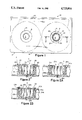
- FIG. 1 is a bottom view of a video cassette showing the invention in place in one of the spools therein.
- FIG. 2 is an enlarged cross sectional view taken along line 2--2 in FIG. 1 showing the internal structure.
- FIG. 2A is an enlarged cross sectional view similar to FIG. 2 showing a first modification.
- FIG. 2B is an enlarged cross sectional view similar to FIG. 2 showing a second modification.
- FIG. 1 illustrates a limited slip clutch 11 for preventing videotape 14 from breaking in a video cassette 10.
- the video cassette 10 includes a casing 12, a rear panel 16 with apertures 18 and two spools 19 and 20.
- the spool 20 has a central aperture 25 recessed inwardly therein.
- a friction exerting sleeve member 24 is disposed within the central aperture 25 of the spool 20.
- a moveable spline hub 22 is disposed within the sleeve member 24 so that the sleeve member is positioned between the spline hub 22 and the central aperture 25 of the spool 20.
- a bearing spindle 28 extends from the spline hub 22 and through the spool 20.
- a structure 27 is provided for holding the sleeve member 24 and the spline hub 22 within the central aperture 25 of the spool 20 but still allows rotation thereabout so that the spline hub 22 can continue to turn against the sleeve member 24 which acts as the limited slip clutch 11, when the spool 20 stops short at end of the videotape 14 thus preventing damage to the videotape.
- the holding structure 27 includes a vertical annular flange 21 formed around the central aperture 25 of the spool 20.
- a horizontal annular flange 23 is formed around exterior of the spline hub 22 with the horizontal annular flange 23 extending over the sleeve member 24.
- a retaining ring 26 is affixed to spool 20 by glue or equivalent in order to retain hub 22 in the vertical annular flange 21 of the spool 20 so that hub 22 may rotate as required.
- FIG. 2A A first modified holding structure 27a is shown in FIG. 2A in which a horizontal retaining flange 21a is formed around the central aperture 25a of the spool 20a to extend over the sleeve member 24a and the spline hub 22a.
- a second modified holding structure 27b is shown in FIG. 2B that includes a vertical annular flange 21b formed around the central aperture 25b of the spool 20b.
- the vertical annular flange 21b has an internal annular groove 34 therein.
- a horizontal annular flange 23b is formed around exterior of the spline hub 22b with the horizontal annular flange 23b extending over the sleeve member 24b.
- a split ring 32 mates within the internal annular groove 34 in the vertical annular flange 21b.
- the internal annular groove 34 in the vertical annular flange 21b of the spool 20b is formed at a forty five degree angle and the outer edge of the split ring 32 is formed at a forty five degree angle so that when the split ring 32 mates with the internal annular groove 34 in the vertical annular flange 21b it will become self locking therein.
- the material of the sleeve members 24, 24a and 24b can be fabricated out of rubber as shown in the drawings or out of plastic to best act as the limited clutch 11 or any other type of material or configuration that will exert the required pre-determined amount of friction.
- friction exerting sleeve member 24 may be fabricated from any type of material so long as it provides a pre-determined amount of friction between surfaces 25, 25a and 25b and spline hub 22, 22a and 22b respectfully so as to soften the impact on the tape of a video cassette when said video cassette is stopped by the video tape player said stopping in the prior art causing tapes to break due to the impact of sudden stopping.
- friction exerting sleeve member 24 exerts sufficient friction to rotate spool 20 when a force is exerted on spline hub 22.
Landscapes
- Mechanical Operated Clutches (AREA)
Abstract
A limited slip clutch for preventing videotape breakage in a video cassette is provided and consists of a friction exerting member positioned between a moveable spline hub and a spool in the video cassette which will allow the hub to continue to turn when the spool stops short at the end of the videotape.
Description
1. Field of the Invention
The instant invention relates generally to video cassette recorders and more specifically it relates to a limited slip clutch for preventing videotape breakage in a video cassette.
2. Description of the Prior Art
There are many parts in video cassette recorders that can wear or go bad and cause the mechanism within the machine to rewind too hard and not stop in time at the end of a videotape within a video cassette, causing the videotape to break.
The limited slip clutch will permit the videotape to reach its end without extensive pressure that can cause breakage do to faulty parts in the video cassette recorder.
A primary object of the present invention is to provide a limited slip clutch that will overcome the shortcomings of the prior art.
Another object is to provide a limited slip clutch comprising a friction exerting sleeve member positioned between a moveable spline hub and a spool in a video cassette which will allow the hub to continue to turn when the spool stops short at the end of the videotape thus preventing damage to the videotape.
An additional object is to provide a limited slip clutch in which the spool is structured to hold the sleeve member and the hub within its center and still allow them both to turn thereabout.
A most important object is to provide a slip clutch to cushion the effect that a video cassette player exerts on the video tape when said player physically stops the cassette as prior to this invention the aforsaid stopping is sudden and thus exerts a sudden impact on the tape which in turn often wears and breaks said tape.
A further object is to provide a limited slip clutch that is simple and easy to use.
A still further object is to provide a limited slip clutch that is economical in cost to manufacture.
Further objects of the invention will appear as the description proceeds.
To the accomplishment of the above and related objects, this invention may be embodied in the form illustrated in the accompanying drawings, attention being called to the fact, however, that the drawings are illustrative only, and that changes may be made in the specific construction illustrated and described within the scope of the appended claims.
FIG. 1 is a bottom view of a video cassette showing the invention in place in one of the spools therein.
FIG. 2 is an enlarged cross sectional view taken along line 2--2 in FIG. 1 showing the internal structure.
FIG. 2A is an enlarged cross sectional view similar to FIG. 2 showing a first modification.
FIG. 2B is an enlarged cross sectional view similar to FIG. 2 showing a second modification.
Turning now descriptively to the drawings, in which similar reference characters denote similar elements throughout the several views, FIG. 1 illustrates a limited slip clutch 11 for preventing videotape 14 from breaking in a video cassette 10. The video cassette 10 includes a casing 12, a rear panel 16 with apertures 18 and two spools 19 and 20.
As best seen in FIG. 2, the spool 20 has a central aperture 25 recessed inwardly therein. A friction exerting sleeve member 24 is disposed within the central aperture 25 of the spool 20. A moveable spline hub 22 is disposed within the sleeve member 24 so that the sleeve member is positioned between the spline hub 22 and the central aperture 25 of the spool 20. A bearing spindle 28 extends from the spline hub 22 and through the spool 20.
A structure 27 is provided for holding the sleeve member 24 and the spline hub 22 within the central aperture 25 of the spool 20 but still allows rotation thereabout so that the spline hub 22 can continue to turn against the sleeve member 24 which acts as the limited slip clutch 11, when the spool 20 stops short at end of the videotape 14 thus preventing damage to the videotape.
The holding structure 27 includes a vertical annular flange 21 formed around the central aperture 25 of the spool 20. A horizontal annular flange 23 is formed around exterior of the spline hub 22 with the horizontal annular flange 23 extending over the sleeve member 24. A retaining ring 26 is affixed to spool 20 by glue or equivalent in order to retain hub 22 in the vertical annular flange 21 of the spool 20 so that hub 22 may rotate as required.
A first modified holding structure 27a is shown in FIG. 2A in which a horizontal retaining flange 21a is formed around the central aperture 25a of the spool 20a to extend over the sleeve member 24a and the spline hub 22a.
A second modified holding structure 27b is shown in FIG. 2B that includes a vertical annular flange 21b formed around the central aperture 25b of the spool 20b. The vertical annular flange 21b has an internal annular groove 34 therein. A horizontal annular flange 23b is formed around exterior of the spline hub 22b with the horizontal annular flange 23b extending over the sleeve member 24b. A split ring 32 mates within the internal annular groove 34 in the vertical annular flange 21b. The internal annular groove 34 in the vertical annular flange 21b of the spool 20b is formed at a forty five degree angle and the outer edge of the split ring 32 is formed at a forty five degree angle so that when the split ring 32 mates with the internal annular groove 34 in the vertical annular flange 21b it will become self locking therein.
The material of the sleeve members 24, 24a and 24b can be fabricated out of rubber as shown in the drawings or out of plastic to best act as the limited clutch 11 or any other type of material or configuration that will exert the required pre-determined amount of friction.
It will be understood that each of the elements described above, or two or more together, may also find a useful application in other types of methods differing from the type described above.
While certain novel features of this invention have been shown and described and are pointed out in the annexed claims, it is not intended to be limited to the details above, since it will be understood that various omissions, modifications, substitutions and changes in the forms and details of the device illustrated and in its operation can be made by those skilled in the art without departing in any way from the spirit of the present invention.
Without further analysis, the foregoing will so fully reveal the gist of the present invention that others can, by applying current knowledge, readily adapt it for various applications without omitting features that, from the standpoint of prior art, fairly constitute essential characteristics of the generic or specific aspects of this invention.
Most important,friction exerting sleeve member 24 may be fabricated from any type of material so long as it provides a pre-determined amount of friction between surfaces 25, 25a and 25b and spline hub 22, 22a and 22b respectfully so as to soften the impact on the tape of a video cassette when said video cassette is stopped by the video tape player said stopping in the prior art causing tapes to break due to the impact of sudden stopping.
In normal use friction exerting sleeve member 24 exerts sufficient friction to rotate spool 20 when a force is exerted on spline hub 22.
Claims (5)
1. An apparatus for preventing videotape breakage in a video cassette which comprises:
(a) a spool having a central aperture recessed inwardly therein;
(b) a friction exerting sleeve member disposed within said central aperture of said spool;
(c) a moveable spline hub disposed within said sleeve member so that said sleeve member is positioned between said spline hub and said central aperture of said spool; and
(d) means for holding said sleeve member and said spline hub within said central aperture of said spool but still allowing rotation thereabout so that said spline hub can continue to turn against said sleeve member when said spool stops short at end of the videotape thus preventing damage to the videotape, said holding means including a vertical annular flange formed around said central aperture of said spool and a horizontal annular flange formed around the exterior of said spline hub so that said horizontal annular flange extends over said sleeve member and a retaining ring affixed to said vertical annular flange of said spool so said horizontal annular flange rides within said vertical annular flange of the spool.
2. An apparatus as recited in claim 1, wherein:
said vertical annular flange has an internal annular groove therein; and
said retaining ring is a split ring which mates within said internal annular groove in said vertical annular flange.
3. An apparatus as recited in claim 2, wherein said internal annular groove in said vertical annular flange of said spool is formed at a forty five degree angle and an outer edge of said split ring is formed at a forty five degree angle so that when said split ring mates within said internal annular groove in said vertical annular flange it will become self locking therein.
4. An apparatus as recited in claim 1, wherein said friction exerting sleeve member is fabricated out of rubber.
5. An apparatus as recited in claim 1, wherein said friction exerting sleeve member is fabricated out of plastic.
Priority Applications (1)
| Application Number | Priority Date | Filing Date | Title |
|---|---|---|---|
| US07/032,240 US4725016A (en) | 1987-03-31 | 1987-03-31 | Limited slip clutch for preventing videotape breakage in a video cassette |
Applications Claiming Priority (1)
| Application Number | Priority Date | Filing Date | Title |
|---|---|---|---|
| US07/032,240 US4725016A (en) | 1987-03-31 | 1987-03-31 | Limited slip clutch for preventing videotape breakage in a video cassette |
Publications (1)
| Publication Number | Publication Date |
|---|---|
| US4725016A true US4725016A (en) | 1988-02-16 |
Family
ID=21863860
Family Applications (1)
| Application Number | Title | Priority Date | Filing Date |
|---|---|---|---|
| US07/032,240 Expired - Fee Related US4725016A (en) | 1987-03-31 | 1987-03-31 | Limited slip clutch for preventing videotape breakage in a video cassette |
Country Status (1)
| Country | Link |
|---|---|
| US (1) | US4725016A (en) |
Cited By (3)
| Publication number | Priority date | Publication date | Assignee | Title |
|---|---|---|---|---|
| US5292086A (en) * | 1991-08-21 | 1994-03-08 | Samsung Electronics Co., Ltd. | Reel drive apparatus for magnetic tape recording and playback units |
| US5354013A (en) * | 1993-06-11 | 1994-10-11 | Ouellette Thomas C | Tape cassette fast forward clutch |
| EP1990001A1 (en) * | 2007-05-10 | 2008-11-12 | Roche Diagnostics GmbH | Piercing system and fleam conveyor |
Citations (6)
| Publication number | Priority date | Publication date | Assignee | Title |
|---|---|---|---|---|
| US3080735A (en) * | 1961-03-16 | 1963-03-12 | Edeliff Instr | Instrument shaft release clutch |
| US3389872A (en) * | 1967-01-25 | 1968-06-25 | George F. Lyman | Reel |
| US3819130A (en) * | 1972-10-24 | 1974-06-25 | Minnesota Mining & Mfg | Four-reel magnetic tape cartridge |
| US4059245A (en) * | 1975-05-20 | 1977-11-22 | Matsushita Electric Industrial Co., Ltd. | Magnetic recording-reproducing device |
| US4512535A (en) * | 1983-03-02 | 1985-04-23 | Edward John Dickson | Tape cassette with clutch assembly |
| US4606511A (en) * | 1984-08-17 | 1986-08-19 | Fuji Photo Film Co., Ltd. | Tape reel |
-
1987
- 1987-03-31 US US07/032,240 patent/US4725016A/en not_active Expired - Fee Related
Patent Citations (6)
| Publication number | Priority date | Publication date | Assignee | Title |
|---|---|---|---|---|
| US3080735A (en) * | 1961-03-16 | 1963-03-12 | Edeliff Instr | Instrument shaft release clutch |
| US3389872A (en) * | 1967-01-25 | 1968-06-25 | George F. Lyman | Reel |
| US3819130A (en) * | 1972-10-24 | 1974-06-25 | Minnesota Mining & Mfg | Four-reel magnetic tape cartridge |
| US4059245A (en) * | 1975-05-20 | 1977-11-22 | Matsushita Electric Industrial Co., Ltd. | Magnetic recording-reproducing device |
| US4512535A (en) * | 1983-03-02 | 1985-04-23 | Edward John Dickson | Tape cassette with clutch assembly |
| US4606511A (en) * | 1984-08-17 | 1986-08-19 | Fuji Photo Film Co., Ltd. | Tape reel |
Cited By (7)
| Publication number | Priority date | Publication date | Assignee | Title |
|---|---|---|---|---|
| US5292086A (en) * | 1991-08-21 | 1994-03-08 | Samsung Electronics Co., Ltd. | Reel drive apparatus for magnetic tape recording and playback units |
| US5354013A (en) * | 1993-06-11 | 1994-10-11 | Ouellette Thomas C | Tape cassette fast forward clutch |
| EP1990001A1 (en) * | 2007-05-10 | 2008-11-12 | Roche Diagnostics GmbH | Piercing system and fleam conveyor |
| WO2008138443A1 (en) * | 2007-05-10 | 2008-11-20 | Roche Diagnostics Gmbh | Pricking system and lancet carrier strip |
| US20100145376A1 (en) * | 2007-05-10 | 2010-06-10 | Ahmet Konya | Puncturing system and lancet carrier tape |
| US9480420B2 (en) | 2007-05-10 | 2016-11-01 | Roche Diabetes Care, Inc. | Puncturing system and lancet carrier tape |
| US10357193B2 (en) | 2007-05-10 | 2019-07-23 | Roche Diabetes Care, Inc. | Puncturing system and lancet carrier tape |
Similar Documents
| Publication | Publication Date | Title |
|---|---|---|
| US4725016A (en) | Limited slip clutch for preventing videotape breakage in a video cassette | |
| US3140832A (en) | Sound tape magazine or the like | |
| US3739998A (en) | Reel driving device | |
| US3304019A (en) | Single reel endless tape or film cartridge | |
| US5301073A (en) | Take-up pulley with torque-limiting mechanism for magnetic recording and reproducing apparatus | |
| US4505440A (en) | Tape cassette | |
| US4391416A (en) | Reel shaft device of a magnetic recording tape running apparatus | |
| US3706422A (en) | Endless tape cartridge | |
| JPS6030843Y2 (en) | reel axis | |
| US5305171A (en) | Tape cassette speed-release clutch | |
| KR0169408B1 (en) | Recording reproducing apparatus having clutch mechanism | |
| JP2535966B2 (en) | Reel of magnetic recording / reproducing device | |
| KR950006944Y1 (en) | Tape reel arrival structure for video tape cassette | |
| US6431484B2 (en) | Friction type of power transmission mechanism for driving reel support in VTR | |
| KR960006567Y1 (en) | Tape recorder reel table | |
| KR100385974B1 (en) | Reel brake apparatus of tape recorder | |
| KR900005437Y1 (en) | Anti-vibration endless tape magazine | |
| JPS599427Y2 (en) | Tape reel support device for tape recorder | |
| JPH0348744Y2 (en) | ||
| US20030098376A1 (en) | Idler mechanism for magnetic tape device and tape device | |
| KR20040061073A (en) | Shaft assembly and Real-apparatus for tape recorder | |
| JPS6017098Y2 (en) | Endless cassette tape device | |
| JPH0413191Y2 (en) | ||
| JPH08212628A (en) | Falling preventing mechanism for reel base | |
| JPS6336549Y2 (en) |
Legal Events
| Date | Code | Title | Description |
|---|---|---|---|
| REMI | Maintenance fee reminder mailed | ||
| LAPS | Lapse for failure to pay maintenance fees | ||
| FP | Lapsed due to failure to pay maintenance fee |
Effective date: 19920216 |
|
| STCH | Information on status: patent discontinuation |
Free format text: PATENT EXPIRED DUE TO NONPAYMENT OF MAINTENANCE FEES UNDER 37 CFR 1.362 |