US4714554A - Cross-axis synchronous flow-through coil planet centrifuge free of rotary seals: apparatus and method for performing countercurrent chromatography - Google Patents
Cross-axis synchronous flow-through coil planet centrifuge free of rotary seals: apparatus and method for performing countercurrent chromatography Download PDFInfo
- Publication number
- US4714554A US4714554A US06/915,797 US91579786A US4714554A US 4714554 A US4714554 A US 4714554A US 91579786 A US91579786 A US 91579786A US 4714554 A US4714554 A US 4714554A
- Authority
- US
- United States
- Prior art keywords
- column
- holding means
- longitudinal axis
- rotation
- central shaft
- Prior art date
- Legal status (The legal status is an assumption and is not a legal conclusion. Google has not performed a legal analysis and makes no representation as to the accuracy of the status listed.)
- Expired - Lifetime
Links
- 238000004185 countercurrent chromatography Methods 0.000 title claims abstract description 21
- 238000000034 method Methods 0.000 title claims description 12
- 230000001360 synchronised effect Effects 0.000 title abstract description 16
- 230000005526 G1 to G0 transition Effects 0.000 claims description 8
- 239000006260 foam Substances 0.000 claims description 7
- 239000007788 liquid Substances 0.000 claims description 5
- 238000013375 chromatographic separation Methods 0.000 claims description 2
- 239000003480 eluent Substances 0.000 claims 4
- 239000012530 fluid Substances 0.000 claims 4
- 230000033001 locomotion Effects 0.000 abstract description 23
- 239000013598 vector Substances 0.000 abstract description 12
- ZZUFCTLCJUWOSV-UHFFFAOYSA-N furosemide Chemical compound C1=C(Cl)C(S(=O)(=O)N)=CC(C(O)=O)=C1NCC1=CC=CO1 ZZUFCTLCJUWOSV-UHFFFAOYSA-N 0.000 description 13
- 239000002904 solvent Substances 0.000 description 9
- 230000001133 acceleration Effects 0.000 description 8
- 239000000523 sample Substances 0.000 description 8
- 238000010586 diagram Methods 0.000 description 7
- 238000000926 separation method Methods 0.000 description 7
- 230000009977 dual effect Effects 0.000 description 5
- 230000014759 maintenance of location Effects 0.000 description 4
- 239000012488 sample solution Substances 0.000 description 4
- LRHPLDYGYMQRHN-UHFFFAOYSA-N N-Butanol Chemical compound CCCCO LRHPLDYGYMQRHN-UHFFFAOYSA-N 0.000 description 2
- 238000004458 analytical method Methods 0.000 description 2
- 150000001875 compounds Chemical class 0.000 description 2
- 230000008878 coupling Effects 0.000 description 2
- 238000010168 coupling process Methods 0.000 description 2
- 238000005859 coupling reaction Methods 0.000 description 2
- 230000000694 effects Effects 0.000 description 2
- 238000004804 winding Methods 0.000 description 2
- XAGFODPZIPBFFR-UHFFFAOYSA-N aluminium Chemical compound [Al] XAGFODPZIPBFFR-UHFFFAOYSA-N 0.000 description 1
- 229910052782 aluminium Inorganic materials 0.000 description 1
- 230000001174 ascending effect Effects 0.000 description 1
- 230000009286 beneficial effect Effects 0.000 description 1
- 238000005119 centrifugation Methods 0.000 description 1
- 238000004587 chromatography analysis Methods 0.000 description 1
- 238000004440 column chromatography Methods 0.000 description 1
- 238000012864 cross contamination Methods 0.000 description 1
- 238000007598 dipping method Methods 0.000 description 1
- 238000000605 extraction Methods 0.000 description 1
- 230000005484 gravity Effects 0.000 description 1
- 238000002347 injection Methods 0.000 description 1
- 239000007924 injection Substances 0.000 description 1
- 230000003993 interaction Effects 0.000 description 1
- 239000000203 mixture Substances 0.000 description 1
- 102000004196 processed proteins & peptides Human genes 0.000 description 1
- 108090000765 processed proteins & peptides Proteins 0.000 description 1
- 239000002356 single layer Substances 0.000 description 1
- 239000007787 solid Substances 0.000 description 1
- 238000000638 solvent extraction Methods 0.000 description 1
- 238000006467 substitution reaction Methods 0.000 description 1
- 239000004094 surface-active agent Substances 0.000 description 1
- 230000009466 transformation Effects 0.000 description 1
Images


Classifications
-
- G—PHYSICS
- G01—MEASURING; TESTING
- G01N—INVESTIGATING OR ANALYSING MATERIALS BY DETERMINING THEIR CHEMICAL OR PHYSICAL PROPERTIES
- G01N30/00—Investigating or analysing materials by separation into components using adsorption, absorption or similar phenomena or using ion-exchange, e.g. chromatography or field flow fractionation
- G01N30/02—Column chromatography
- G01N30/26—Conditioning of the fluid carrier; Flow patterns
- G01N30/38—Flow patterns
- G01N30/42—Flow patterns using counter-current
-
- B—PERFORMING OPERATIONS; TRANSPORTING
- B01—PHYSICAL OR CHEMICAL PROCESSES OR APPARATUS IN GENERAL
- B01D—SEPARATION
- B01D15/00—Separating processes involving the treatment of liquids with solid sorbents; Apparatus therefor
- B01D15/08—Selective adsorption, e.g. chromatography
- B01D15/10—Selective adsorption, e.g. chromatography characterised by constructional or operational features
- B01D15/18—Selective adsorption, e.g. chromatography characterised by constructional or operational features relating to flow patterns
- B01D15/1807—Selective adsorption, e.g. chromatography characterised by constructional or operational features relating to flow patterns using counter-currents, e.g. fluidised beds
-
- B—PERFORMING OPERATIONS; TRANSPORTING
- B04—CENTRIFUGAL APPARATUS OR MACHINES FOR CARRYING-OUT PHYSICAL OR CHEMICAL PROCESSES
- B04B—CENTRIFUGES
- B04B5/00—Other centrifuges
- B04B5/02—Centrifuges consisting of a plurality of separate bowls rotating round an axis situated between the bowls
Definitions
- This invention relates generally to chromatography and more specifically to countercurrent chromatography.
- Countercurrent chromatography utilizes complex hydrodynamic interaction of two immiscible solvent phases in a tubular column space free of solid support. Retention of the stationary phase and solute partitioning take place in an open column space by the aid of a suitable acceleration field particularly provided by coil planet centrifugation.
- a series of flow-through centrifuge systems has been developed for performing CCC. Among those, the most useful systems were found to be the coil planet centrifuges which produce synchronous planetary motion of the column holder.
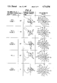
- FIG. 1 shows the orientation and motion of a cylindrical coil holder under various types of the synchronous planetary motion.
- Type I the holder revolves around the central axis of the centrifuge system while it synchronously counterrotates about its own axis at the same angular velocity.
- This synchronous counterrotation of the holder steadily unwinds the twist of the flow tubes made by revolution, thus totally eliminating the need for the conventional rotary seal device.
- This twist free flow-through mechanism works equally well in other synchronous planetary motions with tilted (Types I-L and I-X), horizontal (Types L and X), dipping (Types J-L and J-X), and inverted (Type J) orientations of the holder.
- Type I U.S. Pat. No. 3,775,309
- Type I-L U.S. Pat. No. 3,994,805
- Type L U.S. Pat. No. 3,856,669
- Type J-L U.S. Patent pending
- Type J U.S. Pat. No. 4,058,460
- Types J and J-L produced the unilateral hydrodynamic distribution of the two solvent phases in the coiled column and are ideal for performing high-speed CCC which is characterized by high peak resolution and excellent retention of the stationary phase against a high flow rate of the mobile phase.
- This unique performance of these two centrifuge systems are apparently derived from the particular pattern of the acceleration field generated by the planetary motion of the holder.
- FIG. 2 illustrates the distribution of the centrifugal force vectors in those five types of the synchronous planetary motion.
- three dimensional orientation of the force vector is expressed in two force components, one acting in the X b -Y b plane (shown by arrows) and the other acting along the Z b -axis (shown by vertical columns) according to the reference X b -Y b -Z b coordinate system indicated for each planetary motion.
- the force distribution diagrams for Type J-L and Type J show asymmetrical distribution of strong radial force components, which is considered to be the cause for the unilateral hydrodynamic distribution of the two solvent phases in the rotating column.
- the second force component acting along the Z b -axis (columns) in Type J-L is also considered beneficial for introducing efficient mixing of the two solvent phases or improving the retention of the stationary phase depending on the configuration of the coiled column on the rotating holder.
- the present invention is based on a new type of the synchronous planetary motion, Type X,illustrated in FIG. 1.
- Type X a new type of the synchronous planetary motion
- the two axes of the centrifuge system i.e., the axis of the centrifuge (axis of revolution) and the axis of the holder (axis of rotation) cross each other at a 90° angle if viewed sideways.
- FIG. 1 shows various planetary motion schemes.
- FIG. 2 shows the angle, planetary motion, reference coordinate frame and force distribution for the planetary motion schemes shown in FIG. 1.
- FIG. 3A schematically illustrates synchronous planetary motion of a point P on a centrifuge.
- FIG. 3B schematically illustrates the synchronous planetary motion of the point P on a centrifuge according to the present invention, in the x-y-z coordinate system.
- FIG. 3C schematically illustrates the motion illustrated in FIG. 3B, in the X b -Y b -Z b coordinate system.
- FIG. 3D schematically illustrates force vectors arising in the method and apparatus of the present invention.
- FIG. 4A is a side elevation of a preferred apparatus according to the present invention.
- FIG. 4B is a cross-section of the apparatus of FIG. 4A, taken along line B--B.
- FIGS. 5A-5D illustrate various coil windings useful in the present invention.
- FIG. 5E schematically illustrates a column design for foam countercurrent column chromatography.
- FIGS. 6A-6C schematically illustrate preferred separation schemes for use with the present invention.
- FIG. 7 shows a cross-sectional view of another preferred embodiment of an apparatus according to the present invention, the view being analogous to that of FIG. 4B.
- FIG. 3B shows an x-y-z coordinate system where z-axis coincides with the central axis and the center of the discoid body (Q) circles around point O in the x-y plane.
- the arbitrary point on the discoid body and the center of the discoid body are initially located on the x-axis at P o and Q o , respectively.
- the discoid body undergoes a synchronous planetary motion as described above: The body revolves around the z-axis and rotates about its own axis at the same angular velocity, ⁇ . After a lapse of time t, the arbitrary point moves to point P and the center of the discoid body to point Q. Then the location of point P (x, y, z) is expressed in the following equations:
- ⁇ Xb , ⁇ Yb , and ⁇ Zb indicate the acceleration vectors acting along the corresponding coordinate axes.
- the centrifugal force vectors (same magnitude with the acceleration acting in the opposite direction) at various points on the discoid body are computed and diagrammatically illustrated in FIG. 3D.
- two force vectors, - ⁇ Xb and - ⁇ Yb are combined into a single vector forming various angles from the x-axis, whereas the third force vector, - ⁇ Zb , which acts perpendicularly to the X b -Y b plane, is drawn in the vertical direction along the Y b -axis.
- the ascending column indicates the force acting upward (Z>0) and the descending column, the force acting downward (Z ⁇ 0).
- Several concentric circles around point 0 b (the center of the discoid body) indicate the location on the discoid body corresponding to various ⁇ values labelled in the diagram.
- the force distribution diagram (FIG. 3D) for the present system resembles those obtained from the Types J and J-L synchronous planetary motions (FIG. 2). This finding strongly suggests that the present system is capable of performing highspeed CCC with a multilayer coil. In comparison with the Type J-L planetary motion, the present system, produces symmetrical distribution of the second components (columns) promising that the system would provide more thorough mixing of the two solvent phases in the column. This efficient mixing is extremely important for the application of different types of the separation column such as eccentric coil assembly and toroidal coil.
- the force distribution pattern of the present system also suggests that large preparative-scale separations can be efficiently performed by applying slow rotation of a large diameter coil.
- gravity acts to retain the stationary phase in the column while the second force component acting along the Z b -axis introduces efficient mixing of the two solvent phases across the diameter of the tube to reduce mass transfer resistance with minimum sample band broadening.
- the system may also be applied to dual CCC where two solvent phases literally undergo countercurrent flow through the coiled column while the sample is continuously fed through the sample feed line connected at the middle portion of the column. Although this operation requires five flow tubes, the present system permits the use of multiple flow tubes without risk of leakage or cross contamination caused by the use of conventional rotary seals.
- FIG. 4A illustrates a cross-sectional view across the central axis of the centrifuge 10.
- the motor 12 (left) drives the rotary frame 14 around the vertical axis of the centrifuge by a pair of toothed pulleys 16, 18 coupled with a toothed belt 20.
- the rotary frame 14 consists of upper and lower aluminum plates 22 and 24, respectively, rigidly bridged together with a pair of side plates 26, 28, and holds a countershaft 30 (right) and a column holder 32 on one side and a counterweight holder 34 on the opposite side for balancing the centrifuge system 10 (see FIG. 4B).
- the countershaft 30 is equipped with a toothed pulley 36 at the bottom and a miter gear 38 in its middle portion.
- the stationary pulley 40 mounted on the central axis of the centrifuge 109 is coupled with a toothed belt 42 to the identical toothed pulley 36 mounted at the bottom of the countershaft 30.
- This pulley coupling causes synchronous counterrotation of the countershaft 30 on the revolving rotary frame 14.
- This motion of the countershaft 30 is further conveyed to the column holder 32 by coupling a pair of identical miter gears 38, 44, one mounted on the countershaft and the other on the column holder shaft. Consequently, the column holder 32 rotates about its own axis at an angular velocity equal to that of revolution as previously described in FIG. 3A.
- FIG. 4B shows a cross-sectional view through the central axis of the column holder.
- the column holder and the counterweight holder are symmetrically positioned to balance the centrifuge system.
- Both holders 32, 34 can be removed from the rotary frame by loosening a pair of screws 46a, 46b.
- a pair of flow tubes 48a, 48b from the holder 32 is first passed through the hole 50 on the holder shaft 52 and then through the side hole 54 made on the central shaft 56 where it is supported by a stationary tube support 58 projecting down from the center of the centrifuge 10 top. As described earlier, these flow tubes are free from twisting.
- FIGS. 5A-5E schematically illustrates various types of coiled columns used with the present apparatus.
- FIG. 5A is a single layer coil 60 coaxially mounted around the holder 32. This type of the column is useful for continuous extraction of the biological compounds present in a large volume of the sample solution.
- FIG. 5B shows a multilayer coil 60' coaxially mounted around the spool-shaped holder 32 (also shown in FIG. 4B). This column configuration is capable of yielding highly efficient chromatographic separations in a short period of time and therefore used for performing high-speed CCC.
- FIG. 5C shows an eccentric coil assembly 60" which is made by connecting multiple units of coils in series and arranging it around the holder 32.
- FIGS. 5D is called a toroidal coil and prepared by winding a fine coiled column 60"' around the holder 32. This column is most useful for analytical-scale separations.
- FIG. 5E schematically shows the layout 100 of the coiled column 101 for dual CCC including liquid-liquid dual CCC and foam CCC. As shown in the diagram, the column is equipped with five flow lines (102, 104, 106, 108, 110), i.e., inlet (102, 104) and outlet (106, 108) lines opening at each end and a sample feed line (110) at the middle portion of the column 101.
- FIGS. 6A-6C diagrammatically illustrate three modes of operation for the cross-axis synchronous flow-through coil planet centrifuge.
- the standard setup 200 for performing high-speed CCC is shown in FIG. 6A.
- the column 202 is first entirely filled with the stationary phase and the sample solution 204 is injected through the sample port 206. Then the column 202 is spun at the desired revolutional speed (usually at 800 rpm) while the mobile phase is eluted through the column in the proper mode, i.e., the head phase from the tail toward the head or the tail phase from the head toward the tail.
- the effluent from the outlet of the column is continuously monitored with a uv monitor 208 (the monitored reading being recorded on recorder 210) and then fractionated with a fraction collector 212.
- FIGS. 6B and 6C show dual CCC operation using a coiled column with five flow lines.
- the column 302 is first entirely filled with either phase 304, 306 or the mixture of both phases, while the sample feed line 308 is closed. Then the head phase 306 and the tail phase 304 are simultaneously fed from the tail (pump II) 310 and the head (pump I) 312 of the column 302, respectively, while the column 302 is rotated at the desired speed.
- the opening of the needle valve 314 on the head side is adjusted in such a way that the eluting rate through the valve 314 is equal to the feeding rate from the tail end (pump II) 310.
- sample solution is introduced through the sample feed line 308 either batchwise or in a continuous fashion (pump III) 316.
- Eluate through each end of the column 318, 320 is monitored and fractionated with a fraction collector 322, 324.
- FIG. 6C illustrates procedure for foam CCC.
- the separation is initiated by rotating the column 402 at the desired speed (usually at 500 rpm). Then, the liquid containing surfactant 304 is introduced through the tail end of the column 302 (pump I) 306 while the N 2 gas phase 308 is fed through the head end at 80 psi. The needle valve 310 on the flow line 312 from the head end is opened so that the desired, amount of foam 314 is eluted through the tail outlet. After the steady state hydrodynamic equilibrium is reached, the sample solution is introduced through the sample feed line 316 either by a batch injection or in a continuous fashion (pump II) 318. The enriched foam 314 is collected through the tail with a foam collector 310 while the stripped liquid 312 is collected through the head with a fraction collector 322.
- FIG. 7 shows another embodiment 10' of the present invention, in the same view as the first embodiment is shown in FIG. 4B.
- a stationary miter gear 500 is rigidly mounted to the bottom plate of the centrifuge concentrically around central shaft 56.
- the rotation of central shaft 56, along with rotary plate 24, causes the rotation of shafts 502, 504 by the engagement of stationary miter gear 500 with identical planetary miter gears 506 and 508, respectively.
- Shafts 502, 504 are attached at their outer ends to toothed pulleys 510 and 512, respectively. Pulleys 510, 512 turn, respectively, toothed belts 514 and 516.
- Parts 26', 28', 50', 52', 46a' and 46b' are analogous to parts 26, 28, 50, 52, 46a and 46b respectively.
- FIG. 7 The design of the apparatus shown in FIG. 7 is superior to that in FIGS. 4A and B in terms of mechanical stability and dynamic balancing and therefore suitable to application of high revoluational speed.
Landscapes
- Chemical & Material Sciences (AREA)
- Analytical Chemistry (AREA)
- General Health & Medical Sciences (AREA)
- Life Sciences & Earth Sciences (AREA)
- Health & Medical Sciences (AREA)
- Biochemistry (AREA)
- Physics & Mathematics (AREA)
- General Physics & Mathematics (AREA)
- Immunology (AREA)
- Pathology (AREA)
- Chemical Kinetics & Catalysis (AREA)
- Centrifugal Separators (AREA)
- Treatment Of Liquids With Adsorbents In General (AREA)
Abstract
Description
x=R cos θ-r cos.sup.2 θ (1)
y=R sin θ-r sin θcos θ (2)
z=r sin θ (3)
d.sup.2 x/dt.sup.2 =-Rω.sup.2 cos θ+2rω.sup.2 cis 2θ=-Rω.sup.2 (cos θ-2β cos 2θ) (4)
d.sup.2 y/dt.sup.2 =-Rω.sup.2 sin θ+2rω.sup.2 sin 2θ=-Rω.sup.2 (sin θ-2β sin 2θ)(5)
d.sup.2 z/dt.sup.2 =-rω.sup.2 sin θ=-Rω.sup.2 β sin θ (6)
α.sub.Xb =(d.sup.2 x/dt.sup.2) cos θ+(d.sup.2 y/dt.sup.2) sin θ=-Rω.sup.2 (1-.sup.2 β cos θ) (7)
α.sub.Yb =d.sup.2 z/dt.sup.2 =-Rω.sup.2 β sin θ(8)
α.sub.Zb =(d.sup.2 x/dt.sup.2) sin θ-(d.sup.2 y/dt.sup.2) cos θ=-Rω.sup.2 2β sin θ (9)
Claims (17)
Priority Applications (2)
| Application Number | Priority Date | Filing Date | Title |
|---|---|---|---|
| US06/915,797 US4714554A (en) | 1986-10-03 | 1986-10-03 | Cross-axis synchronous flow-through coil planet centrifuge free of rotary seals: apparatus and method for performing countercurrent chromatography |
| JP62249652A JPS6391560A (en) | 1986-10-03 | 1987-10-02 | Transverse axis type synchronous system conduction coil-planet centrifugal separator requiring no rotary seal and counterflow chromatographic separation method |
Applications Claiming Priority (1)
| Application Number | Priority Date | Filing Date | Title |
|---|---|---|---|
| US06/915,797 US4714554A (en) | 1986-10-03 | 1986-10-03 | Cross-axis synchronous flow-through coil planet centrifuge free of rotary seals: apparatus and method for performing countercurrent chromatography |
Publications (1)
| Publication Number | Publication Date |
|---|---|
| US4714554A true US4714554A (en) | 1987-12-22 |
Family
ID=25436261
Family Applications (1)
| Application Number | Title | Priority Date | Filing Date |
|---|---|---|---|
| US06/915,797 Expired - Lifetime US4714554A (en) | 1986-10-03 | 1986-10-03 | Cross-axis synchronous flow-through coil planet centrifuge free of rotary seals: apparatus and method for performing countercurrent chromatography |
Country Status (2)
| Country | Link |
|---|---|
| US (1) | US4714554A (en) |
| JP (1) | JPS6391560A (en) |
Cited By (11)
| Publication number | Priority date | Publication date | Assignee | Title |
|---|---|---|---|---|
| US5104531A (en) * | 1990-02-26 | 1992-04-14 | The United States Of America As Represented By The Department Of Health And Human Services | Cross-axis synchronous flow through coil planet centrifuge for large scale preparative countercurrent chromatography |
| US5114589A (en) * | 1991-01-17 | 1992-05-19 | The United States Government As Represented By The Secretary Of The Department Of Health And Human Services | Type-XLL cross-axis synchronous flow-through coil planet centrifuge for separation of biopolymers |
| US5217608A (en) * | 1988-07-21 | 1993-06-08 | The Research Foundation Of State University Of New York | Multi-column planet centrifuge chromatograph |
| US5354473A (en) * | 1992-09-18 | 1994-10-11 | The United States Of America As Represented By The Departent Of Health And Human Services | Method for concentrating a solute by countercurrent chromatography |
| US5520817A (en) * | 1994-10-04 | 1996-05-28 | Biologica Co. | Method of fractionating components in liquid chromatography |
| CN1295023C (en) * | 2004-10-26 | 2007-01-17 | 昆明理工大学 | Alternating force-field type centrifugal ore-dressing machine |
| WO2010010366A1 (en) * | 2008-07-24 | 2010-01-28 | Brunel University | Counter-current chromatographic arrangement |
| US20100120597A1 (en) * | 2007-02-02 | 2010-05-13 | Hawes David W | Centrifuge with non-synchronous drive system |
| CN106706801A (en) * | 2017-02-15 | 2017-05-24 | 山东省分析测试中心 | Liquid-liquid distributing chromatographic instrument with rotating gear ring |
| RU2643539C1 (en) * | 2016-12-02 | 2018-02-02 | Федеральное государственное автономное образовательное учреждение высшего образования "Национальный исследовательский технологический университет "МИСиС" | Method of fractioning polydisperse mixtures of nano- and micro particles |
| CN116183756A (en) * | 2023-02-03 | 2023-05-30 | 宜宾四川大学产业技术研究院 | Unwind frame disconnect-type high-speed countercurrent chromatography |
Families Citing this family (2)
| Publication number | Priority date | Publication date | Assignee | Title |
|---|---|---|---|---|
| JPH02243957A (en) * | 1988-08-22 | 1990-09-28 | Us Government | Rotation-free seal type passage oil planet centrifugal tube apparatus |
| JP5737671B2 (en) * | 2010-11-16 | 2015-06-17 | 国立大学法人九州工業大学 | Waste water treatment equipment containing metal ions |
Citations (17)
| Publication number | Priority date | Publication date | Assignee | Title |
|---|---|---|---|---|
| US3775309A (en) * | 1972-07-27 | 1973-11-27 | Department Of Health Education | Countercurrent chromatography with flow-through coil planet centrifuge |
| US3856669A (en) * | 1973-07-02 | 1974-12-24 | Department Of Health Education | Elution centrifuge-apparatus and method |
| US3994805A (en) * | 1975-07-22 | 1976-11-30 | The United States Of America As Represented By The Secretary Of The Department Of Health, Education And Welfare | Angle rotor countercurrent chromatography |
| US4051025A (en) * | 1976-09-29 | 1977-09-27 | The United States Of America As Represented By The Department Of Health, Education And Welfare | Preparative countercurrent chromatography with a slowly rotating helical tube array |
| US4058460A (en) * | 1977-03-17 | 1977-11-15 | The United States Of America As Represented By The Department Of Health, Education And Welfare | Horizontal flow-through coil planet centrifuge without rotating seals |
| US4151089A (en) * | 1978-05-17 | 1979-04-24 | The United States Of America As Represented By The Secretary Of The Department Of Health, Education And Welfare | Device for high efficiency continuous countercurrent extraction using a rotating helical tube |
| US4162761A (en) * | 1977-11-30 | 1979-07-31 | The United States Of America As Represented By The Department Of Health, Education And Welfare | Flow-through coil planet centrifuges with adjustable rotation/revolution of column |
| US4182678A (en) * | 1978-12-14 | 1980-01-08 | The United States Of America As Represented By The Secretary Of The Department Of Health, Education & Welfare | Micro-scale countercurrent chromatograph |
| US4228009A (en) * | 1979-06-04 | 1980-10-14 | The United States Of America As Represented By The Department Of Health, Education And Welfare | Toroidal coil planet centrifuge |
| US4228950A (en) * | 1978-12-04 | 1980-10-21 | The United States Of America As Represented By The Department Of Health, Education And Welfare | Horizontal flow-through coil planet centrifuge |
| US4321138A (en) * | 1981-02-02 | 1982-03-23 | The United States Of America As Represented By The Department Of Health And Human Services | Method and apparatus for preparative countercurrent chromatography employing a rotating column assembly |
| US4324661A (en) * | 1980-05-09 | 1982-04-13 | The United States Of America As Represented By The Department Of Health, Education And Welfare | Apparatus and method for continuous countercurrent extraction and particle separation |
| US4414108A (en) * | 1980-05-09 | 1983-11-08 | The United States Of America As Represented By The Department Of Health And Human Services | Apparatus and method for continuous countercurrent extraction and particle separation |
| US4430216A (en) * | 1982-09-09 | 1984-02-07 | The United States Of America As Represented By The Department Of Health And Human Services | High speed preparative countercurrent chromatography with a multiple layer coiled column |
| US4487693A (en) * | 1982-09-09 | 1984-12-11 | The United States Of America As Represented By The Department Of Health And Human Services | Multi-layer coil countercurrent chromatograph with adjustable revolutional radius |
| US4532039A (en) * | 1983-03-14 | 1985-07-30 | The United States Of America As Represented By The Secretary Of The Department Of Health And Human Services | Multi-layer coil assembly coaxially mounted around the rotary axis for preparatory countercurrent chromatography |
| US4615805A (en) * | 1985-09-13 | 1986-10-07 | The United States Of America As Represented By The Department Of Health And Human Services | Method for continuous countercurrent foam separation |
-
1986
- 1986-10-03 US US06/915,797 patent/US4714554A/en not_active Expired - Lifetime
-
1987
- 1987-10-02 JP JP62249652A patent/JPS6391560A/en active Pending
Patent Citations (17)
| Publication number | Priority date | Publication date | Assignee | Title |
|---|---|---|---|---|
| US3775309A (en) * | 1972-07-27 | 1973-11-27 | Department Of Health Education | Countercurrent chromatography with flow-through coil planet centrifuge |
| US3856669A (en) * | 1973-07-02 | 1974-12-24 | Department Of Health Education | Elution centrifuge-apparatus and method |
| US3994805A (en) * | 1975-07-22 | 1976-11-30 | The United States Of America As Represented By The Secretary Of The Department Of Health, Education And Welfare | Angle rotor countercurrent chromatography |
| US4051025A (en) * | 1976-09-29 | 1977-09-27 | The United States Of America As Represented By The Department Of Health, Education And Welfare | Preparative countercurrent chromatography with a slowly rotating helical tube array |
| US4058460A (en) * | 1977-03-17 | 1977-11-15 | The United States Of America As Represented By The Department Of Health, Education And Welfare | Horizontal flow-through coil planet centrifuge without rotating seals |
| US4162761A (en) * | 1977-11-30 | 1979-07-31 | The United States Of America As Represented By The Department Of Health, Education And Welfare | Flow-through coil planet centrifuges with adjustable rotation/revolution of column |
| US4151089A (en) * | 1978-05-17 | 1979-04-24 | The United States Of America As Represented By The Secretary Of The Department Of Health, Education And Welfare | Device for high efficiency continuous countercurrent extraction using a rotating helical tube |
| US4228950A (en) * | 1978-12-04 | 1980-10-21 | The United States Of America As Represented By The Department Of Health, Education And Welfare | Horizontal flow-through coil planet centrifuge |
| US4182678A (en) * | 1978-12-14 | 1980-01-08 | The United States Of America As Represented By The Secretary Of The Department Of Health, Education & Welfare | Micro-scale countercurrent chromatograph |
| US4228009A (en) * | 1979-06-04 | 1980-10-14 | The United States Of America As Represented By The Department Of Health, Education And Welfare | Toroidal coil planet centrifuge |
| US4324661A (en) * | 1980-05-09 | 1982-04-13 | The United States Of America As Represented By The Department Of Health, Education And Welfare | Apparatus and method for continuous countercurrent extraction and particle separation |
| US4414108A (en) * | 1980-05-09 | 1983-11-08 | The United States Of America As Represented By The Department Of Health And Human Services | Apparatus and method for continuous countercurrent extraction and particle separation |
| US4321138A (en) * | 1981-02-02 | 1982-03-23 | The United States Of America As Represented By The Department Of Health And Human Services | Method and apparatus for preparative countercurrent chromatography employing a rotating column assembly |
| US4430216A (en) * | 1982-09-09 | 1984-02-07 | The United States Of America As Represented By The Department Of Health And Human Services | High speed preparative countercurrent chromatography with a multiple layer coiled column |
| US4487693A (en) * | 1982-09-09 | 1984-12-11 | The United States Of America As Represented By The Department Of Health And Human Services | Multi-layer coil countercurrent chromatograph with adjustable revolutional radius |
| US4532039A (en) * | 1983-03-14 | 1985-07-30 | The United States Of America As Represented By The Secretary Of The Department Of Health And Human Services | Multi-layer coil assembly coaxially mounted around the rotary axis for preparatory countercurrent chromatography |
| US4615805A (en) * | 1985-09-13 | 1986-10-07 | The United States Of America As Represented By The Department Of Health And Human Services | Method for continuous countercurrent foam separation |
Non-Patent Citations (6)
| Title |
|---|
| Ito, "Application of the Elution Centrifuge to Separation of Polynucleotides with the Use of Polymer Phase Systems Science, vol. 182, pp. 391-393 (1973). |
| Ito, Application of the Elution Centrifuge to Separation of Polynucleotides with the Use of Polymer Phase Systems Science, vol. 182, pp. 391 393 (1973). * |
| Ito, New Continuous Extraction Method with a Coil Planet Centrifuge Journal of Chromatography, 207 (1981) 161 169. * |
| Ito, New Continuous Extraction Method with a Coil Planet Centrifuge Journal of Chromatography, 207 (1981) 161-169. |
| Perry s Chemical Engineer s Handbook, Fourth Edition McGraw Hill, 1969, pp. 24 87 and 24 88. * |
| Perry's Chemical Engineer's Handbook, Fourth Edition McGraw Hill, 1969, pp. 24-87 and 24-88. |
Cited By (15)
| Publication number | Priority date | Publication date | Assignee | Title |
|---|---|---|---|---|
| US5217608A (en) * | 1988-07-21 | 1993-06-08 | The Research Foundation Of State University Of New York | Multi-column planet centrifuge chromatograph |
| US5104531A (en) * | 1990-02-26 | 1992-04-14 | The United States Of America As Represented By The Department Of Health And Human Services | Cross-axis synchronous flow through coil planet centrifuge for large scale preparative countercurrent chromatography |
| US5114589A (en) * | 1991-01-17 | 1992-05-19 | The United States Government As Represented By The Secretary Of The Department Of Health And Human Services | Type-XLL cross-axis synchronous flow-through coil planet centrifuge for separation of biopolymers |
| WO1992012780A1 (en) * | 1991-01-17 | 1992-08-06 | The United States Of America, Represented By The Secretary, United States Department Of Commerce | Type-xll cross-axis synchronous flow-through coil planet centrifuge for separation of biopolymers |
| US5354473A (en) * | 1992-09-18 | 1994-10-11 | The United States Of America As Represented By The Departent Of Health And Human Services | Method for concentrating a solute by countercurrent chromatography |
| US5674388A (en) * | 1993-12-20 | 1997-10-07 | Biologica Co. | Apparatus for fractionating components in liquid chromatography |
| US5520817A (en) * | 1994-10-04 | 1996-05-28 | Biologica Co. | Method of fractionating components in liquid chromatography |
| CN1295023C (en) * | 2004-10-26 | 2007-01-17 | 昆明理工大学 | Alternating force-field type centrifugal ore-dressing machine |
| US20100120597A1 (en) * | 2007-02-02 | 2010-05-13 | Hawes David W | Centrifuge with non-synchronous drive system |
| WO2010010366A1 (en) * | 2008-07-24 | 2010-01-28 | Brunel University | Counter-current chromatographic arrangement |
| RU2643539C1 (en) * | 2016-12-02 | 2018-02-02 | Федеральное государственное автономное образовательное учреждение высшего образования "Национальный исследовательский технологический университет "МИСиС" | Method of fractioning polydisperse mixtures of nano- and micro particles |
| CN106706801A (en) * | 2017-02-15 | 2017-05-24 | 山东省分析测试中心 | Liquid-liquid distributing chromatographic instrument with rotating gear ring |
| CN106706801B (en) * | 2017-02-15 | 2023-10-20 | 山东省分析测试中心 | Liquid-liquid distribution chromatograph with rotary toothed ring |
| CN116183756A (en) * | 2023-02-03 | 2023-05-30 | 宜宾四川大学产业技术研究院 | Unwind frame disconnect-type high-speed countercurrent chromatography |
| CN116183756B (en) * | 2023-02-03 | 2024-01-30 | 宜宾四川大学产业技术研究院 | An unwinding frame separation high-speed countercurrent chromatograph |
Also Published As
| Publication number | Publication date |
|---|---|
| JPS6391560A (en) | 1988-04-22 |
Similar Documents
| Publication | Publication Date | Title |
|---|---|---|
| US3775309A (en) | Countercurrent chromatography with flow-through coil planet centrifuge | |
| US4714554A (en) | Cross-axis synchronous flow-through coil planet centrifuge free of rotary seals: apparatus and method for performing countercurrent chromatography | |
| Ito et al. | Development of countercurrent chromatography | |
| Ito | Recent advances in counter-current chromatography | |
| Ito et al. | High-speed preparative counter-current chromatography with a coil planet centrifuge | |
| US3994805A (en) | Angle rotor countercurrent chromatography | |
| US4487693A (en) | Multi-layer coil countercurrent chromatograph with adjustable revolutional radius | |
| US4615805A (en) | Method for continuous countercurrent foam separation | |
| US4414108A (en) | Apparatus and method for continuous countercurrent extraction and particle separation | |
| US5024758A (en) | Horizontal flow-through coil planet centrifuge with multilayer plural coils in eccentric synchronous rotation, suitable for counter-current chromatography | |
| US6503398B2 (en) | Chiral separation of enantiomers by high-speed countercurrent chromatography | |
| US4753734A (en) | Angle rotor coil planet centrifuge for countercurrent chromatography and particle separation | |
| US4228950A (en) | Horizontal flow-through coil planet centrifuge | |
| US5104531A (en) | Cross-axis synchronous flow through coil planet centrifuge for large scale preparative countercurrent chromatography | |
| US4321138A (en) | Method and apparatus for preparative countercurrent chromatography employing a rotating column assembly | |
| AU650520B2 (en) | Type-XLL cross-axis synchronous flow-through coil planet centrifuge for separation of biopolymers | |
| Ito et al. | Improved cross-axis synchronous flow-through coil planet centrifuge for performing counter-current chromatography: I. Design of the apparatus and analysis of accelaration | |
| US5449461A (en) | Displacement countercurrent chromatography | |
| Shinomiya et al. | Protein separation by nonsynchronous coil planet centrifuge with aqueous–aqueous polymer phase systems | |
| Ito et al. | Improved nonsynchronous flow-through coil planet centrifuge without rotating seals: principle and application | |
| Zhang et al. | Separations of flavonoids and alkaloids in medicinal herbs by high-speed counter-current chromatography | |
| Shinomiya et al. | Countercurrent chromatographic separation of proteins using an eccentric coiled column with synchronous and nonsynchronous type-J planetary motions | |
| Ito et al. | The elution centrifuge applied to countercurrent chromatography | |
| US5380429A (en) | Variable-position cross-axis synchronous coil planet centrifuge for countercurrent chromatography | |
| Ito et al. | Countercurrent chromatography |
Legal Events
| Date | Code | Title | Description |
|---|---|---|---|
| AS | Assignment |
Owner name: UNITED STATES OF AMERICA, AS REPRESENTED BY THE SE Free format text: ASSIGNMENT OF ASSIGNORS INTEREST.;ASSIGNOR:ITO, YOICHIRO;REEL/FRAME:004615/0375 Effective date: 19860925 |
|
| STCF | Information on status: patent grant |
Free format text: PATENTED CASE |
|
| FPAY | Fee payment |
Year of fee payment: 4 |
|
| SULP | Surcharge for late payment | ||
| FEPP | Fee payment procedure |
Free format text: PAYOR NUMBER ASSIGNED (ORIGINAL EVENT CODE: ASPN); ENTITY STATUS OF PATENT OWNER: LARGE ENTITY |
|
| FPAY | Fee payment |
Year of fee payment: 8 |
|
| REMI | Maintenance fee reminder mailed | ||
| FEPP | Fee payment procedure |
Free format text: PAYOR NUMBER ASSIGNED (ORIGINAL EVENT CODE: ASPN); ENTITY STATUS OF PATENT OWNER: LARGE ENTITY Free format text: PAYER NUMBER DE-ASSIGNED (ORIGINAL EVENT CODE: RMPN); ENTITY STATUS OF PATENT OWNER: LARGE ENTITY |
|
| FPAY | Fee payment |
Year of fee payment: 12 |