US4712620A - Upper marine riser package - Google Patents
Upper marine riser package Download PDFInfo
- Publication number
- US4712620A US4712620A US06/696,823 US69682385A US4712620A US 4712620 A US4712620 A US 4712620A US 69682385 A US69682385 A US 69682385A US 4712620 A US4712620 A US 4712620A
- Authority
- US
- United States
- Prior art keywords
- package
- riser
- vessel
- slip joint
- barrel
- Prior art date
- Legal status (The legal status is an assumption and is not a legal conclusion. Google has not performed a legal analysis and makes no representation as to the accuracy of the status listed.)
- Expired - Lifetime
Links
- 238000005553 drilling Methods 0.000 claims abstract description 18
- 241000239290 Araneae Species 0.000 claims abstract description 16
- 238000007667 floating Methods 0.000 claims abstract description 13
- 230000000712 assembly Effects 0.000 claims description 73
- 238000000429 assembly Methods 0.000 claims description 73
- 239000012530 fluid Substances 0.000 claims description 48
- 238000007789 sealing Methods 0.000 claims description 21
- 238000000034 method Methods 0.000 claims description 10
- 230000009471 action Effects 0.000 claims description 4
- 238000004891 communication Methods 0.000 claims 2
- 230000003993 interaction Effects 0.000 claims 1
- 241000282472 Canis lupus familiaris Species 0.000 description 54
- KJLPSBMDOIVXSN-UHFFFAOYSA-N 4-[4-[2-[4-(3,4-dicarboxyphenoxy)phenyl]propan-2-yl]phenoxy]phthalic acid Chemical compound C=1C=C(OC=2C=C(C(C(O)=O)=CC=2)C(O)=O)C=CC=1C(C)(C)C(C=C1)=CC=C1OC1=CC=C(C(O)=O)C(C(O)=O)=C1 KJLPSBMDOIVXSN-UHFFFAOYSA-N 0.000 description 24
- 230000008439 repair process Effects 0.000 description 10
- 210000004907 gland Anatomy 0.000 description 7
- XLYOFNOQVPJJNP-UHFFFAOYSA-N water Substances O XLYOFNOQVPJJNP-UHFFFAOYSA-N 0.000 description 7
- 238000012423 maintenance Methods 0.000 description 6
- 230000013011 mating Effects 0.000 description 6
- 230000002093 peripheral effect Effects 0.000 description 5
- 230000000087 stabilizing effect Effects 0.000 description 4
- 230000008859 change Effects 0.000 description 3
- 238000006243 chemical reaction Methods 0.000 description 3
- 238000009434 installation Methods 0.000 description 3
- 239000000463 material Substances 0.000 description 3
- PEDCQBHIVMGVHV-UHFFFAOYSA-N Glycerine Chemical compound OCC(O)CO PEDCQBHIVMGVHV-UHFFFAOYSA-N 0.000 description 2
- 230000015572 biosynthetic process Effects 0.000 description 2
- 238000010168 coupling process Methods 0.000 description 2
- 238000005859 coupling reaction Methods 0.000 description 2
- 238000005452 bending Methods 0.000 description 1
- 230000000740 bleeding effect Effects 0.000 description 1
- 239000003638 chemical reducing agent Substances 0.000 description 1
- 239000004020 conductor Substances 0.000 description 1
- 230000008878 coupling Effects 0.000 description 1
- 238000010586 diagram Methods 0.000 description 1
- 229920001971 elastomer Polymers 0.000 description 1
- 239000000806 elastomer Substances 0.000 description 1
- 230000008030 elimination Effects 0.000 description 1
- 238000003379 elimination reaction Methods 0.000 description 1
- 238000011010 flushing procedure Methods 0.000 description 1
- 238000003780 insertion Methods 0.000 description 1
- 230000037431 insertion Effects 0.000 description 1
- 238000007689 inspection Methods 0.000 description 1
- 239000007788 liquid Substances 0.000 description 1
- 238000004519 manufacturing process Methods 0.000 description 1
- 230000007246 mechanism Effects 0.000 description 1
- 238000012986 modification Methods 0.000 description 1
- 230000004048 modification Effects 0.000 description 1
- 239000003129 oil well Substances 0.000 description 1
- 238000012856 packing Methods 0.000 description 1
- 230000004044 response Effects 0.000 description 1
- 125000006850 spacer group Chemical group 0.000 description 1
- 238000005728 strengthening Methods 0.000 description 1
Images


Classifications
-
- E—FIXED CONSTRUCTIONS
- E21—EARTH OR ROCK DRILLING; MINING
- E21B—EARTH OR ROCK DRILLING; OBTAINING OIL, GAS, WATER, SOLUBLE OR MELTABLE MATERIALS OR A SLURRY OF MINERALS FROM WELLS
- E21B19/00—Handling rods, casings, tubes or the like outside the borehole, e.g. in the derrick; Apparatus for feeding the rods or cables
- E21B19/002—Handling rods, casings, tubes or the like outside the borehole, e.g. in the derrick; Apparatus for feeding the rods or cables specially adapted for underwater drilling
- E21B19/004—Handling rods, casings, tubes or the like outside the borehole, e.g. in the derrick; Apparatus for feeding the rods or cables specially adapted for underwater drilling supporting a riser from a drilling or production platform
- E21B19/006—Handling rods, casings, tubes or the like outside the borehole, e.g. in the derrick; Apparatus for feeding the rods or cables specially adapted for underwater drilling supporting a riser from a drilling or production platform including heave compensators
-
- E—FIXED CONSTRUCTIONS
- E21—EARTH OR ROCK DRILLING; MINING
- E21B—EARTH OR ROCK DRILLING; OBTAINING OIL, GAS, WATER, SOLUBLE OR MELTABLE MATERIALS OR A SLURRY OF MINERALS FROM WELLS
- E21B17/00—Drilling rods or pipes; Flexible drill strings; Kellies; Drill collars; Sucker rods; Cables; Casings; Tubings
- E21B17/02—Couplings; joints
- E21B17/08—Casing joints
- E21B17/085—Riser connections
Definitions
- This invention relates to offshore oil well operations and is specifically directed to a new and improved marine riser system for connecting marine risers extending from a well located on the ocean floor (subsea) to the platform of a vessel.
- Marine risers are sections of pipes sometimes called “conductors” or “casings” connected together as a “string” of “risers” and the vessels are suitably outfitted “ships” or “semi-submersibles", also referred to as "rigs”.
- the object of this invention is to provide a new and improved upper marine riser package which includes a self-tensioning riser slip joint and other equipment connectable, as a modular unit, to the upper end of the riser string and capable of being lowered through the rotary table on the vessel. Modularity of the package also facilitates retrieval for repair and maintenance.
- This upper marine riser package may, in one application, eliminate all of the equipment of the conventional riser tensioning system, i.e., guide sheaves, wire ropes, and riser tensioners, as well as all of the necessary replacement equipment required to be stored on board the rig due to frequent breakage, such as extra reels of wire rope, extra sheaves, etc.
- this invention may be used where there are additional load requirements, such as in deeper water drilling, by providing additional load capabilities to the conventional riser tensioning systems.
- this invention can be used on newly constructed rigs either alone or as an addition to conventional tensioning systems or can be used as a retrofit for existing rigs to eliminate the conventional riser tensioning systems or as an addition to the conventional riser tensioning systems.
- the upper marine riser package comprises four main components--a diverter, a flexible joint, a self-tensioning riser slip joint, and a riser rotation bearing joint, all of which may be lowered through the rotary table and supported on a diverter housing.
- the self-tensioning riser slip joint and the riser rotation bearing are connected as a modular unit to the upper end of a riser string, while the self-tensioning slip joint is being held in the marine riser handling spider on the drill floor of the rig.
- the flexible joint and diverter are then connected together and attached to the top of the self-tensioning riser slip joint.
- the entire package is then lowered through the diverter housing using a handling sub.
- the diverter lands in its housing and is locked down, thus supporting the entire upper marine riser package and all that it carries. Retrieval of the package for repair and maintenance is simply a reverse of the make-up procedure.
- the upper marine riser package includes an upper ball joint and extension, in lieu of the flexible joint, which provides tilt action between the rig and the marine riser string, and is centrally apertured so that the self-tensioning riser slip joint and riser rotation bearing joint, as well as the risers, riser connection, etc., are lowered therethrough.
- the upper ball joint is installed in its housing which is attached to and supported by the drill floor substructure.
- the self-tensioning riser slip joint and the riser rotation bearing are connected as a modular unit to the upper end of a riser string and lowered through the rotary table and supported by the ball joint extension. Again, retrieval of the equipment for repair and maintenance is simply a reverse of the makeup procedure.
- both embodiments of the upper marine riser package of this invention has several unique features
- the diverter housing houses the diverter and supports the self-tensioning slip joint and riser rotation bearing as well as the risers, riser connectors, etc.
- the slip joint inner and outer barrels are keyed together to transmit initial vessel yaw or angular torque, thus relieving the cylinder rods of the slip joint from severe bending loads,
- the riser rotation bearing joint at the lower end of the package handles large angular rotation of the vessel
- the self-tensioning joint is a compact module which with its multiple peripheral cylinders can be run through a rotary table and supported without complex handling procedures,
- the multiple peripheral cylinders are designed for easy change out on the rig
- a hose/stab carrier once installed, is a preassembly ready to interface with the upper riser
- the packer seal assemblies can be easily replaced through the diverter housing
- the locking mechanism which locks the slip joint in a lock-up position during the transporting stage is releasable by air/mechanical means
- G. is usable either alone, in place of the conventional riser tensioning system, or with conventional riser tensioning system to increase the load capabilities of the system.
- the housing for such tilt joint and the tilt joint itself does not permit the lowering of the slip joint and other equipment through diverter housing and rotary table or, in the case of the second embodiment, through the ball joint and rotary table.
- Universal joints for riser strings are also shown in the U.S. Pat. No. 3,110,350 to Spieri, but again the concept of lowering the riser string, the slip joint, etc., through the diverter housing or rotary table or, in the case of the second embodiment, through the ball joint and rotary table, was not considered.
- FIG. 1 is an overall elevational view of this invention in operating position
- FIG. 2 is an elevational view of the upper marine riser package of the first embodiment of this invention and of the area encircled by the arrow 2 and, enlarged over the view of FIG. 1, and shown with the self-tensioning slip joint in its lock-up position,
- FIG. 3 is a schematic illustration of a conventional operator controlled pressure system
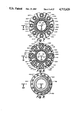
- FIG. 4 is a top plan view of the invention showing the bore of the diverter, taken along line 4--4 of FIG. 2,
- FIG. 5 is a cross-sectional view showing the top of the flexible joint and taken along line 5--5 of FIG. 2,
- FIG. 6 is a cross-sectional view of the hose/stab carrier, taken along line 6--6 of FIG. 2,
- FIG. 7 is a cross-sectional view showing the connection of the stab subs to a retainer plate, taken along line 7--7 of FIG. 2,
- FIG. 8 is a cross-sectional view showing the cylinder assemblies and connector assembly for the lower end of the cylinder assemblies, taken along line 8--8 of FIG. 2,
- FIG. 9 is a cross-sectional view showing the top and bore of the rotation bearing joint, taken along line 9--9 of FIG. 2,
- FIG. 10 is a cross-sectional view showing the gear system of the rotation bearing joint, taken along line 10--10 of FIG. 2,
- FIG. 11 is an elevational cross-sectional view of part of the diverter, housing and flexible joint taken along line 11--11 of FIG. 4,
- FIG. 12 is an elevational cross-sectional view of a diverter lock down dog, taken along line 12--12 of FIG. 4,
- FIG. 13 is an elevational cross-sectional view of the lower flange of the flexible joint, carrier, packer seal assemblies, etc. taken along line 13--13 of FIG. 5,
- FIG. 14 is an elevational cross-sectional view of the lock up dogs, the upper part of the cylinder assemblies and inner and outer barrels, taken along line 14--14 of FIG. 7,
- FIG. 15 is a cross-sectional view of some of the lock-up dogs, taken along line 15--15 of FIG. 14,
- FIG. 16 is an elevational cross-sectional view of one of the lock-up dogs, taken along line 16--16 of FIG. 15,
- FIG. 17 is a view of the air manifold, taken along line 17--17 of FIG. 14,
- FIG. 18 is a cross-sectional view of part of the reaction ring, taken along line 18--18 of FIG. 14,
- FIG. 19 is an elevational cross-sectional view of the lower part of the cylinder assemblies attached to the outer barrel, taken along line 19--19 of FIG. 8,
- FIG. 20 is a plan view of the snubber located at the lower end of the cylinder assemblies, taken along line 20--20 of FIG. 19,
- FIG. 21 is an elevational cross-sectional view of the snubber, taken along line 21--21 of FIG. 20,
- FIG. 22 is an elevational cross-sectional view of the rotation bearing joint, locking and unlocking devices, and gear system taken along line 22--22 of FIG. 9,
- FIG. 23 is an elevational cross-sectional view of one locking/unlocking device shown in FIG. 22,
- FIGS. 24-27 illustrate the steps in landing the upper marine riser package onto the hose/stab carrier first and then finally in the diverter housing
- FIG. 28 is an elevational view of the upper portion of the second embodiment of this invention.
- FIG. 29 is a cross-sectional view taken along line 29--29 of FIG. 28,
- FIG. 30 is a cross-sectional view taken along line 30--30 of FIG. 28,
- FIG. 31 is an elevational, cross-sectional view of part of the diverter, diverter housing, and ball joint taken along line 31--31 of FIG. 29,
- FIG. 32 is an elevational, cross-sectional view of the ball joint extension, locking ring, and packer seal assemblies, etc., taken along line 32--32 of FIG. 30, and
- FIG. 33 is a perspective view of this invention as an addition to the conventional riser tensioning systems on a rig.
- vessel V is a drill ship (although a semi-submersible SS shown in phantom may also be used) and is shown floating on a body of water, such as an ocean.
- the vessel includes a vertical opening or "moon pool" M through its hull near the longitudinal and transverse center of the vessel.
- a derrick Supported on the upper deck of the vessel and approximately centered over the moon pool is a derrick from which the upper end of drill pipe P is supported by a traveling block T.
- the derrick and much of the associated equipment are of a type commonly used in offshore rotary drilling and are not shown in detail.
- Approximately centered in the base of the derrick are a support platform S, a riser handling spider HS, and a rotary table R.
- the drill pipe P passes vertically through aligned openings in the platform and rotary table and is rotated by the rotary table R in a standard manner.
- Anchors may be used to limit the movement of the vessel from its normal position over the well or, in deep water drilling, the vessel may be positioned dynamically.
- a wellhead W is located on the submerged formation in which the hole is being drilled.
- the wellhead includes a base B and several lengths of well casing C extending beneath the wellhead into the well.
- drilling guide lines (not shown) extending between the vessel and the base B are used to guide equipment as it is lowered from the vessel to the wellhead, but in deep water drilling, such equipment is lowered and positioned on the wellhead by sonar, T.V., etc.
- a riser string RS With the wellhead in place on the ocean bottom, a riser string RS, a lower marine riser package LMRP and blowout preventer BOP, are lowered to connect the vessel to the wellhead.
- This riser string is releasably connected at its lower end to the wellhead and is connected at its upper end to the vessel in a manner which will be described below.
- High density drilling fluid from a mud system on the vessel is fed to the well from a pump to a drill bit DB at the bottom of the well and is returned to the sump by passing upwardly around the outside of drill pipe through well casings C, through the wellhead and then upward through the riser string where it is returned to the mud system.
- UMRP upper marine riser package
- the upper marine riser package 10 includes four main components--a diverter D cooperable with a housing DH (FIGS. 2, 4, 11 and 12), a flexible joint FJ (FIGS. 2 and 11), a self-tensioning riser slip joint SJ (FIGS. 2, 5, 6, 7, 8, 13 and 21), and a riser rotation bearing joint RB (FIGS. 2, 9, 10, 22 and 23).
- the self-tensioning riser slip joint SJ, and riser rotation bearing RB can be connected, as a modular unit, to the upper end of the riser string.
- the flexible joint FJ and diverter D are then attached to the self-tensioning slip joint.
- it is then lowered through the rotary table of the rig with the diverter D finally locked in place in the diverter housing DH.
- FIGS. 2, 4 and 11 show the rig sub-structure or supporting structure S of diverter housing DH, attached thereto as by a fixture F, containing the diverter D to which is connected a flexible joint FJ (FIG. 11).
- the flexible joint FJ supports an upper spool 12 (FIGS. 13 and 14) which, in turn, supports: first, a fixed inner barrel 14 (the first part of the slip joint SJ), and second, a moveable outer barrel 16 telescoped over the inner barrel (the second part of the slip joint SJ), by multiple peripheral tensioning cylinder assemblies 20 (FIGS. 2 and 13-19).
- tensioning cylinder assemblies 20 (presently eight in number although the number can vary), have their respective hollow piston rods 22 connected to the upper spool 12 while the respective outer cylinders 24 are connected to the moveable outer barrel 16 by connecting assembly 26 (FIG. 19).
- Double packer seal assemblies 30 (FIGS. 13 and 14) provide an annular seal between the inner barrel and outer barrel and, since the barrels are keyed together by slot and key assembly 32 (FIGS. 14 and 18), rotational torque is transmitted from the inner barrel to the outer barrel through riser rotation bearing joint RB to the riser when the vessel is used to orient the lower stack before landing on wellhead.
- the riser rotation bearing RB joint is equipped with locking/unlocking devices and a gear system assembly 36, which are used to orient the lower riser stack if the vessel is required to maintain the heading to the current or wind during a storm (FIGS. 2, 9, 22 and 23).
- the upper marine riser package 10 is shown connected to the upper riser of riser string RS by a riser connector RC (FIGS. 2 and 22) and the slip joint SJ is held in fully retracted position, as shown in the drawings, by a plurality of outer lock-up dogs 42 located below the upper spool (FIGS. 15 and 16).
- the housing DH is cylindrical, fixed to and extends downwardly through the rig sub-structure S, and is typically provided vents 44 and mud-flow outlets 46.
- the housing is attached to beams of the rig substructure slightly below the rotary table and houses the diverter D.
- the diverter D is typically a cylindrical ring 50 with an inner bore 52 with the operating apparatus therein. Only the ring 50 and bore are shown since the inner apparatus and its function is conventional.
- the outer wall of the cylindrical ring 50 is provided with a landing shoulder 54 which engages a radially inwardly extending landing edge 56, sometimes referred to as a landing profile, on the inner surface of the housing to limit the downward movement of the diverter D.
- a plurality of hydraulically actuated diverter lock-down dogs 60 are located around the outer periphery of the housing, extend through windows 62, and engage a plurality of locking grooves 64 formed on the outer wall of the diverter D to lock the diverter D within the housing DH. All hydraulically actuated lock-down dogs are identical and the cylinders thereof are connected by a pair of hydraulic lines 66 for extension and retraction of the lock-down dogs to an operator controlled pressure system 70 located on the rig and shown schematically as block diagrams in FIG. 3. Similarly connected hydraulically actuated lock dogs are shown in the U.S. Pat. No. 4,057,267 of Jones to which reference is made.
- the function and operation of the diverter D is conventional. It is activated to vent uncontrolled formation gas out a line connected to the vent 44. This connection may also be used as a flushing line. Return mud flows out a line connected to outlet 46.
- Attached to the lower end of the diverter D is a flexible joint FJ.
- the lower surface of the diverter D is provided with a plurality of threaded bores to receive the threaded ends of suitable bolts 72 (one shown) extending through a radially extending attaching flange 74 forming part of the flexible joint FJ.
- the flexible joint FJ comprises two main body members, an upper body member 76 and a lower body member 80 which is telescoped within the upper body member 76 and separated therefrom to accommodate an elastomeric bearing assembly 82 and an elastomeric seal assembly 84.
- the upper body member 76 is provided with an axial bore, the diameter of which is substantially coextensive with the inner bore of the diverter D and is provided with a radially narrow neck 86 immediately below the flange 74 to accommodate the heads of the bolts 72 attaching the flange 74 to the diverter D.
- the upper body member is also provided with a cylindrical downwardly opening housing 90 with its inner wall spaced from the lower body member 80 and encloses the bearing assembly 82 and seal assembly 84.
- the outer diameter of the outer wall of the housing 90 is substantially the same as the outer diameter of the flange 74, and has an outer bearing ring 92 suitably attached to its lower end as by a plurality of threaded bolts 94.
- the radially inner edge 96 of the bearing ring 92 is spaced from the lower body member 80 to provide a clearance for tilting movement of the lower body member relative to the upper body member 76.
- the bearing assembly 82 which includes the bearing ring 92 and the manner of operatively connecting the bearing assembly to the two main body members 76 and 80, are fully taught in the U.S. Pat. No. 4,068,868, supra, to which reference is made for more complete information concerning this bearing assembly 82.
- the sole difference between the bearing assembly of this invention and that discussed in the Patent is in the increased amount of loading on the bearing assembly in this invention. However, it is within the skill of those in the art to select the size, shape and type of materials to accommodate this increased load using the teaching of the Patent. See also the use of an elastomeric bearing in the U.S. Pat. No. 4,391,554 to Jones to which reference is made.
- seal assembly 84 located on the upper end of the lower body member 80 is located on the upper end of the lower body member 80 to prevent leakage from the interior of the flexible joint into the cavity within the housing 90.
- This seal assembly 84 permits relative flexing or tilting in all directions while maintaining the integrity of the seal.
- U.S. Pat. No. 4,068,868, supra discusses a similar seal assembly and the manner of operatively connecting the seal to the two main body members 76 and 80, in detail.
- the lower body member 80 (shown in two pieces welded together in FIG. 11) extends downwardly beyond the cylindrical housing 90 and terminates in a lower radially outwardly extending flange 100 (FIG. 13) which is bored and affixed by suitable bolt assemblies 102 to a flange 104 comprising the upper end of the upper spool 12.
- the upper spool 12 is part of the self-tensioning slip joint SJ supporting the inner and outer barrels and tensioning cylinders, the bearing joint RB and the connected risers.
- the upper spool 12 is a relatively long, relatively thick cylindrical ring, with an outer diameter substantially equal to the diameter of the diverter D.
- the outer periphery of the ring is configured to form the aforementioned flange 104 and to also provide a spider landing shoulder 106 to aid in making up the package. This make up procedure will be discussed in more detail later.
- the inner bore of the spool is provided with a counterbore 110 which provides space for a landing ring 112 (inner barrel hanger).
- This landing ring 112 is locked into the inner barrel by a split ring 114 trapped in oppositely facing grooves on the ring and upper end of the inner barrel 14 and also contains a plurality of screws 116 (only one being shown) which engage threaded holes in the landing ring 112 and screwed to engage the mating slots in the upper end of the inner barrel 14, thus preventing the inner barrel from rotation or, as designed, making the inner barrel to rotate with the rig.
- the radially outer periphery of the landing ring is locked to the upper spool 12 by a key/slot and landing arrangement 120 and thus is keyed to the inner barrel.
- An insert piece 122 lands on the top of the inner barrel to provide an inner diameter approximately coextensive with the inner diameter of the inner barrel and bore of the flexible joint FJ.
- This insert extends upwardly into the bore of the lower body member 80 of the flexible joint and straddles the joint between the flange 100 and the flange 104 to provide a sealed bore.
- the insert 122 is held against movement by a split ring 124 disposed within oppositely facing grooves in the flange 100 and insert 122 and is locked in place by a second split locking wedge 126 and a resilient O-ring 130 disposed in the same groove in the insert.
- the O-ring pressures the locking wedge 126 upwardly behind the split ring 124, to retain the same position, but permits easy removal by withdrawal of the resilient O-ring 130.
- the lower end of the insert 122 has a shoulder 132 which engages the top edge of the inner barrel, and thus serves to restrain the inner barrel and lock ring 112 from upward movement.
- Suitable sealing means such as O-ring seals, are provided to prevent leakage out between the flanges and elsewhere.
- a cylindrical carrier 140 Surrounding the upper spool 12 is a cylindrical carrier 140 comprising a wall which extends from approximately the lower end of the upper spool 12 to approximately the upper end of the upper spool 12.
- Approximately the lower half portion 142 of the carrier is thicker than the remainder of the ring and is a sliding fit with the outer surface of the upper spool.
- the mid portion 144 of the carrier has a larger radial inner diameter than that of the lower portion and extends upwardly to terminate in a upwardly facing funnel 146.
- the mid portion 144 joins the lower end of the diverter housing DH and the funnel 146 aids in guiding the carrier around the diverter housing DH.
- a drain passage 148 is located between the lower and mid portions of the carrier.
- This carrier 140 has thus two positions--a stored position attached to the diverter housing DH, and an operating position surrounding the upper spool.
- the two positions of this carrier are part of the makeup procedure of the package which will be described later.
- the lower end of the carrier 140 also has an inner landing profile 150 which is engaged by a radial shoulder 152 on the upper spool 12 when the upper spool is landed within the carrier as shown in FIG. 13.
- each locking dog moves in and out through a window 156 in the carrier to engage and disengage mating grooves 160 (FIGS. 2 and 11) in the outer periphery of the housing DH and the cylinder 158 is connected by a pair of lines 162 to the same operator controlled system 70 located on the rig.
- these locking dogs are similar in function and operation to the previously described locking dogs 60.
- a plurality of hose/stab assemblies 164 positioned on a clamping ring 166.
- the clamping ring 166 is formed in halves and bolted together to clamp around the outer periphery of the carrier 140 and is positioned thereon by a circular key and slot arrangement 170.
- the clamping ring is provided with radially outwardly extending cavities 172, also formed in two halves bolted together and welded to the clamping ring to engage the outer periphery of the housing 174 of the hose/stab assemblies 164.
- each hose/stab assembly 164 has a hollow stab (tubing) 176 moveable radially inwardly and outwardly through windows 180 in the clamping ring 166 and carrier 140, respectively, and into and out of a suitable horizontal port 182 in the upper spool 12.
- Windows 180 are larger than the outer diameter of the stabs 176 to allow the stabs to "float" to compensate for tolerance variations in the carrier, clamping ring and the port 182.
- the stab is a hollow rod integral to a piston 184 reciprocable in a chamber in response to hydraulic fluid entering the chamber on either side of the piston from a pair of hydraulic lines 186 connected to a chamber and to a source of fluid under pressure.
- the chamber is also connected to hydraulic fluid under pressure through a line 190 connected to a coupling 192 located on the end of the housing. This latter fluid under pressure enters the chamber, passes through the piston via the hollow tube and into the port 182 of the upper spool 12. So that the piston will not be responsive to this latter fluid pressure, the piston is hydraulically balanced and is thus responsive only to the fluid in the two lines 186 for movement of the stab in and out of the upper spool.
- the source of hydraulic fluid under pressure for lines 186 and 190 is the same operator controlled pressure system 70, supra.
- the mid portion 144 of the carrier 140 is also provided with a plurality of hydraulically actuated locking dogs 194 (FIGS. 2 and 6) interspersed between the hose/stab assemblies (four of such locking dogs being shown, although their number could vary) to engage a suitable groove 196 (FIG. 13) in the upper spool 12 to lock the carrier onto the upper spool when the carrier is released from the diverter housing, so that the dynamic load of the carrier is not imposed on the hydraulic stabs 176.
- a suitable groove 196 FIG. 13
- the hydraulic apparatus for actuating these locking dogs 194 is the same as the previously described locking dogs and is connected by a pair of hydraulic lines 198 to the operator controlled pressure system 70. Therefore, no further description is deemed necessary.
- the locking dogs 154 located on the mid portion of the rig are used to lock the carrier onto the diverter housing DH before and when the upper spool lands in the carrier.
- the four locking dogs 194 on the lower portion of the carrier are activated to lock the carrier onto the upper spool.
- the hollow stabs 176 are pressured to stab into their corresponding ports.
- the next step is to retract the upper locking dogs 154 from the diverter housing DH allowing the carrier and hose/stab assemblies to lower with the upper spool until the diverter itself has landed on the diverter landing profile 56. This is the position of the upper spool as shown in FIG. 13.
- the horizontal ports 182 on the upper spool 12 and their stabs 176 communicate with vertical ports 200 on the upper spool 12 which in turn are connected to the hollow piston rods 22 of the tensioning cylinder assemblies 20 forming part of the self-tensioning slip joint SJ.
- These tensioning cylinder assemblies 20 and how they are attached and operate in the package will now be described. It is understood, of course, that the length of the cylinder assemblies is commensurate with the amount of vertical movement due to the heave of the vessel during operation.
- the lower end of the inner bore of the upper spool 12 is counterbored and threaded as at 202 to receive an externally threaded inner sleeve 204, which has an inner diameter coextensive with the inner diameter of the upper spool and which telescopes over the outer diameter of the outer barrel 16 to accommodate the outer barrel 16.
- This sleeve 204 is provided with an upwardly facing ledge 206 formed by reducing the outer wall of the sleeve.
- a stab sub supporting plate 210 (FIGS. 7 and 13) seats on this ledge and supports cylindrical hollow stab subs 212 (eight in number although their number may vary), as well as the hollow piston rod 22 coupled thereto.
- the sleeve 204, the stab sub support plate 210 and the supporting ribs 214 are an assembled part which is subsequently welded to the low end of the upper spool to form a rigid support for the cylinder assemblies. Since all stab subs are identical, only one will be described.
- the stab sub 212 has a smooth outer surface at its top end 216 and is insertable in the vertical port 200 (one shown in FIG. 13). Suitable O-ring seals are positioned in the port 200 to form a liquid tight connection.
- the stab sub 212 is internally threaded at its lower end, as at 220 (FIG. 14), to engage mating external threads on the upper end of the hollow piston rod 22.
- the stab sub is also provided with external threads 222 at its mid portion on which a clamping nut 224 is threaded.
- the clamping nut 224 engages the upper surface of the stab sub supporting plate 210 and, together with a stop (ledge) 226 on the stab sub, hold the stab subs in place after having been inserted into the vertical bore 200 in the upper spool 12.
- the stab sub supporting ring 210 has a radially opening groove 230 (FIG. 7) to allow the stab subs to be inserted and removed from the stab sub support plate 210.
- the lower end of the tensioning cylinder assemblies 20 are removeable at the connection assembly 26 also for this purpose.
- the stab sub/hollow piston rod 22 can be lowered to allow removal of the stab sub from the upper spool, and the stab sub, together with the cylinder assemblies 20, can be pulled outwardly for removal and repair.
- Making up the connection of the cylinder assembly 20 and stab sub is a reverse procedure. The disconnection of the cylinder assembly 20 from the connecting assembly 26 will be described later.
- the outer barrel lock-up dogs 42 are spaced peripherally between the stab subs and located below the stab supporting plate 210. Their purpose is to hold the outer barrel in position until the cylinder assemblies 20 are pressurized. Since all eight lock-up dogs 42 are identical, only one will be described (FIGS. 15 and 16). Thus, each dog 42 is moveable radially in and out of engagement with a plurality of grooves 232 formed in the outer barrel through a window 234 in the sleeve 204. Each dog 42 is coupled by a retainer head and groove assembly 236 to an actuating screw 240 threaded for rotation within a threaded bore in a support plate 242 fixed to the sleeve 204.
- the screw is rotated by a shaft 244 by an air motor 246 driving a gear box 248 to move the dog 42 radially in and out of engagement with grooves 232.
- the air motor/gear reducer combination is suitably fixed to the support plate 242 and air under pressure is supplied to the motor via air supply line 250 connected to the operator controlled pressure system 70 on the rig. Exhaust 252 is part of the motor.
- a stabilizing ring 260 clamped to the outer barrel 16 to hold (centralize) the cylinder assemblies 20 relative to the outer barrel.
- This stabilizing ring 260 is formed in halves with radial flanges (not shown) bolted together and is provided with radially opening slots 262 to allow the cylinder assemblies 20 to be removed for repair and replacement.
- the stabilizing ring 260 is similar to the stab sub supporting plate 210 of FIG. 7 and thus is not shown in plan view and, again, since all eight cylinder assemblies 20 are identical, only one will be described.
- each outer cylinder 24 of each cylinder assembly 20 is closed at its upper end by a centrally apertured cylinder head 264 inserted within the cylinder 24 and held in place by the combination of a positioning ring 266 and a bushing 270, which engages a shoulder on the cylinder head and which is fixed thereto by set screws 272.
- Both the inner wall of the cylinder, the cylinder head, and the bushing have semi-circular grooves to collectively receive the positioning ring 266.
- a plurality of resilient seals in the aperture of the cylinder sealingly engage the piston rod and allow axial movement therein. As shown in FIGS.
- a slideable piston 274 is fixed to the lower end of the piston rod 22 and provided with resilient seals which sealingly engage the inner wall of the cylinder in a conventional manner.
- a snubber 280 Suitably attached to the top of the piston, as by bolts 276 is a snubber 280.
- This snubber 280 is a barrel-like member, having a conically formed outer surface 282 which will be received in the downwardly facing hollow cup-like area 284 of the cylinder head 264. The snubber and cup-like area will cushion the fall of the cylinder head if the cylinder assemblies were to lose hydraulic pressure at any time.
- the piston is also provided with radial passages 286 which communicate with vertical passages 290 in the snubber. Fluid from the operator controlled pressure system 70 communicated through the upper spool, through the hollow piston rod and through passages 286 and 290 which open into the upper chamber formed by the piston, cylinder wall and cylinder head.
- the lower end of the cylinder assembly is closed in a manner similar to the manner in which the cylinder head is attached, that is, ring 292, having a central aperture 294, is inserted in the cylinder, is held against a positioning ring 296 by an internally threaded extension sub or cap 300 which is bolted to the ring 292 and has a ledge 418 which engages the end of the cylinder. Suitable grooves in the ring 292, the extension sub 300, and the cylinder wall hold the positioning ring in place.
- the extension sub 300 has a reduced portion which is externally threaded as at 304 and is long enough to extend beyond support plate 306, formed as an integral part of the outer barrel as a forged ring welded to the outer barrel.
- This forged ring is part of the previously mentioned connecting assembly 26 and is braced for strength by a plurality of strengthening ribs 310.
- the plate 306 is provided with radially outwardly open slots 312 (FIG. 8) to allow insertion and threaded extension sub 300.
- a retainer head 314 beneath the plate 306 cooperates with a nut 316 which is rotated downward to fasten the extension sub 300 to the support plate.
- the retainer head 314 seats in the counterbore 320 in the lower face of the support plate, thus securing itself and the extension sub on the plate.
- the nut 316 is threaded upwardly and then, the nut 224 on the stab sub 212 at the upper end of the assembly is also threaded upwardly allowing the stab sub to drop clear of the port so that the assembly can be maneuvered out through the slots of the upper and lower support plates.
- Both the ring 292 and the extension sub 300 are internally axially bored and connected to a pair of L-couplings 322 which are connected to a hose 324 which extends upwardly between adjacent cylinder assemblies 20.
- the upper end of the hose 324 (FIGS. 2, 16 and 17) is connected to a hollow ring manifold 326 located about the cylinder assemblies and below the lock-up dogs 42.
- This manifold surrounds the outer barrel and is connected in any suitable manner as by bolting to the stabilizing ring 260.
- the manifold also has large exhaust lines 330 connected by hoses to the rig.
- the double packer seal assemblies 30, providing the annular seal between the inner and outer barrels are located in the same vertical position as the upper spool and its extension.
- On top of the outer barrel 16 is a hollow, cylindrical packer gland 340 which houses the double packer seal asemblies 30.
- the packer gland 340 is attached to a radial flange 342 on the top end of the outer barrel by bolts 344 (FIG. 14).
- a stepped bearing ring 346 on the lower end of the lower packer seal 350 lands on a stepped ledge 352 formed on the packer gland.
- the upper end of the lower packer seal 350 is provided with a second bearing ring 354 having a plurality of J-slots 356 (with only the vertical groove of only one J-slot being shown) to receive a pin 360 on still another bearing ring 362 which partly extends into the bearing ring 354.
- the pin in the J-slot 356 locks the two rings together during installation and also against relative rotation, but allows the two rings to be separated if necessary.
- the bearing ring 362 belongs to the upper packer seal 364. Attached to the upper end of the upper packer seal 364 is a fourth bearing ring 366, identical to the bearing ring 354.
- a lockdown ring 370 has external threads 372 to engage internal threads on the upper end of the packer gland and has a plurality of J-slots 374 (again, only one being shown) by which a running tool can rotate this lockdown ring 370, and thread the lockdown ring into the outer barrel to hold the double packer seal assembly in place and to force expansion of both upper and lower packer elements. This same running tool can be used to retrieve replacement since all J-slots are identical.
- Either one of the double packer seals can be pressured from behind against the inner barrel by air under pressure from a suitable source.
- the packer gland is provided with two passages 380 and 382 extending from below lock-up dogs 42 to the packer seals.
- Passage 380 extends to the middle of the lower packer element 342 and the other passage 382 extends to the middle of the upper packer element 354. Both passages extend through an enlarged radius 384 on the outer barrel and through the packer gland 340 (passage 380 more clearly shown in FIG.
- Drilling fluid will enter the space between the inner and outer barrels, by reason of apertures 392 (FIG. 19) in the inner barrel 16 during operation, thus helping to lubricate the packing elements.
- the key assembly comprises an elongated keys 400 on the outer barrel 16 and which extend the full length of the stroke of the slip joint and are attached to the outer barrel by plug wells 402 (FIGS. 14, 16 and 18). These keys 400 slide within key slot 404 formed in the inner barrel shoe 406 (FIG. 19) and also in a reaction ring 410 (FIGS. 14 and 18).
- the reaction ring on inner barrel also serves as a stopper for the slip joint when it comes in contact with the lower ledge 412 (FIG. 16) of the packer gland. Since the two barrels are keyed together, the aforementioned riser rotation bearing joint RB is appropriate to transmit torque from the outer barrel to the inner barrel due to rig rotation. This riser rotation bearing joint RB will now be described.
- the riser rotation bearing RB comprises two telescoped tubular body members 420 and 422.
- the upper tubular body member 420 has a reduced portion which is welded to the outer barrel 16 and which terminates in a radial flange 424.
- An outer cup-like housing 426 is attached by bolts 430 (one shown) to the bottom of the flange.
- the outer wall of the housing 426 is spaced from the lower tubular body member 422 and terminates in a radially inwardly extending wall 432 and a barrel extension 434 which engages the outer lower body member in rotatable relationship.
- Wall 426 defines an oil filled cavity 436 which houses a spherical roller thrust bearing assembly 440.
- the upper end portion of the lower tubular body member is reduced as at 442 and is telescoped within a counterbore 444 in the upper tubular body member 420.
- a suitable low friction ring bearing 446, a thrust spacer or cushion ring 450, and suitable seals 452 provide free fluid tight rotation between the two tubular body members.
- the lower tubular body member is provided with a split ring 454 located in a circumferential groove 456 in the lower tubular body member and bolted as at 460 to the top race of the bearing assembly.
- the split ring 454 and bolt 460 retain the spherical roller bearings, bearing races, etc., of the spherical roller thrust bearing assembly 440 in place to operatively function, as such, between the upper and lower tubular body members.
- Suitable rotary seals 462 between the barrel 434 and lower tubular body member provide a fluid tight relationship between the housing and lower tubular body member.
- the assembly comprising the locking/unlocking devices and gear system 36 are located below the riser rotation bearing joint RB and is used to orient the lower riser stack if the vessel is required to maintain heading to the current or wind during a storm.
- a second outer housing 464 whose outer wall is coextensive with the outer wall of the housing 424 of the bearing joint, is attached to the housing 426 by bolts 466.
- This housing encloses the loading/unloading devices and part of the gear system. Since there are a plurality of these devices located circumferentially of the lower tubular body member, only one is described and shown.
- FIGS. 22 and 23 it can be seen to comprise a locking pin 470 moved into and out of engagement within a suitable bore 472 in the lower tubular body member by a hydraulic cylinder 474.
- Its piston 476 connected to the pin 470 by a retainer head and groove arrangement 480, is biased by a spring 482 outwardly from the bore 472.
- the cylinder is hydraulically connected by a suitable hydraulic line 484 to the operator controlled pressure system 70 on the rig.
- the spring 482 urges the locking pin 470 out of engagement with the bore 472 and the hydraulic pressure is used to urge the lock pin into the bore.
- a pin 486 signals the position of the locking pin 470.
- Attached to the lower radially inward wall 490 of the housing below the locking/unlocking devices is the gear system of assembly 36 which comprises a pair of hydraulic motors 492 (FIGS. 10 and 22).
- Each motor shaft 494 drives a pinion gear 496 which meshes with a ring gear 500 fixedly attached to the lower tubular body member 422 by drive keys 502 so that rotation of the motor shafts rotate the tubular member 422 relative to the upper tubular body member 420 when the lock pins 470 are withdrawn from the tubular body member.
- Each motor is hydraulically connected by branch lines 504 to a main line 506 to connect the operator controlled pressure system 70. Rotation of the lower tubular body member is incremental depending on the circumferential spacing of the locking bores 472.
- FIGS. 2, 13 and 16 illustrate the lock-up dogs 46, air pressure actuated and holding the slip joint SJ in lock-up position as it would be during installation or retrieval. Attention is now directed to FIGS. 24-27 for the steps in making up the upper marine riser package.
- FIG. 24 illustrates the carrier 140 locked onto the diverter housing DH by lock-up dogs 154.
- the slip joint SJ and riser rotation bearing RB were first made up, connected to the riser connector RC (FIGS. 2 and 22), and held by the marine riser handling spider HS engaging the spider landing shoulder 106 on the upper spool 12 (FIG. 13). At this time, the carrier 140 is still locked on the diverter housing DH.
- the diverter D and flex joint FJ are brought over and attached to the upper spool with mating flanges 100, 104.
- the upper spool is then freed of the riser handling spider HS and lowered through the rotary table until the landing surface 152 on the upper spool orients and lands on the profile 150 of the carrier 140 (FIG. 25).
- the locking dogs 194 are hydraulically actuated to lock the upper spool 12 onto the carrier 140. This is followed by extending the stab subs 176 into their respective ports through hydraulic actuation of the lines 186.
- the locking dogs 154 are then retracted and the entire package is lowered until the diverter landing surface 54 lands on the profile 56 on the diverter housing (FIG.
- the diverter lock-up dogs 60 are then actuated to lock the diverter D in the diverter housing DH. Then, for operation of the self-tensioning slip joint SJ, fluid pressure is applied to the cylinder assemblies 20 to ensure that the slip joint SJ would not drop the full stroke of the piston rods. The applied pressure will be high enough to apply greater tension on the riser string than for normal operation and then the control operator will release the lock-up dogs 42 by air pressure releasing the outer barrel to allow the outer barrel to descend gently by bleeding pressure from the cylinder asemblies till the BOP stack lands and locks on the wellhead.
- the derrick will be used to support some of the load of the riser string while the control operator releases the lock up dogs 42 and bleeds pressure from the cylinder assemblies to allow the outer barrel to descend gently. Thereafter, the slip joint is set and tensioned at mid stroke, compensating for the rise and fall of the vessel due to tides, waves, and the like to keep the riser string in constant tension.
- the riser string RS is disconnected at the wellhead and additional fluid pressure is then applied to the cylinder assemblies 20 to raise the outer barrel to the position as shown in FIG. 26 where the lock-up dogs 42 can again lock the outer barrel in position.
- the entire package, including the carrier 140 is raised by handling sub until the locking dogs 154 are level with the grooves 160 on the diverter housing, at which time the locking dogs 154 are pressured into the grooves.
- the diverter and flexible joint can then be removed separately or together from the upper housing spool 12. Removal of the flexible joint also withdraws the insert 122.
- a running tool may be inserted into the bore of the inner barrel (the insert 122 having been removed) where it engages a downwardly facing surface 510 (FIG. 13).
- This downwardly facing surface was previously used to assemble the inner barrel within the outer barrel.
- the inner barrel, together with its hanger 112 are hauled through the upper spool to rest the inner barrel hanger on handling spider.
- the inner barrel is disconnected from its hanger by removing the screws 116 and the split ring 114. Once the inner barrel is freed from it hanger, it is lowered, to free stand on the ledge 512 of outer barrel (FIG. 19).
- the top of the inner barrel is now below the packer seals, giving that area an open hole.
- a J-tool could then engage the J-slots 374 on the top ring 370 of the packer assembly and rotate the top ring so that ring 370 can be removed. Use the same J-tool to retrieve the first packer element or together with the second packer element for repair and replacement.
- FIGS. 28-32 there is shown, in part, another embodiment of the upper marine riser package, identified as 10A.
- the flexible joint FJ is replaced by a ball joint BJ and modifications are made in the diverter housing DH to the upper spool 12.
- the remainder of the upper marine riser package remains the same.
- the suffix A will be added to those parts which are modified but perform a similar function as those parts described previously.
- Those parts in this embodiment which are exactly the same in both embodiments will be given the same reference numeral.
- the diverter housing DHA comprises an inner cylindrical diverter housing 520, a support frame or ring 522 spaced therefrom, a cylindrical ball joint housing 524 and vent and mud flow connections 44 and 46.
- the ball joint housing 524 is mounted to the rig platform S by a bolt/flange arrangement as previously described for the first embodiment.
- the inner wall of the diverter housing 520 is provided with an upwardly facing landing profile 56 for the landing surface 54 on the diverter outer wall.
- the upper end of the diverter housing 520 is connected to a support frame 522 by a plurality of radially oriented gussets 526.
- the support frame has a downwardly facing landing surface 530 which engages an upwardly facing profile 532 on the ball joint housing 524 so that the support frame 522 supports the diverter housing.
- the diverter housing is locked by a plurality of hydraulically actuated lock dogs 534 extending through the ball joint housing and engaging an upwardly facing ledge 536 on the support frame.
- the hydraulic actuators for the lock down dogs 534 are similar to actuators for the locking dogs 154 shown in FIG. 13.
- connections 44A and 46A are provided for the diversion of gas and drilling mud through the vents 44 and 46 similar to that of FIGS. 2 and 11.
- Suitable seals such as metallic seals 540 and O-ring seals, prevent leakage from the outlets.
- the diverter is locked in its housing by lockdown dogs 60 which engage grooves 64 in the diverter outer wall in a manner similar to that previously described.
- the lower end of the ball joint housing 524 is thickened so that its inner surface extends radially inwardly to form a socket 542.
- a replaceable bearing insert 546 coated with TFE based material for low friction is provided between the main ball body 550 and the socket 542.
- the main ball body 550 is hemispherical on both its inner and outer surfaces 552 and 554.
- a radially smaller hemispherical segment 556 engages the inner surface 554 and has a cylindrical extension 560 extending upwardly within the diverter housing 520.
- the diverter housing has an enlarged radius 562 to accommodate the cylindrical extension so that the inner surface of the remainder of the diverter housing and the inner surface of the extension are radially equal to present a smooth bore for the diverter.
- the smaller hemispherical segment 556 allows tilting action of the main ball body in its socket since the hemispherical segment and its extension are fixed vertically by the diverter housing and rotationally by a anti-rotation pin 564 within a relatively long vertical slot 566 in the diverter housing. Any wear of the bearing inserts 546, the main ball joint segment 550, or on the surface of the hemispherical segment 556 will be accommodated by downward movement of the segment 556 and its extension 560.
- Suitable sealing means such as O-ring seals, are disposed in the surface of the hemispherical segment and between the extension and inner wall of the enlarged radius 562 to seal against leakage through the ball joint.
- a ring 570 is fixed to the top surface of the main ball segment, as by bolts 572, and has a radially extending anti-rotation pin 574 threaded in the ring and extending therefrom into a vertical slot 576 in the outer cylinder to prevent rotational movement, yet allow tilting movement of the ball joint on two axes.
- the main ball segment 550 has a cylindrical extension 580 directed downwardly and shown integral therewith (FIG. 32). Near its lower end, the extension 580 has a landing profile 150 on its inner wall which engages a shoulder 152 on the upper spool 12A when the upper spool 12A is oriented and landed in the extension.
- the upper spool 12A serves the same functions as were previously described in the first embodiment, except that the tension load is now transmitted through the ball joint housing 524 to the rig structure, and not through the diverter housing 520. The sequence of installation is also different.
- the upper large ball joint is, in this case, installed together with hose/stab assembly 164 as a ready package to receive the self-tensioning slip joint SJ.
- the upper spool 12A is part of the self-tensioning slip joint SJ supporting the inner and outer barrels 14 and 16, the tensioning cylinder assemblies 20, the bearing joint RB and the connected risers.
- a spool lock-down ring 582 is landed in the ball joint segment extension 580, the inner barrel lock-down dogs 194 are then actuated through windows in the extension to engage mating grooves in the lock-down ring 582, except that the lock-down dogs 194 engage the lock-down ring instead of the upper spool itself.
- These dogs and their hydraulic actuators are the same type as those described in the first embodiment and need not be described further.
- This lock-down ring 582 restrains the upper spool from upward movement and its inner wall is provided with gussets 584 to support an inner ring 586.
- a funnel 590 welded to the two ring 582 and 586 seals off the areas below the diverter by means of an O-ring seal in a ring 610 attached to the outer periphery of the funnel.
- the inner ring 586 has a thickened portion 592 which extends radially inwardly over an inner barrel hanger 594, thus preventing the inner barrel from upward movement during operation. More precisely, inner ring 586 engages the upper edge of the inner barrel hanger 594 while the latter has a reduced portion forming a downwardly facing surface 596 which engages the top end of the inner barrel.
- the inside diameters of the ring 586 and the inner barrel hanger 594 coincide with the inner diameter of the inner barrel.
- the inner ring 586 is provided with a J-slot 600 with a long upwardly extending slot opening to receive a pin 602 in a wear bushing 604.
- Wear bushing 604 lands within the inner barrel and engages a landing shoulder 606 on the inner ring 586. Suitable seals such as O-ring seals are installed to prevent leakage.
- J-slots 612 are provided in the vertical portion of the wear bushing 604 for independent removal of the bushing with a running tool.
- the upper portion of the upper spool 12A is bored and provided with internal threads 656 to engage mating threads on a running tool for running and retrieving of the self-tensioning slip joint through the rotary table. Retrieving would take place after removal of the wear bushing 604 and lockdown ring 582.
- the inner barrel hanger 594 is prevented from rotation by vertical pins 616 in the upper spool extending through a relatively thin ring 620 forming the lower portion of the inner barrel hanger.
- This ring 620 rests on the upper spool and is attached to a vertical cylindrical ring 622 which is welded to the main ring 624 of the hanger.
- This main ring 624 has a plurality of threaded bores into which bolts 626 are threaded to engage bores 630 in the inner barrel to hold the latter relative to the hanger.
- a vertical cylindrical extension 632 on the ring provides the downwardly facing surface 596 which engages the upper edge of the inner barrel to lock the inner barrel against upward movement.
- the lower end of the bore of the upper spool is counterbored and threaded, as at 202, to receive the threaded inner sleeve 204.
- This sleeve and the slip joint are the same as previously described and need not be further described at this point.
- the riser string is disconnected at the wellhead and fluid pressure is then applied to the cylinder assemblies 20 to raise the outer barrel to the position where, as before, the lock up dogs 60 can again lock the outer barrel 16 in retracted position. In this position, the diverter lock down dogs 60 are retracted so that the diverter D can be withdrawn from the housing DHA.
- the upper spool 12A, the packer seal assemblies 30, and the inner and outer barrels 14 and 16 may be retrieved through the diverter housing 520. If it is required, the diverter housing 522 itself with the hemispherical segment 556 may be withdrawn, with or without the diverter remaining inside, simply by retracting those locking dogs in the locking device 534.
- the inner spool lockdown dogs 194 will be retracted and a running tool engages the J-slots 612 in the wear bushing to withdraw the wear bushing and lockdown block 582 exposing the threads 656 on the upper spool.
- a running tool will engage the threads 656 and withdraw the upper spool, together with the self-tensioning slip joint and riser string.
- the main ball segment 550 can be removed for service or for replacing the bearing insert 546.
- the diverter and the lock down ring 582 and wear bushing 604 must first be removed.
- a tool is lowered to engage the surface 596 on the inner barrel and retrieve the inner barrel hanger 594 onto the handling spider. While the inner barrel is partially supported by the retrieving tool, the bolts 626 are removed from the slots 630 on the inner barrel separating the hanger from the inner barrel which is then lowered down to free-stand inside the outer barrel below the packer seal assembly.
- the J-slots in the upper stepped ring of the packer seal assembly is exposed.
- a running tool can engage these J-slots, rotate the upper rings and remove the packer seal assemblies.
- the marine package is easily made up and easily retrievable for repair and maintenance in a manner similar to the repair and maintenance of the first embodiment, except for the details required because of the difference between the ball joint and the flex joint.
- the upper marine riser package 10 or 10A may be used to rid the rig of the equipment necessary to operate the conventional riser tensioning system or, since the package is completely, or substantially completely, below the platform of the rig, it can be used as an addition to the conventional riser tensioning system to provide greater load capabilities for the tensioning system.
- FIG. 33 shows the derrick, traveling block T and support platforms previously referred to in FIG. 1.
- the traveling block T is provided with a motion compensator unit 640 and accumulator 642 for vessel motion compensation for the drill pipe P (not shown in this Figure).
- the riser tensioner units 644, idler sheaves 646, operator controlled pressure system 70 to control fluid supply unit 650, air dryer/compressor unit 652 and air bottle assembly 654 for the conventional riser system are shown.
- the wire rope 656 for connecting the conventional riser tensioning system is shown connected to a tensioning ring 660 in the conventional manner.
- the system is conventional; however, also shown is the upper marine riser package 10 which is used in conjunction with the conventional riser tensioning system. Since both are connected to the same operator control panel 70 and to the same fluid and air supply system the two are compatible to increase the load capabilities of the rig for deeper and deeper water operations.
- the cylinder assemblies having hollow piston rods as a means of communicating fluid pressure to the cylinder assembly chambers
Landscapes
- Engineering & Computer Science (AREA)
- Geology (AREA)
- Life Sciences & Earth Sciences (AREA)
- Mining & Mineral Resources (AREA)
- Physics & Mathematics (AREA)
- Environmental & Geological Engineering (AREA)
- Fluid Mechanics (AREA)
- Mechanical Engineering (AREA)
- General Life Sciences & Earth Sciences (AREA)
- Geochemistry & Mineralogy (AREA)
- Earth Drilling (AREA)
- Medicines Containing Material From Animals Or Micro-Organisms (AREA)
- Magnetic Resonance Imaging Apparatus (AREA)
Abstract
Description
Claims (51)
Priority Applications (4)
| Application Number | Priority Date | Filing Date | Title |
|---|---|---|---|
| US06/696,823 US4712620A (en) | 1985-01-31 | 1985-01-31 | Upper marine riser package |
| GB8601345A GB2170534B (en) | 1985-01-31 | 1986-01-21 | Upper marine riser package |
| NO860314A NO172302C (en) | 1985-01-31 | 1986-01-29 | STIG ROER SYSTEM |
| FR868601290A FR2584449B1 (en) | 1985-01-31 | 1986-01-30 | UPPER ASSEMBLY FOR MARINE EXTENSION TUBE, SELF-TENSIONING SLIDING JOINT, ROTATION BEARING JOINT, TUBULAR CONDUIT, VESSEL, AND METHOD OF USING THE SAME |
Applications Claiming Priority (1)
| Application Number | Priority Date | Filing Date | Title |
|---|---|---|---|
| US06/696,823 US4712620A (en) | 1985-01-31 | 1985-01-31 | Upper marine riser package |
Publications (1)
| Publication Number | Publication Date |
|---|---|
| US4712620A true US4712620A (en) | 1987-12-15 |
Family
ID=24798698
Family Applications (1)
| Application Number | Title | Priority Date | Filing Date |
|---|---|---|---|
| US06/696,823 Expired - Lifetime US4712620A (en) | 1985-01-31 | 1985-01-31 | Upper marine riser package |
Country Status (4)
| Country | Link |
|---|---|
| US (1) | US4712620A (en) |
| FR (1) | FR2584449B1 (en) |
| GB (1) | GB2170534B (en) |
| NO (1) | NO172302C (en) |
Cited By (77)
| Publication number | Priority date | Publication date | Assignee | Title |
|---|---|---|---|---|
| US4934871A (en) * | 1988-12-19 | 1990-06-19 | Atlantic Richfield Company | Offshore well support system |
| US5582438A (en) * | 1994-12-21 | 1996-12-10 | Wilkins; Robert L. | Lateral connector for tube assembly |
| US5660241A (en) * | 1995-12-20 | 1997-08-26 | Dowell, A Division Of Schlumberger Technology Corporation | Pressure compensated weight on bit shock sub for a wellbore drilling tool |
| US5727630A (en) * | 1996-08-09 | 1998-03-17 | Abb Vetco Gray Inc. | Telescopic joint control line system |
| US5800063A (en) * | 1992-03-03 | 1998-09-01 | Stanley; Lloyd | Hydraulic oil well pump drive system |
| US5875848A (en) * | 1997-04-10 | 1999-03-02 | Reading & Bates Development Co. | Weight management system and method for marine drilling riser |
| US5881815A (en) * | 1995-11-29 | 1999-03-16 | Deep Oil Technology, Incorporated | Drilling, production, test, and oil storage caisson |
| WO1999023348A1 (en) * | 1997-10-31 | 1999-05-14 | Exmar Offshore Company | Method and apparatus for moving a diverter housing |
| US5978739A (en) * | 1997-10-14 | 1999-11-02 | Stockton; Thomas R. | Disconnect information and monitoring system for dynamically positioned offshore drilling rigs |
| WO2000024998A1 (en) * | 1998-10-28 | 2000-05-04 | Baker Hughes Incorporated | Pressurized slip joint for intervention riser |
| US20010040052A1 (en) * | 1998-03-02 | 2001-11-15 | Bourgoyne Darryl A. | Method and system for return of drilling fluid from a sealed marine riser to a floating drilling rig while drilling |
| US6330918B1 (en) * | 1999-02-27 | 2001-12-18 | Abb Vetco Gray, Inc. | Automated dog-type riser make-up device and method of use |
| WO2001096706A1 (en) * | 2000-06-15 | 2001-12-20 | Control Flow, Inc. | Tensioner/slip-joint assembly |
| US6401825B1 (en) * | 1997-05-22 | 2002-06-11 | Petroleum Equipment Supply Engineering Company Limited | Marine riser |
| US6554072B1 (en) | 2000-06-15 | 2003-04-29 | Control Flow Inc. | Co-linear tensioner and methods for assembling production and drilling risers using same |
| US20030106712A1 (en) * | 1999-03-02 | 2003-06-12 | Weatherford/Lamb, Inc. | Internal riser rotating control head |
| US20040108117A1 (en) * | 2002-12-09 | 2004-06-10 | Williams Richard D. | Portable drill string compensator |
| US20040110589A1 (en) * | 2002-12-09 | 2004-06-10 | Williams Richard D. | Ram-type tensioner assembly having integral hydraulic fluid accumulator |
| US20050077049A1 (en) * | 2003-10-08 | 2005-04-14 | Moe Magne Mathias | Inline compensator for a floating drill rig |
| US20060151176A1 (en) * | 2002-11-12 | 2006-07-13 | Moe Magne M | Two-part telescopic tensioner for risers at a floating installation for oil and gas production |
| US20060180314A1 (en) * | 2005-02-17 | 2006-08-17 | Control Flow Inc. | Co-linear tensioner and methods of installing and removing same |
| US20060196672A1 (en) * | 2005-03-07 | 2006-09-07 | Robichaux Dicky J | Heave compensation system for hydraulic workover |
| US20060196671A1 (en) * | 2005-03-07 | 2006-09-07 | Robichaux Dicky J | Heave compensation system for hydraulic workover |
| US20070063507A1 (en) * | 2005-09-19 | 2007-03-22 | Vetco Gray Inc. | System, method, and apparatus for a radially-movable line termination system for a riser string on a drilling rig |
| US20070084606A1 (en) * | 2005-10-13 | 2007-04-19 | Hydraulic Well Control, Llc | Rig assist compensation system |
| US7237623B2 (en) | 2003-09-19 | 2007-07-03 | Weatherford/Lamb, Inc. | Method for pressurized mud cap and reverse circulation drilling from a floating drilling rig using a sealed marine riser |
| US20080251257A1 (en) * | 2007-04-11 | 2008-10-16 | Christian Leuchtenberg | Multipart Sliding Joint For Floating Rig |
| US20080271896A1 (en) * | 2004-05-21 | 2008-11-06 | Fmc Kongsberg Subsea As | Device in Connection with Heave Compensation |
| US7487837B2 (en) | 2004-11-23 | 2009-02-10 | Weatherford/Lamb, Inc. | Riser rotating control device |
| US20090050330A1 (en) * | 2005-10-04 | 2009-02-26 | Gerard Papon | Riser Pipe with Auxiliary Lines Mounted on Journals |
| US20090166043A1 (en) * | 2005-10-04 | 2009-07-02 | Yann Poirette | Riser Pipe with Rigid Auxiliary Lines |
| US20090255683A1 (en) * | 2008-04-10 | 2009-10-15 | Mouton David E | Landing string compensator |
| EP1947290A3 (en) * | 2007-01-19 | 2010-03-17 | Vetco Gray, Inc. | Riser with axially offset dog-type connectors |
| WO2010090531A1 (en) * | 2009-02-09 | 2010-08-12 | Fmc Kongsberg Subsea As | Trigger joint |
| US7836946B2 (en) | 2002-10-31 | 2010-11-23 | Weatherford/Lamb, Inc. | Rotating control head radial seal protection and leak detection systems |
| US7926593B2 (en) | 2004-11-23 | 2011-04-19 | Weatherford/Lamb, Inc. | Rotating control device docking station |
| US20110155388A1 (en) * | 2008-06-20 | 2011-06-30 | Norocean As | Slip Connection with Adjustable Pre-Tensioning |
| US7997345B2 (en) | 2007-10-19 | 2011-08-16 | Weatherford/Lamb, Inc. | Universal marine diverter converter |
| US20110203802A1 (en) * | 2010-02-25 | 2011-08-25 | Halliburton Energy Services, Inc. | Pressure control device with remote orientation relative to a rig |
| US20110253445A1 (en) * | 2010-04-16 | 2011-10-20 | Weatherford/Lamb, Inc. | System and Method for Managing Heave Pressure from a Floating Rig |
| US20110284235A1 (en) * | 2010-05-03 | 2011-11-24 | Millheim Keith K | Safety System for Deep Water Drilling Units Using a Dual Blow Out Preventer System |
| US8214993B1 (en) | 2009-11-11 | 2012-07-10 | Coastal Cargo Company, Inc. | Method and apparatus for removing or reinstalling riser pipes of a riser bundle |
| US8286734B2 (en) | 2007-10-23 | 2012-10-16 | Weatherford/Lamb, Inc. | Low profile rotating control device |
| US8322432B2 (en) | 2009-01-15 | 2012-12-04 | Weatherford/Lamb, Inc. | Subsea internal riser rotating control device system and method |
| NO332686B1 (en) * | 2007-11-09 | 2012-12-10 | Fmc Kongsberg Subsea As | Double telescope riser system |
| US8347983B2 (en) | 2009-07-31 | 2013-01-08 | Weatherford/Lamb, Inc. | Drilling with a high pressure rotating control device |
| US20130092386A1 (en) * | 2011-10-17 | 2013-04-18 | Cameron International Corporation | Riser String Hang-Off Assembly |
| GB2498068A (en) * | 2011-12-28 | 2013-07-03 | Vetco Gray Inc | Drilling riser joint or adapter with emergency ports |
| US20140054044A1 (en) * | 2012-08-24 | 2014-02-27 | Peter Nellessen, Jr. | Orienting a subsea tubing hanger assembly |
| US20140083711A1 (en) * | 2012-09-21 | 2014-03-27 | National Oilwell Varco, L.P. | Hands free gooseneck with rotating cartridge assemblies |
| US20140178155A1 (en) * | 2012-12-21 | 2014-06-26 | Weatherford/Lamb, Inc. | Riser auxiliary line jumper system for rotating control device |
| US8826988B2 (en) | 2004-11-23 | 2014-09-09 | Weatherford/Lamb, Inc. | Latch position indicator system and method |
| US20140262315A1 (en) * | 2013-03-15 | 2014-09-18 | Cameron International Corporation | Drilling Mud Recovery System |
| US20140262307A1 (en) * | 2013-03-15 | 2014-09-18 | Safestack Technology L.L.C. | Riser disconnect package for lower marine riser package, and annular-release flex-joint assemblies |
| US8844652B2 (en) | 2007-10-23 | 2014-09-30 | Weatherford/Lamb, Inc. | Interlocking low profile rotating control device |
| WO2014189742A2 (en) | 2013-05-24 | 2014-11-27 | Oil States Industries, Inc. | Elastomeric sleeve-enabled telescopic joint for a marine drilling riser |
| NO335378B1 (en) * | 2013-01-08 | 2014-12-08 | Fmc Kongsberg Subsea As | security extension |
| US8944723B2 (en) | 2012-12-13 | 2015-02-03 | Vetco Gray Inc. | Tensioner latch with pivoting segmented base |
| US8950785B2 (en) | 2012-11-08 | 2015-02-10 | Vetco Gray Inc. | Broach style anti rotation device for connectors |
| US8967912B2 (en) * | 2010-06-29 | 2015-03-03 | Subsea 7 Limited | Method of installing a buoy and apparatus for tensioning a buoy to an anchoring location |
| US9010436B2 (en) | 2012-12-13 | 2015-04-21 | Vetco Gray Inc. | Tensioner latch with sliding segmented base |
| US9175542B2 (en) | 2010-06-28 | 2015-11-03 | Weatherford/Lamb, Inc. | Lubricating seal for use with a tubular |
| US9238950B2 (en) | 2014-01-10 | 2016-01-19 | National Oilwell Varco, L.P. | Blowout preventer with packer assembly and method of using same |
| AU2014202256B2 (en) * | 2010-02-25 | 2016-05-12 | Halliburton Energy Services, Inc. | Pressure control device with remote orientation relative to a rig |
| US9359853B2 (en) | 2009-01-15 | 2016-06-07 | Weatherford Technology Holdings, Llc | Acoustically controlled subsea latching and sealing system and method for an oilfield device |
| US9410383B2 (en) | 2013-09-12 | 2016-08-09 | National Oilwell Varco, L.P. | Method and apparatus for connecting tubulars of a wellsite |
| US9506304B2 (en) | 2013-09-12 | 2016-11-29 | National Oilwell Varco, L.P. | Apparatus and method for connecting tubulars of a wellsite |
| US9732573B2 (en) | 2014-01-03 | 2017-08-15 | National Oilwell DHT, L.P. | Downhole activation assembly with offset bore and method of using same |
| US10273766B1 (en) * | 2018-03-08 | 2019-04-30 | Jle Inovaçao Tecnologica Ltda Epp | Plug and play connection system for a below-tension-ring managed pressure drilling system |
| US10301886B2 (en) | 2013-03-15 | 2019-05-28 | Ameriforge Group Inc. | Drilling riser assemblies |
| US10392872B2 (en) | 2017-05-17 | 2019-08-27 | Weatherford Technology Holdings, Llc | Pressure control device for use with a subterranean well |
| EP3063361B1 (en) * | 2013-11-01 | 2020-05-06 | LORD Corporation | Improved riser tensioner bearing system |
| CN112664720A (en) * | 2020-11-19 | 2021-04-16 | 武汉船舶设计研究院有限公司 | Pipe ship connection method suitable for deep sea mining |
| US11156053B2 (en) | 2013-03-15 | 2021-10-26 | Safestack Technology L.L.C. | Riser disconnect package for lower marine riser package, and annular-release flex-joint assemblies |
| CN114809948A (en) * | 2022-01-28 | 2022-07-29 | 中国海洋石油集团有限公司 | A construction method for on-line installation of flexible joint S-lay of riser |
| US11598161B2 (en) | 2018-01-17 | 2023-03-07 | Noble Drilling A/S | Offshore drilling rig assembly and method |
| US20230073977A1 (en) * | 2021-09-01 | 2023-03-09 | Petróleo Brasileiro S.A. - Petrobras | Hydraulic actuation system for diverless bell mouth |
Families Citing this family (2)
| Publication number | Priority date | Publication date | Assignee | Title |
|---|---|---|---|---|
| NO309933B1 (en) * | 1995-08-07 | 2001-04-23 | Norske Stats Oljeselskap | Multipurpose swivel |
| EP3263828A1 (en) * | 2016-06-29 | 2018-01-03 | Cameron International Corporation | Wear bushing retrieval system and method |
Citations (35)
| Publication number | Priority date | Publication date | Assignee | Title |
|---|---|---|---|---|
| US2864630A (en) * | 1956-06-28 | 1958-12-16 | Francis N Bard | Angularly movable ball and socket joint having bearing means providing surface contact with the movable member |
| US2955850A (en) * | 1956-11-15 | 1960-10-11 | Strachan & Henshaw Ltd | Pipe coupling having telescopic and lateral compensating means |
| US3110350A (en) * | 1957-01-11 | 1963-11-12 | Continental Oil Co | Universal joint marine master bushing |
| US3196958A (en) * | 1960-04-04 | 1965-07-27 | Richfield Oil Corp | Offshore drilling method and apparatus |
| US3211224A (en) * | 1963-10-09 | 1965-10-12 | Shell Oil Co | Underwater well drilling apparatus |
| US3217895A (en) * | 1962-12-20 | 1965-11-16 | Koehring Co | Safe load indicator for cranes and the like |
| US3301324A (en) * | 1964-06-12 | 1967-01-31 | A 1 Bit & Tool Company | Swivel for supporting drill string in submerged casing head |
| US3313345A (en) * | 1964-06-02 | 1967-04-11 | Chevron Res | Method and apparatus for offshore drilling and well completion |
| US3353851A (en) * | 1963-11-26 | 1967-11-21 | Pan American Petroleum Corp | Pneumatic cylinder for applying tension to riser pipe |
| US3427051A (en) * | 1967-02-24 | 1969-02-11 | Gen Dynamics Corp | Fluid pressure coupling |
| US3601187A (en) * | 1969-05-02 | 1971-08-24 | Exxon Production Research Co | Drilling riser |
| US3643751A (en) * | 1969-12-15 | 1972-02-22 | Charles D Crickmer | Hydrostatic riser pipe tensioner |
| US3647245A (en) * | 1970-01-16 | 1972-03-07 | Vetco Offshore Ind Inc | Telescopic joint embodying a pressure-actuated packing device |
| US3687205A (en) * | 1970-10-28 | 1972-08-29 | Gulf Research Development Co | Floating rig motion compensator |
| US3752507A (en) * | 1971-10-01 | 1973-08-14 | Exxon Production Research Co | Swivel |
| US3757060A (en) * | 1972-06-12 | 1973-09-04 | Union Corp | In extreme position slide switch assembly with auxiliary switch deactivated by controller |
| US3764168A (en) * | 1971-10-12 | 1973-10-09 | Schlumberger Technology Corp | Drilling expansion joint apparatus |
| US3791442A (en) * | 1971-09-28 | 1974-02-12 | Regan Forge & Eng Co | Coupling means for a riser string run from a floating vessel to a subsea well |
| US3897045A (en) * | 1973-09-12 | 1975-07-29 | Vetco Offshore Ind Inc | Riser pipe and guide line tensioning apparatus |
| US3933108A (en) * | 1974-09-03 | 1976-01-20 | Vetco Offshore Industries, Inc. | Buoyant riser system |
| US3955621A (en) * | 1975-02-14 | 1976-05-11 | Houston Engineers, Inc. | Riser assembly |
| US4057267A (en) * | 1976-02-17 | 1977-11-08 | Vetco Offshore Industries, Inc. | Fluid controlled pipe connectors |
| US4118954A (en) * | 1976-08-24 | 1978-10-10 | Otis Engineering Corporation | Motion compensator |
| US4146253A (en) * | 1978-04-19 | 1979-03-27 | Yarway Corporation | Pressure compensated expansion joint |
| US4176722A (en) * | 1978-03-15 | 1979-12-04 | Global Marine, Inc. | Marine riser system with dual purpose lift and heave compensator mechanism |
| GB2023205A (en) * | 1978-06-16 | 1979-12-28 | Exxon Production Research Co | Riser tensioner system |
| US4211290A (en) * | 1974-07-11 | 1980-07-08 | Clifford Anderson | Drilling string shock-absorbing tool |
| US4215950A (en) * | 1977-04-23 | 1980-08-05 | Brown Brothers & Company, Ltd. | Tensioner device for offshore oil production and exploration platforms |
| US4221408A (en) * | 1978-05-24 | 1980-09-09 | Fmc Corporation | Pipe swivel joint with optional static seal |
| US4317586A (en) * | 1979-01-25 | 1982-03-02 | Campbell Joseph K | Pipe stress/strain neutralizer |
| US4367981A (en) * | 1981-06-29 | 1983-01-11 | Combustion Engineering, Inc. | Fluid pressure-tensioned slip joint for drilling riser |
| US4379657A (en) * | 1980-06-19 | 1983-04-12 | Conoco Inc. | Riser tensioner |
| EP0088608A2 (en) * | 1982-03-05 | 1983-09-14 | Hydra-Rig, Inc. | Marine riser tensioner |
| US4502543A (en) * | 1983-11-23 | 1985-03-05 | Hughes Tool Company | Riser union with curved seat |
| US4516881A (en) * | 1982-02-25 | 1985-05-14 | Standard Oil Company | Multiterminators for riser pipes |
Family Cites Families (1)
| Publication number | Priority date | Publication date | Assignee | Title |
|---|---|---|---|---|
| JPS59177494A (en) * | 1983-03-29 | 1984-10-08 | 工業技術院長 | Telescopic joint for riser |
-
1985
- 1985-01-31 US US06/696,823 patent/US4712620A/en not_active Expired - Lifetime
-
1986
- 1986-01-21 GB GB8601345A patent/GB2170534B/en not_active Expired
- 1986-01-29 NO NO860314A patent/NO172302C/en unknown
- 1986-01-30 FR FR868601290A patent/FR2584449B1/en not_active Expired
Patent Citations (35)
| Publication number | Priority date | Publication date | Assignee | Title |
|---|---|---|---|---|
| US2864630A (en) * | 1956-06-28 | 1958-12-16 | Francis N Bard | Angularly movable ball and socket joint having bearing means providing surface contact with the movable member |
| US2955850A (en) * | 1956-11-15 | 1960-10-11 | Strachan & Henshaw Ltd | Pipe coupling having telescopic and lateral compensating means |
| US3110350A (en) * | 1957-01-11 | 1963-11-12 | Continental Oil Co | Universal joint marine master bushing |
| US3196958A (en) * | 1960-04-04 | 1965-07-27 | Richfield Oil Corp | Offshore drilling method and apparatus |
| US3217895A (en) * | 1962-12-20 | 1965-11-16 | Koehring Co | Safe load indicator for cranes and the like |
| US3211224A (en) * | 1963-10-09 | 1965-10-12 | Shell Oil Co | Underwater well drilling apparatus |
| US3353851A (en) * | 1963-11-26 | 1967-11-21 | Pan American Petroleum Corp | Pneumatic cylinder for applying tension to riser pipe |
| US3313345A (en) * | 1964-06-02 | 1967-04-11 | Chevron Res | Method and apparatus for offshore drilling and well completion |
| US3301324A (en) * | 1964-06-12 | 1967-01-31 | A 1 Bit & Tool Company | Swivel for supporting drill string in submerged casing head |
| US3427051A (en) * | 1967-02-24 | 1969-02-11 | Gen Dynamics Corp | Fluid pressure coupling |
| US3601187A (en) * | 1969-05-02 | 1971-08-24 | Exxon Production Research Co | Drilling riser |
| US3643751A (en) * | 1969-12-15 | 1972-02-22 | Charles D Crickmer | Hydrostatic riser pipe tensioner |
| US3647245A (en) * | 1970-01-16 | 1972-03-07 | Vetco Offshore Ind Inc | Telescopic joint embodying a pressure-actuated packing device |
| US3687205A (en) * | 1970-10-28 | 1972-08-29 | Gulf Research Development Co | Floating rig motion compensator |
| US3791442A (en) * | 1971-09-28 | 1974-02-12 | Regan Forge & Eng Co | Coupling means for a riser string run from a floating vessel to a subsea well |
| US3752507A (en) * | 1971-10-01 | 1973-08-14 | Exxon Production Research Co | Swivel |
| US3764168A (en) * | 1971-10-12 | 1973-10-09 | Schlumberger Technology Corp | Drilling expansion joint apparatus |
| US3757060A (en) * | 1972-06-12 | 1973-09-04 | Union Corp | In extreme position slide switch assembly with auxiliary switch deactivated by controller |
| US3897045A (en) * | 1973-09-12 | 1975-07-29 | Vetco Offshore Ind Inc | Riser pipe and guide line tensioning apparatus |
| US4211290A (en) * | 1974-07-11 | 1980-07-08 | Clifford Anderson | Drilling string shock-absorbing tool |
| US3933108A (en) * | 1974-09-03 | 1976-01-20 | Vetco Offshore Industries, Inc. | Buoyant riser system |
| US3955621A (en) * | 1975-02-14 | 1976-05-11 | Houston Engineers, Inc. | Riser assembly |
| US4057267A (en) * | 1976-02-17 | 1977-11-08 | Vetco Offshore Industries, Inc. | Fluid controlled pipe connectors |
| US4118954A (en) * | 1976-08-24 | 1978-10-10 | Otis Engineering Corporation | Motion compensator |
| US4215950A (en) * | 1977-04-23 | 1980-08-05 | Brown Brothers & Company, Ltd. | Tensioner device for offshore oil production and exploration platforms |
| US4176722A (en) * | 1978-03-15 | 1979-12-04 | Global Marine, Inc. | Marine riser system with dual purpose lift and heave compensator mechanism |
| US4146253A (en) * | 1978-04-19 | 1979-03-27 | Yarway Corporation | Pressure compensated expansion joint |
| US4221408A (en) * | 1978-05-24 | 1980-09-09 | Fmc Corporation | Pipe swivel joint with optional static seal |
| GB2023205A (en) * | 1978-06-16 | 1979-12-28 | Exxon Production Research Co | Riser tensioner system |
| US4317586A (en) * | 1979-01-25 | 1982-03-02 | Campbell Joseph K | Pipe stress/strain neutralizer |
| US4379657A (en) * | 1980-06-19 | 1983-04-12 | Conoco Inc. | Riser tensioner |
| US4367981A (en) * | 1981-06-29 | 1983-01-11 | Combustion Engineering, Inc. | Fluid pressure-tensioned slip joint for drilling riser |
| US4516881A (en) * | 1982-02-25 | 1985-05-14 | Standard Oil Company | Multiterminators for riser pipes |
| EP0088608A2 (en) * | 1982-03-05 | 1983-09-14 | Hydra-Rig, Inc. | Marine riser tensioner |
| US4502543A (en) * | 1983-11-23 | 1985-03-05 | Hughes Tool Company | Riser union with curved seat |
Cited By (157)
| Publication number | Priority date | Publication date | Assignee | Title |
|---|---|---|---|---|
| US4934871A (en) * | 1988-12-19 | 1990-06-19 | Atlantic Richfield Company | Offshore well support system |
| US5800063A (en) * | 1992-03-03 | 1998-09-01 | Stanley; Lloyd | Hydraulic oil well pump drive system |
| US5997181A (en) * | 1992-03-03 | 1999-12-07 | Stanley; Lloyd | Hydraulic oil well pump drive system |
| US5582438A (en) * | 1994-12-21 | 1996-12-10 | Wilkins; Robert L. | Lateral connector for tube assembly |
| US5881815A (en) * | 1995-11-29 | 1999-03-16 | Deep Oil Technology, Incorporated | Drilling, production, test, and oil storage caisson |
| US5660241A (en) * | 1995-12-20 | 1997-08-26 | Dowell, A Division Of Schlumberger Technology Corporation | Pressure compensated weight on bit shock sub for a wellbore drilling tool |
| US5727630A (en) * | 1996-08-09 | 1998-03-17 | Abb Vetco Gray Inc. | Telescopic joint control line system |
| US5875848A (en) * | 1997-04-10 | 1999-03-02 | Reading & Bates Development Co. | Weight management system and method for marine drilling riser |
| US6401825B1 (en) * | 1997-05-22 | 2002-06-11 | Petroleum Equipment Supply Engineering Company Limited | Marine riser |
| US5978739A (en) * | 1997-10-14 | 1999-11-02 | Stockton; Thomas R. | Disconnect information and monitoring system for dynamically positioned offshore drilling rigs |
| US6041865A (en) * | 1997-10-31 | 2000-03-28 | Exmar Offshore Company | Method and apparatus for moving a diverter |
| WO1999023348A1 (en) * | 1997-10-31 | 1999-05-14 | Exmar Offshore Company | Method and apparatus for moving a diverter housing |
| US20010040052A1 (en) * | 1998-03-02 | 2001-11-15 | Bourgoyne Darryl A. | Method and system for return of drilling fluid from a sealed marine riser to a floating drilling rig while drilling |
| US7448454B2 (en) | 1998-03-02 | 2008-11-11 | Weatherford/Lamb, Inc. | Method and system for return of drilling fluid from a sealed marine riser to a floating drilling rig while drilling |
| US6913092B2 (en) | 1998-03-02 | 2005-07-05 | Weatherford/Lamb, Inc. | Method and system for return of drilling fluid from a sealed marine riser to a floating drilling rig while drilling |
| WO2000024998A1 (en) * | 1998-10-28 | 2000-05-04 | Baker Hughes Incorporated | Pressurized slip joint for intervention riser |
| GB2350384A (en) * | 1998-10-28 | 2000-11-29 | Baker Hughes Inc | Pressurized slip joint for intervention riser |
| US6173781B1 (en) | 1998-10-28 | 2001-01-16 | Deep Vision Llc | Slip joint intervention riser with pressure seals and method of using the same |
| GB2350384B (en) * | 1998-10-28 | 2003-01-22 | Baker Hughes Inc | Pressurized slip joint for intervention riser |
| US6330918B1 (en) * | 1999-02-27 | 2001-12-18 | Abb Vetco Gray, Inc. | Automated dog-type riser make-up device and method of use |
| US20030106712A1 (en) * | 1999-03-02 | 2003-06-12 | Weatherford/Lamb, Inc. | Internal riser rotating control head |
| US7258171B2 (en) | 1999-03-02 | 2007-08-21 | Weatherford/Lamb, Inc. | Internal riser rotating control head |
| US7159669B2 (en) | 1999-03-02 | 2007-01-09 | Weatherford/Lamb, Inc. | Internal riser rotating control head |
| US6530430B2 (en) | 2000-06-15 | 2003-03-11 | Control Flow Inc. | Tensioner/slip-joint assembly |
| WO2001096706A1 (en) * | 2000-06-15 | 2001-12-20 | Control Flow, Inc. | Tensioner/slip-joint assembly |
| US6739395B2 (en) * | 2000-06-15 | 2004-05-25 | Control Flow Inc. | Tensioner/slip-joint assembly |
| US20030102134A1 (en) * | 2000-06-15 | 2003-06-05 | Reynolds Graeme E. | Tensioner/slip-joint assembly |
| US6554072B1 (en) | 2000-06-15 | 2003-04-29 | Control Flow Inc. | Co-linear tensioner and methods for assembling production and drilling risers using same |
| US8113291B2 (en) | 2002-10-31 | 2012-02-14 | Weatherford/Lamb, Inc. | Leak detection method for a rotating control head bearing assembly and its latch assembly using a comparator |
| US7934545B2 (en) | 2002-10-31 | 2011-05-03 | Weatherford/Lamb, Inc. | Rotating control head leak detection systems |
| US8714240B2 (en) | 2002-10-31 | 2014-05-06 | Weatherford/Lamb, Inc. | Method for cooling a rotating control device |
| US8353337B2 (en) | 2002-10-31 | 2013-01-15 | Weatherford/Lamb, Inc. | Method for cooling a rotating control head |
| US7836946B2 (en) | 2002-10-31 | 2010-11-23 | Weatherford/Lamb, Inc. | Rotating control head radial seal protection and leak detection systems |
| US20060151176A1 (en) * | 2002-11-12 | 2006-07-13 | Moe Magne M | Two-part telescopic tensioner for risers at a floating installation for oil and gas production |
| US7373985B2 (en) | 2002-11-12 | 2008-05-20 | National Oilwell Norway As | Two-part telescopic tensioner for risers at a floating installation for oil and gas production |
| US6968900B2 (en) | 2002-12-09 | 2005-11-29 | Control Flow Inc. | Portable drill string compensator |
| US20040110589A1 (en) * | 2002-12-09 | 2004-06-10 | Williams Richard D. | Ram-type tensioner assembly having integral hydraulic fluid accumulator |
| US20040108117A1 (en) * | 2002-12-09 | 2004-06-10 | Williams Richard D. | Portable drill string compensator |
| US7008340B2 (en) | 2002-12-09 | 2006-03-07 | Control Flow Inc. | Ram-type tensioner assembly having integral hydraulic fluid accumulator |
| US7237623B2 (en) | 2003-09-19 | 2007-07-03 | Weatherford/Lamb, Inc. | Method for pressurized mud cap and reverse circulation drilling from a floating drilling rig using a sealed marine riser |
| US20050077049A1 (en) * | 2003-10-08 | 2005-04-14 | Moe Magne Mathias | Inline compensator for a floating drill rig |
| WO2005038188A3 (en) * | 2003-10-08 | 2006-12-28 | Nat Oilwell Inc | Inline compensator for a floating drilling rig |
| US7231981B2 (en) | 2003-10-08 | 2007-06-19 | National Oilwell, L.P. | Inline compensator for a floating drill rig |
| US20080271896A1 (en) * | 2004-05-21 | 2008-11-06 | Fmc Kongsberg Subsea As | Device in Connection with Heave Compensation |
| US8701796B2 (en) | 2004-11-23 | 2014-04-22 | Weatherford/Lamb, Inc. | System for drilling a borehole |
| US9784073B2 (en) | 2004-11-23 | 2017-10-10 | Weatherford Technology Holdings, Llc | Rotating control device docking station |
| US10024154B2 (en) | 2004-11-23 | 2018-07-17 | Weatherford Technology Holdings, Llc | Latch position indicator system and method |
| US7487837B2 (en) | 2004-11-23 | 2009-02-10 | Weatherford/Lamb, Inc. | Riser rotating control device |
| US8408297B2 (en) | 2004-11-23 | 2013-04-02 | Weatherford/Lamb, Inc. | Remote operation of an oilfield device |
| US9404346B2 (en) | 2004-11-23 | 2016-08-02 | Weatherford Technology Holdings, Llc | Latch position indicator system and method |
| US8826988B2 (en) | 2004-11-23 | 2014-09-09 | Weatherford/Lamb, Inc. | Latch position indicator system and method |
| US8939235B2 (en) | 2004-11-23 | 2015-01-27 | Weatherford/Lamb, Inc. | Rotating control device docking station |
| US7926593B2 (en) | 2004-11-23 | 2011-04-19 | Weatherford/Lamb, Inc. | Rotating control device docking station |
| US20060180314A1 (en) * | 2005-02-17 | 2006-08-17 | Control Flow Inc. | Co-linear tensioner and methods of installing and removing same |
| US7219739B2 (en) | 2005-03-07 | 2007-05-22 | Halliburton Energy Services, Inc. | Heave compensation system for hydraulic workover |
| US20060196671A1 (en) * | 2005-03-07 | 2006-09-07 | Robichaux Dicky J | Heave compensation system for hydraulic workover |
| US20060196672A1 (en) * | 2005-03-07 | 2006-09-07 | Robichaux Dicky J | Heave compensation system for hydraulic workover |
| US7314087B2 (en) | 2005-03-07 | 2008-01-01 | Halliburton Energy Services, Inc. | Heave compensation system for hydraulic workover |
| US20070063507A1 (en) * | 2005-09-19 | 2007-03-22 | Vetco Gray Inc. | System, method, and apparatus for a radially-movable line termination system for a riser string on a drilling rig |
| US7571772B2 (en) * | 2005-09-19 | 2009-08-11 | Vetco Gray Inc. | System, method, and apparatus for a radially-movable line termination system for a riser string on a drilling rig |
| US7762337B2 (en) * | 2005-10-04 | 2010-07-27 | Institut Francais Du Petrole | Riser pipe with auxiliary lines mounted on journals |
| US20090166043A1 (en) * | 2005-10-04 | 2009-07-02 | Yann Poirette | Riser Pipe with Rigid Auxiliary Lines |
| US20090050330A1 (en) * | 2005-10-04 | 2009-02-26 | Gerard Papon | Riser Pipe with Auxiliary Lines Mounted on Journals |
| US8037939B2 (en) * | 2005-10-04 | 2011-10-18 | Institut Francais Du Petrole | Riser pipe with rigid auxiliary lines |
| US20070084606A1 (en) * | 2005-10-13 | 2007-04-19 | Hydraulic Well Control, Llc | Rig assist compensation system |
| EP1947290A3 (en) * | 2007-01-19 | 2010-03-17 | Vetco Gray, Inc. | Riser with axially offset dog-type connectors |
| US8459361B2 (en) * | 2007-04-11 | 2013-06-11 | Halliburton Energy Services, Inc. | Multipart sliding joint for floating rig |
| US20080251257A1 (en) * | 2007-04-11 | 2008-10-16 | Christian Leuchtenberg | Multipart Sliding Joint For Floating Rig |
| US8689880B2 (en) * | 2007-04-11 | 2014-04-08 | Halliburton Energy Services, Inc. | Multipart sliding joint for floating rig |
| US7997345B2 (en) | 2007-10-19 | 2011-08-16 | Weatherford/Lamb, Inc. | Universal marine diverter converter |
| US9004181B2 (en) | 2007-10-23 | 2015-04-14 | Weatherford/Lamb, Inc. | Low profile rotating control device |
| US8286734B2 (en) | 2007-10-23 | 2012-10-16 | Weatherford/Lamb, Inc. | Low profile rotating control device |
| US10087701B2 (en) | 2007-10-23 | 2018-10-02 | Weatherford Technology Holdings, Llc | Low profile rotating control device |
| US8844652B2 (en) | 2007-10-23 | 2014-09-30 | Weatherford/Lamb, Inc. | Interlocking low profile rotating control device |
| NO332686B1 (en) * | 2007-11-09 | 2012-12-10 | Fmc Kongsberg Subsea As | Double telescope riser system |
| US20140338917A1 (en) * | 2008-04-10 | 2014-11-20 | Weatherford/Lamb, Inc. | Landing string compensator |
| US9353603B2 (en) * | 2008-04-10 | 2016-05-31 | Weatherford Technology Holdings, Llc | Landing string compensator |
| US9650873B2 (en) * | 2008-04-10 | 2017-05-16 | Weatherford Technology Holdings, Llc | Landing string compensator |
| US20090255683A1 (en) * | 2008-04-10 | 2009-10-15 | Mouton David E | Landing string compensator |
| US8733447B2 (en) * | 2008-04-10 | 2014-05-27 | Weatherford/Lamb, Inc. | Landing string compensator |
| US20110155388A1 (en) * | 2008-06-20 | 2011-06-30 | Norocean As | Slip Connection with Adjustable Pre-Tensioning |
| US8684090B2 (en) * | 2008-06-20 | 2014-04-01 | Norocean As | Slip connection with adjustable pre-tensioning |
| US8322432B2 (en) | 2009-01-15 | 2012-12-04 | Weatherford/Lamb, Inc. | Subsea internal riser rotating control device system and method |
| US8770297B2 (en) | 2009-01-15 | 2014-07-08 | Weatherford/Lamb, Inc. | Subsea internal riser rotating control head seal assembly |
| US9359853B2 (en) | 2009-01-15 | 2016-06-07 | Weatherford Technology Holdings, Llc | Acoustically controlled subsea latching and sealing system and method for an oilfield device |
| EP2863005A1 (en) * | 2009-02-09 | 2015-04-22 | FMC Kongsberg Subsea AS | Trigger joint |
| WO2010090531A1 (en) * | 2009-02-09 | 2010-08-12 | Fmc Kongsberg Subsea As | Trigger joint |
| US8875794B2 (en) | 2009-02-09 | 2014-11-04 | Fmc Kongsberg Subsea As | Trigger joint |
| US9845653B2 (en) | 2009-07-31 | 2017-12-19 | Weatherford Technology Holdings, Llc | Fluid supply to sealed tubulars |
| US9334711B2 (en) | 2009-07-31 | 2016-05-10 | Weatherford Technology Holdings, Llc | System and method for cooling a rotating control device |
| US8636087B2 (en) | 2009-07-31 | 2014-01-28 | Weatherford/Lamb, Inc. | Rotating control system and method for providing a differential pressure |
| US8347983B2 (en) | 2009-07-31 | 2013-01-08 | Weatherford/Lamb, Inc. | Drilling with a high pressure rotating control device |
| US8732931B1 (en) | 2009-11-11 | 2014-05-27 | Coastal Cargo Company, Inc. | Method and apparatus for removing or reinstalling riser pipes of a riser bundle |
| US9849550B1 (en) | 2009-11-11 | 2017-12-26 | Coastal Cargo Company, L.L.C. | Method and apparatus for removing or reinstalling riser pipes of a riser bundle |
| US8214993B1 (en) | 2009-11-11 | 2012-07-10 | Coastal Cargo Company, Inc. | Method and apparatus for removing or reinstalling riser pipes of a riser bundle |
| WO2011106004A1 (en) | 2010-02-25 | 2011-09-01 | Halliburton Energy Services, Inc. | Pressure control device with remote orientation relative to a rig |
| US9169700B2 (en) * | 2010-02-25 | 2015-10-27 | Halliburton Energy Services, Inc. | Pressure control device with remote orientation relative to a rig |
| US20110203802A1 (en) * | 2010-02-25 | 2011-08-25 | Halliburton Energy Services, Inc. | Pressure control device with remote orientation relative to a rig |
| US20160002996A1 (en) * | 2010-02-25 | 2016-01-07 | Halliburton Energy Services, Inc. | Pressure Control Device with Remote Orientation Relative to a Rig |
| AU2010346598B2 (en) * | 2010-02-25 | 2014-01-30 | Halliburton Energy Services, Inc. | Pressure control device with remote orientation relative to a rig |
| AU2014202256B2 (en) * | 2010-02-25 | 2016-05-12 | Halliburton Energy Services, Inc. | Pressure control device with remote orientation relative to a rig |
| EP2483513A4 (en) * | 2010-02-25 | 2013-04-17 | Halliburton Energy Serv Inc | Pressure control device with remote orientation relative to a rig |
| US9260927B2 (en) * | 2010-04-16 | 2016-02-16 | Weatherford Technology Holdings, Llc | System and method for managing heave pressure from a floating rig |
| US20150034326A1 (en) * | 2010-04-16 | 2015-02-05 | Weatherford/Lamb, Inc. | System and Method for Managing Heave Pressure from a Floating Rig |
| US8347982B2 (en) * | 2010-04-16 | 2013-01-08 | Weatherford/Lamb, Inc. | System and method for managing heave pressure from a floating rig |
| US20130118806A1 (en) * | 2010-04-16 | 2013-05-16 | Weatherford/Lamb, Inc. | System and Method for Managing Heave Pressure from a Floating Rig |
| US20110253445A1 (en) * | 2010-04-16 | 2011-10-20 | Weatherford/Lamb, Inc. | System and Method for Managing Heave Pressure from a Floating Rig |
| US8863858B2 (en) * | 2010-04-16 | 2014-10-21 | Weatherford/Lamb, Inc. | System and method for managing heave pressure from a floating rig |
| US9593540B2 (en) | 2010-05-03 | 2017-03-14 | Keith K. Millheim | Safety system for deep water drilling units using a dual blow out preventer system |
| US20110284235A1 (en) * | 2010-05-03 | 2011-11-24 | Millheim Keith K | Safety System for Deep Water Drilling Units Using a Dual Blow Out Preventer System |
| US9175542B2 (en) | 2010-06-28 | 2015-11-03 | Weatherford/Lamb, Inc. | Lubricating seal for use with a tubular |
| US8967912B2 (en) * | 2010-06-29 | 2015-03-03 | Subsea 7 Limited | Method of installing a buoy and apparatus for tensioning a buoy to an anchoring location |
| US9109404B2 (en) * | 2011-10-17 | 2015-08-18 | Cameron International Corporation | Riser string hang-off assembly |
| US20130092386A1 (en) * | 2011-10-17 | 2013-04-18 | Cameron International Corporation | Riser String Hang-Off Assembly |
| US9404320B2 (en) * | 2011-10-17 | 2016-08-02 | Cameron International Corporation | Riser stringer hang-off assembly |
| US20150345233A1 (en) * | 2011-10-17 | 2015-12-03 | Cameron International Corporation | Riser Stringer Hang-Off Assembly |
| GB2498068A (en) * | 2011-12-28 | 2013-07-03 | Vetco Gray Inc | Drilling riser joint or adapter with emergency ports |
| CN103184846A (en) * | 2011-12-28 | 2013-07-03 | 韦特柯格雷公司 | Drilling riser adapter with emergency functionality |
| US20130168102A1 (en) * | 2011-12-28 | 2013-07-04 | Vetco Gray Inc. | Drilling riser adapter with emergency functionality |
| US20140054044A1 (en) * | 2012-08-24 | 2014-02-27 | Peter Nellessen, Jr. | Orienting a subsea tubing hanger assembly |
| US9222321B2 (en) * | 2012-08-24 | 2015-12-29 | Schlumberger Technology Corporation | Orienting a subsea tubing hanger assembly |
| US9611704B2 (en) * | 2012-09-21 | 2017-04-04 | National Oilwell Varco, L.P. | Hands free gooseneck with rotating cartridge assemblies |
| US20140083711A1 (en) * | 2012-09-21 | 2014-03-27 | National Oilwell Varco, L.P. | Hands free gooseneck with rotating cartridge assemblies |
| US8950785B2 (en) | 2012-11-08 | 2015-02-10 | Vetco Gray Inc. | Broach style anti rotation device for connectors |
| US9010436B2 (en) | 2012-12-13 | 2015-04-21 | Vetco Gray Inc. | Tensioner latch with sliding segmented base |
| US8944723B2 (en) | 2012-12-13 | 2015-02-03 | Vetco Gray Inc. | Tensioner latch with pivoting segmented base |
| US9074425B2 (en) * | 2012-12-21 | 2015-07-07 | Weatherford Technology Holdings, Llc | Riser auxiliary line jumper system for rotating control device |
| US20140178155A1 (en) * | 2012-12-21 | 2014-06-26 | Weatherford/Lamb, Inc. | Riser auxiliary line jumper system for rotating control device |
| AU2013362970B2 (en) * | 2012-12-21 | 2017-06-22 | Weatherford Technology Holdings, Llc | Riser auxiliary line jumper system for rotating control device |
| NO335378B1 (en) * | 2013-01-08 | 2014-12-08 | Fmc Kongsberg Subsea As | security extension |
| US9580975B2 (en) | 2013-01-08 | 2017-02-28 | Fmc Kongsberg Subsea As | Cylinder release arrangement |
| US9580974B2 (en) | 2013-01-08 | 2017-02-28 | Fmc Kongsberg Subsea As | Safety joint |
| GB2513984B (en) * | 2013-03-15 | 2019-12-25 | Cameron Tech Ltd | Drilling mud recovery system |
| US9068402B2 (en) * | 2013-03-15 | 2015-06-30 | Cameron International Corporation | Drilling mud recovery system |
| US20140262315A1 (en) * | 2013-03-15 | 2014-09-18 | Cameron International Corporation | Drilling Mud Recovery System |
| US20140262307A1 (en) * | 2013-03-15 | 2014-09-18 | Safestack Technology L.L.C. | Riser disconnect package for lower marine riser package, and annular-release flex-joint assemblies |
| US11156053B2 (en) | 2013-03-15 | 2021-10-26 | Safestack Technology L.L.C. | Riser disconnect package for lower marine riser package, and annular-release flex-joint assemblies |
| US10301886B2 (en) | 2013-03-15 | 2019-05-28 | Ameriforge Group Inc. | Drilling riser assemblies |
| US9650855B2 (en) * | 2013-03-15 | 2017-05-16 | Safestack Technology L.L.C. | Riser disconnect package for lower marine riser package, and annular-release flex-joint assemblies |
| NO341786B1 (en) * | 2013-03-15 | 2018-01-22 | Cameron Int Corp | Fluid recovery system and method for fluid recovery |
| US9441426B2 (en) | 2013-05-24 | 2016-09-13 | Oil States Industries, Inc. | Elastomeric sleeve-enabled telescopic joint for a marine drilling riser |
| WO2014189742A2 (en) | 2013-05-24 | 2014-11-27 | Oil States Industries, Inc. | Elastomeric sleeve-enabled telescopic joint for a marine drilling riser |
| US9410383B2 (en) | 2013-09-12 | 2016-08-09 | National Oilwell Varco, L.P. | Method and apparatus for connecting tubulars of a wellsite |
| US9506304B2 (en) | 2013-09-12 | 2016-11-29 | National Oilwell Varco, L.P. | Apparatus and method for connecting tubulars of a wellsite |
| EP3063361B1 (en) * | 2013-11-01 | 2020-05-06 | LORD Corporation | Improved riser tensioner bearing system |
| US9732573B2 (en) | 2014-01-03 | 2017-08-15 | National Oilwell DHT, L.P. | Downhole activation assembly with offset bore and method of using same |
| US9238950B2 (en) | 2014-01-10 | 2016-01-19 | National Oilwell Varco, L.P. | Blowout preventer with packer assembly and method of using same |
| US10392872B2 (en) | 2017-05-17 | 2019-08-27 | Weatherford Technology Holdings, Llc | Pressure control device for use with a subterranean well |
| US11193338B2 (en) | 2017-05-17 | 2021-12-07 | Weatherford Technology Holdings, Llc | Pressure control device for use with a subterranean well |
| US11598161B2 (en) | 2018-01-17 | 2023-03-07 | Noble Drilling A/S | Offshore drilling rig assembly and method |
| US20190277101A1 (en) * | 2018-03-08 | 2019-09-12 | Jle Inovaçao Tecnologica Ltda Epp | Plug and play connection system for a below-tension-ring managed pressure drilling system |
| CN111819338A (en) * | 2018-03-08 | 2020-10-23 | 杰勒依诺瓦卡技术有限公司 | Plug and Play Connection System for Controlled Pressure Drilling Systems Below Tension Rings |
| EP3762577A4 (en) * | 2018-03-08 | 2022-01-26 | Jle Inovaçao Tecnologica Ltda Epp | PLUG-IN LINKAGE SYSTEM FOR A PRESSURE DRILLING SYSTEM MANAGED BY A LOWER TENSION RING |
| US10273766B1 (en) * | 2018-03-08 | 2019-04-30 | Jle Inovaçao Tecnologica Ltda Epp | Plug and play connection system for a below-tension-ring managed pressure drilling system |
| CN112664720A (en) * | 2020-11-19 | 2021-04-16 | 武汉船舶设计研究院有限公司 | Pipe ship connection method suitable for deep sea mining |
| US20230073977A1 (en) * | 2021-09-01 | 2023-03-09 | Petróleo Brasileiro S.A. - Petrobras | Hydraulic actuation system for diverless bell mouth |
| CN114809948A (en) * | 2022-01-28 | 2022-07-29 | 中国海洋石油集团有限公司 | A construction method for on-line installation of flexible joint S-lay of riser |
Also Published As
| Publication number | Publication date |
|---|---|
| FR2584449B1 (en) | 1989-05-19 |
| NO172302C (en) | 1993-06-30 |
| NO172302B (en) | 1993-03-22 |
| FR2584449A1 (en) | 1987-01-09 |
| GB2170534A (en) | 1986-08-06 |
| GB8601345D0 (en) | 1986-02-26 |
| GB2170534B (en) | 1989-07-26 |
| NO860314L (en) | 1986-09-29 |
Similar Documents
| Publication | Publication Date | Title |
|---|---|---|
| US4712620A (en) | Upper marine riser package | |
| US4059148A (en) | Pressure-compensated dual marine riser | |
| US6554072B1 (en) | Co-linear tensioner and methods for assembling production and drilling risers using same | |
| US5706897A (en) | Drilling, production, test, and oil storage caisson | |
| US6450262B1 (en) | Riser isolation tool | |
| AU2015350070B2 (en) | Annular isolation device for managed pressure drilling | |
| US9109420B2 (en) | Riser fluid handling system | |
| US7219739B2 (en) | Heave compensation system for hydraulic workover | |
| US8127854B2 (en) | System and method for rigging up well workover equipment | |
| US6814140B2 (en) | Apparatus and method for inserting or removing a string of tubulars from a subsea borehole | |
| GB2486540A (en) | Apparatus for interconnecting a floating rig and a riser assembly | |
| US7314087B2 (en) | Heave compensation system for hydraulic workover | |
| BR0111376B1 (en) | tensioner / sliding joint assembly. | |
| US3129774A (en) | Method and apparatus for drilling and working in offshore wells | |
| US8960303B2 (en) | Gooseneck conduit system | |
| US7337849B2 (en) | Co-linear tensioner and methods of installing and removing same | |
| US4226447A (en) | Swivel apparatus | |
| US7377323B2 (en) | Blowout preventer stack landing assist tool | |
| NO345357B1 (en) | A heave compensating system for a floating drilling vessel | |
| WO2014120130A1 (en) | Riser fluid handling system | |
| GB2337068A (en) | Riser supported by buoyancy module | |
| US20180171728A1 (en) | Combination well control/string release tool | |
| GB1590387A (en) | Apparatus and method for conducting deep water well operations |
Legal Events
| Date | Code | Title | Description |
|---|---|---|---|
| AS | Assignment |
Owner name: VETCO OFFSHORE, INC., VENTURA, CA, A CORP OF DE Free format text: ASSIGNMENT OF ASSIGNORS INTEREST.;ASSIGNORS:LIM, JACK S.;JONES, DARRELL L.;REEL/FRAME:004365/0458 Effective date: 19850129 |
|
| AS | Assignment |
Owner name: VETCO OFFSHORE INDUSTRIES, INC., 7135 ARDMORE ROAD Free format text: ASSIGNMENT OF ASSIGNORS INTEREST.;ASSIGNOR:VETCO OFFSHORE, INC., A CORP. OF DE.;REEL/FRAME:004572/0533 Effective date: 19860421 |
|
| AS | Assignment |
Owner name: CITIBANK, N.A., Free format text: SECURITY INTEREST;ASSIGNOR:VETCO GRAY INC., A DE. CORP.;REEL/FRAME:004739/0780 Effective date: 19861124 |
|
| AS | Assignment |
Owner name: VETCO GRAY INC. Free format text: MERGER;ASSIGNORS:GRAY TOOL COMPANY, A TX. CORP. (MERGED INTO);VETCO INDUSTRIES, INC., A DE. CORP. (CHANGED TO);REEL/FRAME:004678/0204 Effective date: 19870305 |
|
| STCF | Information on status: patent grant |
Free format text: PATENTED CASE |
|
| FEPP | Fee payment procedure |
Free format text: PAYOR NUMBER ASSIGNED (ORIGINAL EVENT CODE: ASPN); ENTITY STATUS OF PATENT OWNER: LARGE ENTITY |
|
| FPAY | Fee payment |
Year of fee payment: 4 |
|
| FEPP | Fee payment procedure |
Free format text: PAYER NUMBER DE-ASSIGNED (ORIGINAL EVENT CODE: RMPN); ENTITY STATUS OF PATENT OWNER: LARGE ENTITY Free format text: PAYOR NUMBER ASSIGNED (ORIGINAL EVENT CODE: ASPN); ENTITY STATUS OF PATENT OWNER: LARGE ENTITY |
|
| FPAY | Fee payment |
Year of fee payment: 8 |
|
| FPAY | Fee payment |
Year of fee payment: 12 |
|
| AS | Assignment |
Owner name: VETCO GRAY, INC., TEXAS Free format text: RELEASE BY SECURED PARTY;ASSIGNOR:CITIBANK, N.A.;REEL/FRAME:014953/0392 Effective date: 19910502 |