US4703377A - Thermal compensation for disk drive carriage assembly - Google Patents
Thermal compensation for disk drive carriage assembly Download PDFInfo
- Publication number
- US4703377A US4703377A US06/826,689 US82668986A US4703377A US 4703377 A US4703377 A US 4703377A US 82668986 A US82668986 A US 82668986A US 4703377 A US4703377 A US 4703377A
- Authority
- US
- United States
- Prior art keywords
- disk drive
- guide plate
- carriage
- fixed guide
- base
- Prior art date
- Legal status (The legal status is an assumption and is not a legal conclusion. Google has not performed a legal analysis and makes no representation as to the accuracy of the status listed.)
- Expired - Lifetime
Links
Images


Classifications
-
- G—PHYSICS
- G11—INFORMATION STORAGE
- G11B—INFORMATION STORAGE BASED ON RELATIVE MOVEMENT BETWEEN RECORD CARRIER AND TRANSDUCER
- G11B21/00—Head arrangements not specific to the method of recording or reproducing
- G11B21/02—Driving or moving of heads
- G11B21/12—Raising and lowering; Back-spacing or forward-spacing along track; Returning to starting position otherwise than during transducing operation
-
- G—PHYSICS
- G11—INFORMATION STORAGE
- G11B—INFORMATION STORAGE BASED ON RELATIVE MOVEMENT BETWEEN RECORD CARRIER AND TRANSDUCER
- G11B5/00—Recording by magnetisation or demagnetisation of a record carrier; Reproducing by magnetic means; Record carriers therefor
- G11B5/48—Disposition or mounting of heads or head supports relative to record carriers ; arrangements of heads, e.g. for scanning the record carrier to increase the relative speed
- G11B5/54—Disposition or mounting of heads or head supports relative to record carriers ; arrangements of heads, e.g. for scanning the record carrier to increase the relative speed with provision for moving the head into or out of its operative position or across tracks
- G11B5/55—Track change, selection or acquisition by displacement of the head
Definitions
- This invention relates to an improved disk drive and in particular to a disk drive having compensating means for temperature changes.
- a significant problem that exists with disk drives is off-track operation of the magnetic transducers or heads.
- One factor that contributes to off-track operation is a change in temperature which affects the disk drive parts. Since the parts are made of different materials, such as aluminum and stainless steel which have different thermal coefficients of expansion, temperature changes cause an undesirable expansion or compression of critical parts that need to maintain the same relative geometrical relationship during the write and read modes. If such relationship between the parts is changed, the carriage assembly and the linear actuator will roll so that the magnetic transucers or heads are oriented differently with relation to the data tracks of a rotating magnetic disk. In such case previously recorded data would be read incorrectly or not read at all. The roll effect becomes more pronounced when a plurality of heads are staggered relative to the track path so that additional disks may be incorporated into the disk drive.
- a disk drive includes thermally compensating elements that are interposed between the support structure for the carriage and a fixed guide plate associated with an outrigger bearing of the carriage. Change in the dimensions of the carriage assembly parts, particularly the base, the fixed guide plate and the associated bearing, that results from thermal variation, is effectively compenstated thereby reducing carriage roll and off-track operation of the read/write magnetic heads.
- FIG. 1 is a schematic rear view representation of a conventional carriage assembly used with a disk drive
- FIG. 2 is a schematic rear view representation of a conventional carriage assembly, such as illustrated in FIG. 1, showing the effects of differential expansion resulting from temperature change;
- FIG. 3 is a schematic rear view of a carriage assembly incorporating thermal compensation means to prevent carriage roll, in accordance with this invention
- FIGS. 4-7 respectively are schematic rear view representations of alternate arrangements of thermal compensating means useful for a disk drive assembly.
- a prior art carriage assembly which includes a carriage 10 that supports head arms and magnetic transducers for bidirectional accessing of rotating magnetic disks.
- the carriage 10 is coupled to front and rear pairs of roller bearings, only the rear bearings 12a, 12b being shown in this illustration.
- the front and rear roller bearings 12a, 12b are angled to ride on a central longitudinal rod or rail 14, made of stainless steel for example, which defines the direction of bidirectional travel of the carriage.
- the rail 14 is fixedly positioned on a base 16, which is preferably made of aluminum.
- a fixed guide plate 18 is located to one side of the carriage structure 10 in contact with an upper surface of the base.
- the fixed guide plate 18 bears against an outrigger bearing 22, which is connected to the carriage and travels along the guide plate 18 when the carriage is actuated.
- a spring-loaded guide plate 20 is urged against a second outrigger bearing 24 which travels along the guide plate 20 when the carriage is moved.
- the outrigger bearings 22 and 24 act to keep the carriage from rotating sideways.
- FIG. 2 illustrates a condition of carriage roll which occurs with the prior art carriage assembly of FIG. 1 when an operating disk drive experiences a rise in temperature.
- the carriage roll results from the expansion of the base 16 in the vertical direction relative to a point X that is delineated at the contact point between the base and the rail 14.
- point X When the disk drive becomes heated during operation, the base expands and the mass at point Z on the guide plate 18 will move up and away relative to point X.
- a second vertical expansion path is defined from point X through the stainless steel rod or rail 14, bearings 12a, 12b, the carriage 10 and bearing 22 to point Z. This vertical expansion path includes parts made mostly from steel and stainless steel.
- the guide plate 18 is urged to lift upwards from the bearing 22.
- the bearing 22 is forced against the displaced guide plate 18, the carriage rolls sideways while contact is maintained between the bearing 22 and the guide plate 18.
- thermal compensating elements are incorporated in the disk drive assembly in accordance with this invention.
- the fixed guide plate 18 is attached to the base 16 through an assembly consisting of a stainless steel element and an aluminum element 28.
- the stainless steel element 26 is seated on the upper surface of the base 16 whereas the aluminum element 28 rests on the fixed guide plate 18.
- the steel and aluminum elements 26 and 28 are disposed in a substantially parallel configuration, and are tied for mechanical stability by a connecting part 30 which may be made of steel or aluminum or any substantially rigid material.
- the thermal coefficients of expansion for the materials used are known, and as the change in temperature during disk drive operation is determinable, the amount of movement of the fixed guide plate 18 in the vertical direction can be computed, and the lengths of the stainless steel element 26 and of the aluminum element 28 necessary for proper thermal compensation can be calculated.
- FIG. 4 An alternative embodiment is depicted in FIG. 4, wherein a portion of the aluminum base 16 is machined and cut out to form a step 33 and a block 32 made from a material such as carbon steel, stainless steel, titanium or Invar (nickel-iron-alloy) replaces the material from the base that has been removed.
- the cutout in the base and thus the vertical height of the block 32 are made so that the vertical expansion of the fixed guide plate 18 is substantially the same as that of the outrigger bearing 22.
- the attachment of the block 32 is achieved in one implementation by using screws 34 which pass through holes in the guide plate 18 and the step portion 33 to engage threaded grooves formed in the block 32.
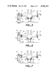
- FIG. 6 An alternative approach to assembling the block 32 between the base step 33 and the fixed guide plate 18 is portrayed in FIG. 6, wherein a compression spring 36 is clamped between a protruding section 38 formed with the base and the guide plate 18.
- FIG. 7 Another implementation of assembling the block 32 between the base 16 and the fixed guide plate 18 is illustrated in FIG. 7, wherein a threaded bolt 40 passes through a clearance hole in the fixed guide plate 18 and a slot in the compensating block 32 to engage a threaded step portion 40 of the base.
- the block 32 is preferably made to be stiff relative to the bolt 40.
- the thermal expansion coefficient of the block 32 is not influenced by the bolt 40 and provides the desired compensation which allows the orientation of the guide plates to be properly maintained so that carriage roll and off-track head operation are virtually eliminated.
Landscapes
- Moving Of Heads (AREA)
Abstract
Description
Claims (11)
Priority Applications (1)
| Application Number | Priority Date | Filing Date | Title |
|---|---|---|---|
| US06/826,689 US4703377A (en) | 1986-02-06 | 1986-02-06 | Thermal compensation for disk drive carriage assembly |
Applications Claiming Priority (1)
| Application Number | Priority Date | Filing Date | Title |
|---|---|---|---|
| US06/826,689 US4703377A (en) | 1986-02-06 | 1986-02-06 | Thermal compensation for disk drive carriage assembly |
Publications (1)
| Publication Number | Publication Date |
|---|---|
| US4703377A true US4703377A (en) | 1987-10-27 |
Family
ID=25247257
Family Applications (1)
| Application Number | Title | Priority Date | Filing Date |
|---|---|---|---|
| US06/826,689 Expired - Lifetime US4703377A (en) | 1986-02-06 | 1986-02-06 | Thermal compensation for disk drive carriage assembly |
Country Status (1)
| Country | Link |
|---|---|
| US (1) | US4703377A (en) |
Cited By (2)
| Publication number | Priority date | Publication date | Assignee | Title |
|---|---|---|---|---|
| US4891724A (en) * | 1988-08-29 | 1990-01-02 | Storage Technology Corporation | Disk drive read/write head rack flexible rail mount apparatus |
| US20100091411A1 (en) * | 2008-10-15 | 2010-04-15 | Fasen Donald J | Non-radial bearing preload |
Citations (5)
| Publication number | Priority date | Publication date | Assignee | Title |
|---|---|---|---|---|
| DE137987C (en) * | ||||
| JPS5211912A (en) * | 1975-07-18 | 1977-01-29 | Hitachi Ltd | Magnetic head position settlement apparatus |
| JPS54163012A (en) * | 1978-06-14 | 1979-12-25 | Mitsubishi Electric Corp | Temperature compensating mechanism |
| DE3202577A1 (en) * | 1981-01-28 | 1982-08-05 | Hitachi, Ltd., Tokyo | MAGNETIC DISK STORAGE WITH MAGNETIC HEAD POSITIONING DEVICE |
| US4549239A (en) * | 1980-11-19 | 1985-10-22 | Ricoh Company, Ltd. | Head carriage for use in a magnetic recording machine |
-
1986
- 1986-02-06 US US06/826,689 patent/US4703377A/en not_active Expired - Lifetime
Patent Citations (5)
| Publication number | Priority date | Publication date | Assignee | Title |
|---|---|---|---|---|
| DE137987C (en) * | ||||
| JPS5211912A (en) * | 1975-07-18 | 1977-01-29 | Hitachi Ltd | Magnetic head position settlement apparatus |
| JPS54163012A (en) * | 1978-06-14 | 1979-12-25 | Mitsubishi Electric Corp | Temperature compensating mechanism |
| US4549239A (en) * | 1980-11-19 | 1985-10-22 | Ricoh Company, Ltd. | Head carriage for use in a magnetic recording machine |
| DE3202577A1 (en) * | 1981-01-28 | 1982-08-05 | Hitachi, Ltd., Tokyo | MAGNETIC DISK STORAGE WITH MAGNETIC HEAD POSITIONING DEVICE |
Cited By (3)
| Publication number | Priority date | Publication date | Assignee | Title |
|---|---|---|---|---|
| US4891724A (en) * | 1988-08-29 | 1990-01-02 | Storage Technology Corporation | Disk drive read/write head rack flexible rail mount apparatus |
| US20100091411A1 (en) * | 2008-10-15 | 2010-04-15 | Fasen Donald J | Non-radial bearing preload |
| US8284522B2 (en) * | 2008-10-15 | 2012-10-09 | Hewlett-Packard Development Company, L.P. | Non-radial bearing preload |
Similar Documents
| Publication | Publication Date | Title |
|---|---|---|
| US5191492A (en) | Mechanisms for a closed loop head positioner for streaming tape drives | |
| US5189578A (en) | Disk system with sub-actuators for fine head displacement | |
| CA1311838C (en) | Magnetic head air bearing slider | |
| US6005743A (en) | Disk drive with multiple actuators on a single axis and disk surfaces of differing track pitch | |
| US5063464A (en) | Low profile suspension | |
| US5790347A (en) | Head suspension load beam and flexure construction for reducing structural height | |
| US5097368A (en) | Information recording apparatus with a non-Newtonian liquid bearing | |
| US5142424A (en) | Floatable information-reading head support configured to prevent forward pitch | |
| US4860135A (en) | Thermal compensation mechanism for magnetic disk drive data storage units | |
| IE970591A1 (en) | A slider and method for making same | |
| HK1008157B (en) | Information recording apparatus with a non-newtonian liquid forbearing the transducer | |
| US6950281B2 (en) | Negative pressure type head slider and disk drive | |
| US4807070A (en) | Supporting structure for dual magnetic head | |
| US4703377A (en) | Thermal compensation for disk drive carriage assembly | |
| US5831793A (en) | Suspension assembly shock absorber | |
| US6163438A (en) | Supporting mechanism of a magnetic head slider employing a lubricant between the surfaces of the slider and portions of the mounting gimbal | |
| US7236330B2 (en) | Disk head stability system | |
| KR20020087101A (en) | Dynamically symmetric actuator | |
| US7573680B1 (en) | Etched laminate structures for reducing track mis-registration in a disk drive suspension | |
| DE69020433T2 (en) | Head mounting structure for high capacity disk drive. | |
| US3579213A (en) | Magnetic head accessing mechanism utilizing spring bias | |
| US5838518A (en) | Disk drive suspension for increasing the arm to disk clearance | |
| US5629820A (en) | Structure for supporting head suspension of actuator of magnetic disk drive | |
| JPS63255877A (en) | Disc driver having heat compensation means for carriage assembly | |
| US6421207B1 (en) | Contact type magnetic disk drive |
Legal Events
| Date | Code | Title | Description |
|---|---|---|---|
| AS | Assignment |
Owner name: PRIAM CORPORATION, 20 W. MONTAGUE EXPRESSWAY, SAN Free format text: ASSIGNMENT OF ASSIGNORS INTEREST.;ASSIGNOR:HAZEBROUCK, HENRY B.;REEL/FRAME:004552/0695 Effective date: 19860130 Owner name: PRIAM CORPORATION, CALIFORNIA Free format text: ASSIGNMENT OF ASSIGNORS INTEREST;ASSIGNOR:HAZEBROUCK, HENRY B.;REEL/FRAME:004552/0695 Effective date: 19860130 |
|
| AS | Assignment |
Owner name: PRIAM (DELAWARE) CORPORATION, SAN JOSE, CALIFORNIA Free format text: ASSIGNMENT OF ASSIGNORS INTEREST.;ASSIGNOR:PRIAM CORPORATION, A CA. CORP.;REEL/FRAME:004701/0131 Effective date: 19870413 Owner name: PRIAM (DELAWARE) CORPORATION, A DE. CORP.,CALIFOR Free format text: ASSIGNMENT OF ASSIGNORS INTEREST;ASSIGNOR:PRIAM CORPORATION, A CA. CORP.;REEL/FRAME:004701/0131 Effective date: 19870413 |
|
| STCF | Information on status: patent grant |
Free format text: PATENTED CASE |
|
| AS | Assignment |
Owner name: ORCA TECHNOLOGY CORPORATION, A CA CORP. Free format text: ASSIGNMENT OF ASSIGNORS INTEREST.;ASSIGNOR:PRIAM CORPORATION;REEL/FRAME:005397/0970 Effective date: 19900601 Owner name: SEQUEL, INC., A CA CORP. Free format text: ASSIGNMENT OF ASSIGNORS INTEREST.;ASSIGNOR:PRIAM CORPORATION;REEL/FRAME:005397/0970 Effective date: 19900601 |
|
| FEPP | Fee payment procedure |
Free format text: PAYOR NUMBER ASSIGNED (ORIGINAL EVENT CODE: ASPN); ENTITY STATUS OF PATENT OWNER: LARGE ENTITY |
|
| FPAY | Fee payment |
Year of fee payment: 4 |
|
| FEPP | Fee payment procedure |
Free format text: PAYER NUMBER DE-ASSIGNED (ORIGINAL EVENT CODE: RMPN); ENTITY STATUS OF PATENT OWNER: LARGE ENTITY |
|
| REMI | Maintenance fee reminder mailed | ||
| AS | Assignment |
Owner name: SAMSUNG ELECTRONICS CO., LTD., KOREA, REPUBLIC OF Free format text: ASSIGNMENT OF ASSIGNORS INTEREST;ASSIGNOR:ROBERTSON, JEROME E., AS TRUSTEE FOR ORCA TECHNOLOGY CORPORATION;REEL/FRAME:007603/0395 Effective date: 19950530 |
|
| FPAY | Fee payment |
Year of fee payment: 8 |
|
| SULP | Surcharge for late payment | ||
| FPAY | Fee payment |
Year of fee payment: 12 |