US470166A - Can-labeling machine - Google Patents
Can-labeling machine Download PDFInfo
- Publication number
- US470166A US470166A US470166DA US470166A US 470166 A US470166 A US 470166A US 470166D A US470166D A US 470166DA US 470166 A US470166 A US 470166A
- Authority
- US
- United States
- Prior art keywords
- label
- paste
- runway
- bed
- belt
- Prior art date
- Legal status (The legal status is an assumption and is not a legal conclusion. Google has not performed a legal analysis and makes no representation as to the accuracy of the status listed.)
- Expired - Lifetime
Links
- 238000002372 labelling Methods 0.000 title description 8
- 238000005096 rolling process Methods 0.000 description 13
- 230000006872 improvement Effects 0.000 description 7
- 230000000994 depressogenic effect Effects 0.000 description 5
- 230000037303 wrinkles Effects 0.000 description 3
- 230000001174 ascending effect Effects 0.000 description 2
- 238000010276 construction Methods 0.000 description 2
- 230000000694 effects Effects 0.000 description 1
- 230000005484 gravity Effects 0.000 description 1
Images

Classifications
-
- B—PERFORMING OPERATIONS; TRANSPORTING
- B65—CONVEYING; PACKING; STORING; HANDLING THIN OR FILAMENTARY MATERIAL
- B65C—LABELLING OR TAGGING MACHINES, APPARATUS, OR PROCESSES
- B65C3/00—Labelling other than flat surfaces
- B65C3/06—Affixing labels to short rigid containers
- B65C3/08—Affixing labels to short rigid containers to container bodies
- B65C3/10—Affixing labels to short rigid containers to container bodies the container being positioned for labelling with its centre-line horizontal
- B65C3/12—Affixing labels to short rigid containers to container bodies the container being positioned for labelling with its centre-line horizontal by rolling the labels onto cylindrical containers, e.g. bottles
Definitions
- This invention relates to improvements in can-labeling machines, having for its object principally to lay and wrap the label smoothly upon the body of the can and to join and fix the lapped ends of the label automatically while the can travels by gravity with a rolling motion through the label feeding and pasting devices.
- the machines to which these improvements pertain have an inclined runway, and the cans being laid on at the higher end are released at intervals of time to roll down the machine and through the several devices situated at different points in the length of the incline, by which the body of the can is coated with paste, the label is presented in the path of the can to be taken up and wrapped by the 2 5 rolling contact of the can, and the lapped ends of the label are pasted and joined together.
- One part or feature of the present improve ments has for its object to prevent the label from. buckling or forming wrinkles while being wrapped on the can; and it consists in a novel construction of track or guide-rails having peculiar depressions and elevations in combination with the label-bed, by which vari-. able movements of the can in a vertical direc- 3 5 tion with respectto the label on the label-bed in the bottom of the runway are produced during 'the rolling motion or travel of the can over the label, the effect of which is to draw the label smoothly upon the can-body and 40 cause it to adhere without buckle or wrinkle.
- auxiliary pasting device for fixing the ends of the labels, and the same consists in certain construction and combination of paste-trough, traveling paste-belt arranged to apply a narrow strip or line of paste upon the inner face of the upper or outside lap just before that end of the label is taken up from the label-bed by the can, and a beltfeeding or moving mechanism, through the the label.
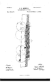
- Figure l of the drawings represents in side elevation and generally in longitudinal section the inclined runway and parts of a labeling-machine containing my improvements.
- Fig. 2 is a plan or top view of the same.
- Fig. 3 is a vertical cross-section through the lappasting device, the same being a section taken at about the line m 00, Fig. 1, on the lefthand side of the line.
- Fig. 4 is a cross-section at the line a 1 Fig. 1, on an enlarged scale, and on the left-hand side of that line.
- Fig. 5 is a detail View, in perspective, of the presser-plate that acts upon the lap-pasting belt from above.
- Fig. 6 is a detail View of one of the fingers or stops that hold down
- Fig. 7 is a longitudinal section on an enlarged scale through the runway and label-bed, showing the elevated and depressed track for the cans.
- A indicates the inclined runway, in which the cans descend with a rolling motion and at suitable degree of inclination to acquire the momentum necessary to carry them through the several operating parts of the machine.
- B B are pivoted stops that control the cans at the head or upper end of the runway and regulate the headway or interval between one can and the next. These stops are not claimed herein, as I have made them the subject-matter of a separate application for Letters Pato ent, filed May 27, 1891, Serial N 0. 394,244.
- C is a paste-roller set over the runway beneath a paste-fountain D, and in position to run in contact with and apply acoat of paste to the surface of the can passing in contact 5 with it.
- E is a vertically-movinglabel-bed set in an opening A in the bottom of the runway, and E is a box or compartment of corresponding size, of which the bed E forms the movable bot- I00 tom.
- Cords and weights E E support the weight of the bed and the pile of labels on it, and feed the topmost label of the pile to the level of the bottom of the runway.
- the labels are held down in that position by yielding stopsF F,settingfro1n opposite sidesof therunwayover the edges of the topmost label, and the stops are thrown back by curved fingers F F acted on by the can itself, and held out of action also until that portion of the label between the first or leading end and the point where the stops set over it has become attached to the can and is raised above the line of stops.
- the track for the cans is elevated above the level of the bed and is composed of abruptlyinclined portions R R R and horizontal or level portions R, that act upon the can for the remainder of its run over the label to give it movement in a Vertical direction, at first abruptly as the can leaves the depressed part of the track and runs up the incline and then with a more gradual elevation, but still increasing in Vertical height, and afterward on a level run substantially parallel with the label-bed, but above it and also above the lap-pasting device.
- variable movements in the rolling motion of the can have the efiect to produce a certain amount of tension or pulling force on the label, and thereby prevent the tendency to buckle or wrinkle that is found to take place when the can has a simple rolling contact upon the fiat label, and as thus arranged for operation the depressed and elevated portions of the track for the cans insure smooth and uniform wrapping of the label under a quite rapid motion of the can down the runway.
- a line of paste is applied along the edge of its upper face by a separate pasting device consisting of the endless paste-carrying belt G, the paste-trough G, and a yielding presserplate H, setting directly over the paste-belt and in the path of the can.
- the presser H is a flat plate attached to the outer ends of spring-arms II II, that are fixed on the outside of the label-box by the opposite ends, and the plate plays at the ends in slots (not shown) in the standing sides of the runway.
- the lower edge of the plate is bent down perpendicularly or has an apron-piece H fixed to that edge to set in a guide-slot a in the bottom of the runway.
- the presser-plate has a yielding movement in a perpendicular direction and is pressed down by the weight of the can against the paste-carrier beneath it.
- a line of paste is therefore applied across the end of the lable as often as a can rolls over the plate.
- the springs act to raise the plate so that the pastebelt may rise clear of the lable under it as soon as the can has passed over, and the top surface of the plate stands just below the level of the track on which the can runs so that a short drop or abrupt descent of the cans upon the plate is produced.
- the plate therefore is set down against thelable with aquick movement of shorter duration than if it were pressed down by the rolling movement alone, and the end of the lable while receiving its propercoat of paste for the lap is quickly raised that it may be drawn out frombeneath the paste-belt as the can leaves the lower edge of the presser-plate.
- the inner face of the lap is thus coated with paste before being pressed against the first-laid end of the lable on the can.
- presser-roller L is mounted in yielding-arms J over the runway with a spring 7a to hold the roller against the can with sufficient pressure to produce rolling contact.
- the paste-belt is moved through the trough by a pawl, lever, and ratchet-wheel applied to one of the belt-carrying pulleys through the medium of the pivoted inclines H M, the rocking lever N, and connecting-rod P.
- the ratchet-wheel m is fixed on the shaft 9 outside the trough, and the pawl-lever N carrying the pawl L is loose on the shaft.
- the rod P attached to the outer end, operates in a downward direction, and a spring is applied to raise the lever.
- the pivoted inclines work in slots in the runway and have suitable projection above the bottom of the runway to give the required movement to the rock-shaft. The weight of the can is thus utilized to move the paste-belt in the intervals when it is out of contact with the lable, so that fresh supply of paste is continually being taken up in the belt.
- the combination with the inclined runway, of the labelfeeding bed, the yielding fingers, and the tracks for the can, having a depressed portion below the top level of the labels and an ascending incline and elevated portion along the side of the label-bed, arranged for operation as described.
- an auxiliary lap-pasting device to paste the upper face of the label, being Wrapped before the end of the label is fixed on the can, consisting of the endless paste-carrying belt having movement through a paste-trough and across the end of the label, the yielding presser-plate over said belt in the path of the rolling cans, and mechanism actuated by the momentum of the rolling can and connected with the paste-carrying belt to move the same step by step through the paste-trough, substantially as described, for the purposes set forth.
Landscapes
- Labeling Devices (AREA)
Description
(No Model.) 2 Sheets-Sheet 1. V G. E. NEWELL. CAN LABELING MACHINE.
No. 470,166. Patented Mar. 1, 1892.
TH! NOMII NYE" $9., FHQTQ'LIYHO, WAIHENGTON, D. C.
(No Model.) 0. E. NEWE LL.
(JAN LABELING MACHINE.
2 Sheets-Sheet 2.
Patented Mar. 1,1892.
IF I Wifn ESSEE UNITED "STATES PATENT OFFICE.
CHARLES E. NEWVELL, OF SAN FRANCISCO, CALIFORNIA, ASSIGNOR TO THE PACIFIC LABELING COMPANY, OF CALIFORNIA.
CAN-LABELING MACHINE.
SPECIFICATION forming part of Letters Patent No. 470,166, dated March 1, 1892. Application filed June 6, 1891. Serial No. 395,327. (No model.)
To all whom it may concern.-
Be it known that 1, CHARLES E. NEWELL, a citizen of the United States, residing in the city and county of San Francisco, State of California, have invented certain new and useful Improvements in Can-Labeling Machines, of which the following is a specification.
This invention relates to improvements in can-labeling machines, having for its object principally to lay and wrap the label smoothly upon the body of the can and to join and fix the lapped ends of the label automatically while the can travels by gravity with a rolling motion through the label feeding and pasting devices.
The machines to which these improvements pertain have an inclined runway, and the cans being laid on at the higher end are released at intervals of time to roll down the machine and through the several devices situated at different points in the length of the incline, by which the body of the can is coated with paste, the label is presented in the path of the can to be taken up and wrapped by the 2 5 rolling contact of the can, and the lapped ends of the label are pasted and joined together.
One part or feature of the present improve ments has for its object to prevent the label from. buckling or forming wrinkles while being wrapped on the can; and it consists in a novel construction of track or guide-rails having peculiar depressions and elevations in combination with the label-bed, by which vari-. able movements of the can in a vertical direc- 3 5 tion with respectto the label on the label-bed in the bottom of the runway are produced during 'the rolling motion or travel of the can over the label, the effect of which is to draw the label smoothly upon the can-body and 40 cause it to adhere without buckle or wrinkle.
Another part or feature of these improvements relates to an auxiliary pasting device for fixing the ends of the labels, and the same consists in certain construction and combination of paste-trough, traveling paste-belt arranged to apply a narrow strip or line of paste upon the inner face of the upper or outside lap just before that end of the label is taken up from the label-bed by the can, and a beltfeeding or moving mechanism, through the the label.
medium of which the rolling can is caused to move the paste-belt through the trough and across the label at intervals.
These parts and improvements I have constructed and arranged for operation with other 5 5 parts to form an improved machine or apparatus for applying labels to fruit-cans, substantially as hereinafter described, and as illustrated in the accompanying drawings, which form part of this specification.
Figure l of the drawings represents in side elevation and generally in longitudinal section the inclined runway and parts of a labeling-machine containing my improvements. Fig. 2 is a plan or top view of the same. Fig. 3 is a vertical cross-section through the lappasting device, the same being a section taken at about the line m 00, Fig. 1, on the lefthand side of the line. Fig. 4 is a cross-section at the line a 1 Fig. 1, on an enlarged scale, and on the left-hand side of that line. Fig. 5 is a detail View, in perspective, of the presser-plate that acts upon the lap-pasting belt from above. Fig. 6 is a detail View of one of the fingers or stops that hold down Fig. 7 is a longitudinal section on an enlarged scale through the runway and label-bed, showing the elevated and depressed track for the cans.
A indicates the inclined runway, in which the cans descend with a rolling motion and at suitable degree of inclination to acquire the momentum necessary to carry them through the several operating parts of the machine.
B B are pivoted stops that control the cans at the head or upper end of the runway and regulate the headway or interval between one can and the next. These stops are not claimed herein, as I have made them the subject-matter of a separate application for Letters Pato ent, filed May 27, 1891, Serial N 0. 394,244.
C is a paste-roller set over the runway beneath a paste-fountain D, and in position to run in contact with and apply acoat of paste to the surface of the can passing in contact 5 with it.
E is a vertically-movinglabel-bed set in an opening A in the bottom of the runway, and E is a box or compartment of corresponding size, of which the bed E forms the movable bot- I00 tom. Cords and weights E E support the weight of the bed and the pile of labels on it, and feed the topmost label of the pile to the level of the bottom of the runway. The labels are held down in that position by yielding stopsF F,settingfro1n opposite sidesof therunwayover the edges of the topmost label, and the stops are thrown back by curved fingers F F acted on by the can itself, and held out of action also until that portion of the label between the first or leading end and the point where the stops set over it has become attached to the can and is raised above the line of stops. The general form and position of these fingers are shown in Figs. 2 and 6. They swing on the pivots f and are thrown forward into position by fiat springs F acting against the back. The curvature of their front or inner edges is such that the rolling can by contact produces a regular movement backward and a gradual or even return of the stops without abrupt movement, so that the stops are prevented from catching above or against the edges of the label and are caused to set into place over the next label and hold it down without fail. At this point in the runway where the label is taken up from under the stops and the operation of wrapping it around the can begins I cause the weight of the can to depress the pile of labels at or in the vicinity of the stops sufficiently to keep the uppermost label slightly below the line of stops until the can has released them, and for such purpose I depress or sink the track for the can on each side of the runway just below the level of the pile of labels, as from s to if, so that the full weight of the filled can is brought to bear upon the pile of labels while the can runs on such depressed portion of the track.
From that portion of the label-bed beyond stops and onward to the lap-pasting device the track for the cans is elevated above the level of the bed and is composed of abruptlyinclined portions R R R and horizontal or level portions R, that act upon the can for the remainder of its run over the label to give it movement in a Vertical direction, at first abruptly as the can leaves the depressed part of the track and runs up the incline and then with a more gradual elevation, but still increasing in Vertical height, and afterward on a level run substantially parallel with the label-bed, but above it and also above the lap-pasting device. These variable movements in the rolling motion of the can have the efiect to produce a certain amount of tension or pulling force on the label, and thereby prevent the tendency to buckle or wrinkle that is found to take place when the can has a simple rolling contact upon the fiat label, and as thus arranged for operation the depressed and elevated portions of the track for the cans insure smooth and uniform wrapping of the label under a quite rapid motion of the can down the runway. Before the end of the label is drawn away from the bed a line of paste is applied along the edge of its upper face by a separate pasting device consisting of the endless paste-carrying belt G, the paste-trough G, and a yielding presserplate H, setting directly over the paste-belt and in the path of the can. The belt is carried through the trough by guide-pulleys or rollers The presser H is a flat plate attached to the outer ends of spring-arms II II, that are fixed on the outside of the label-box by the opposite ends, and the plate plays at the ends in slots (not shown) in the standing sides of the runway. The lower edge of the plate is bent down perpendicularly or has an apron-piece H fixed to that edge to set in a guide-slot a in the bottom of the runway. As thus arranged, the presser-plate has a yielding movement in a perpendicular direction and is pressed down by the weight of the can against the paste-carrier beneath it. A line of paste is therefore applied across the end of the lable as often as a can rolls over the plate. The springs act to raise the plate so that the pastebelt may rise clear of the lable under it as soon as the can has passed over, and the top surface of the plate stands just below the level of the track on which the can runs so that a short drop or abrupt descent of the cans upon the plate is produced. The plate therefore is set down against thelable with aquick movement of shorter duration than if it were pressed down by the rolling movement alone, and the end of the lable while receiving its propercoat of paste for the lap is quickly raised that it may be drawn out frombeneath the paste-belt as the can leaves the lower edge of the presser-plate. The inner face of the lap is thus coated with paste before being pressed against the first-laid end of the lable on the can.
To unite the edges and finish the lap, presser-roller L is mounted in yielding-arms J over the runway with a spring 7a to hold the roller against the can with sufficient pressure to produce rolling contact.
The paste-belt is moved through the trough by a pawl, lever, and ratchet-wheel applied to one of the belt-carrying pulleys through the medium of the pivoted inclines H M, the rocking lever N, and connecting-rod P. The ratchet-wheel m is fixed on the shaft 9 outside the trough, and the pawl-lever N carrying the pawl L is loose on the shaft. The rod P, attached to the outer end, operates in a downward direction, and a spring is applied to raise the lever. The pivoted inclines work in slots in the runway and have suitable projection above the bottom of the runway to give the required movement to the rock-shaft. The weight of the can is thus utilized to move the paste-belt in the intervals when it is out of contact with the lable, so that fresh supply of paste is continually being taken up in the belt.
Having thus fully described my invention, what I claim, and desire to secure by Letters Patent, is-
1. In a can-labeling machine, the combination, with the inclined runway and label-feeding bed, of the track or guide railsat the sides of the label-bed, having ascending inclines and elevated portions, as described, above the level of the labels, by which variable movements in avertical direction are imparted to the can in its run over the label, as and for the purpose set forth.
2. In a can-labeling machine, the combination, with the inclined runway, of the labelfeeding bed, the yielding fingers, and the tracks for the can, having a depressed portion below the top level of the labels and an ascending incline and elevated portion along the side of the label-bed, arranged for operation as described.
3. In a can-labeling machine, the combination,with the inclined runway and label-feeding bed, of a lap-pasting device arranged across the lower end of the label and adapted to apply a coat of paste to the upper face of the label before it is drawn away by the can,
consisting of a paste-carrying belt having movement through a trough to take up a supply of paste, and a yielding presser-plate located over the paste-belt in the path of the rolling can and adapted to bring the belt into contact with the label beneath it by the weight of the can, substantially as described.
4. In a can-labeling machine, an auxiliary lap-pasting device to paste the upper face of the label, being Wrapped before the end of the label is fixed on the can, consisting of the endless paste-carrying belt having movement through a paste-trough and across the end of the label, the yielding presser-plate over said belt in the path of the rolling cans, and mechanism actuated by the momentum of the rolling can and connected with the paste-carrying belt to move the same step by step through the paste-trough, substantially as described, for the purposes set forth.
In testimony that I claim the foregoing I have hereunto set my hand and seal.
CHAS. E. NEWELL. [1,. s.] Witnesses: I
WM. MAGEE, EDWARD E. OSBORN.
Publications (1)
| Publication Number | Publication Date |
|---|---|
| US470166A true US470166A (en) | 1892-03-01 |
Family
ID=2539026
Family Applications (1)
| Application Number | Title | Priority Date | Filing Date |
|---|---|---|---|
| US470166D Expired - Lifetime US470166A (en) | Can-labeling machine |
Country Status (1)
| Country | Link |
|---|---|
| US (1) | US470166A (en) |
-
0
- US US470166D patent/US470166A/en not_active Expired - Lifetime
Similar Documents
| Publication | Publication Date | Title |
|---|---|---|
| US1346356A (en) | Automatic reel-threading device | |
| US1117260A (en) | Bread-wrapping machine. | |
| US3831784A (en) | Carton magazine and means for loading the same | |
| US470165A (en) | Can-labeling machine | |
| US716434A (en) | Labeling-machine. | |
| US656789A (en) | Labeling-machine. | |
| US558064A (en) | Fornia | |
| US753661A (en) | Machine for wrapping packages. | |
| US488791A (en) | And lucy | |
| US497368A (en) | Can-labeling machine | |
| US1144772A (en) | Feeding device for packet-making machines. | |
| US754460A (en) | Labeling-machine. | |
| US612825A (en) | Can-labeling machine | |
| US436390A (en) | Apparatus foe | |
| US529257A (en) | Can-labeling machine | |
| US203200A (en) | Improvement in can-labeling machines | |
| US1108876A (en) | Delivery mechanism for labeling-machines. | |
| US482542A (en) | butler | |
| US589673A (en) | Machine | |
| US942715A (en) | Machinery or apparatus for forming or making paper bags. | |
| US550212A (en) | Machine for manufacturing pencils | |
| US1041543A (en) | Labeling-machine. | |
| US1072262A (en) | Envelop-sealing machine. | |
| US761080A (en) | Labeling-machine. | |
| US408580A (en) | chambers |