US4697496A - Method and apparatus for handling beltless ammunition in a twin-barreled gun - Google Patents
Method and apparatus for handling beltless ammunition in a twin-barreled gun Download PDFInfo
- Publication number
- US4697496A US4697496A US06/745,135 US74513585A US4697496A US 4697496 A US4697496 A US 4697496A US 74513585 A US74513585 A US 74513585A US 4697496 A US4697496 A US 4697496A
- Authority
- US
- United States
- Prior art keywords
- ammunition
- breech
- oscillating
- chamber
- chute
- Prior art date
- Legal status (The legal status is an assumption and is not a legal conclusion. Google has not performed a legal analysis and makes no representation as to the accuracy of the status listed.)
- Expired - Fee Related
Links
Images


Classifications
-
- F—MECHANICAL ENGINEERING; LIGHTING; HEATING; WEAPONS; BLASTING
- F41—WEAPONS
- F41A—FUNCTIONAL FEATURES OR DETAILS COMMON TO BOTH SMALLARMS AND ORDNANCE, e.g. CANNONS; MOUNTINGS FOR SMALLARMS OR ORDNANCE
- F41A9/00—Feeding or loading of ammunition; Magazines; Guiding means for the extracting of cartridges
- F41A9/35—Feeding multibarrel guns
Definitions
- the invention relates to the handling of beltless ammunition in an automatic weapon system, and in particular to the use of an oscillating breech for loading beltless ammunition into a twin-barreled gun.
- Rapid-fire guns and cannons using multiple barrels are well known to the art and have been devised to fire both belted as well as beltless ammunition.
- the amount of ammunition which such guns can fire is extremely high and the limiting factor of operation often limited by the rate at which such weapons systems can fire or load the unfired rounds, and in the situation of cased ammunition, additionally handle empty cases from fired rounds.
- Marquardt "Rapid-Fire Gun with Two Barrels and a Plurality of Firing Chambers Gun with Two Barrels and a Plurality of Firing Chambers" U.S. Pat. No. 2,972,286.
- application ammunition was provided to the firing mechanism from an upper and lower chute, moving the rounds in opposite directions as best illustrated in Marquardt's FIGS.
- Wiese "Feeding Mechanism in an Automatic Cannon for Firing Caseless Ammunition", U.S. Pat. No. 3,608,424, wherein a four-chambered drum is oscillated by a reversible electric motor.
- Wiese illustrates a single-barreled automatic weapon system which is able to draw ammunition from two independent magazines.
- caseless ammunition is not a practical alternative in all applications and Wiese naturally fails to show any means for removing cartridges since Wiese's automatic weapon system is restricted for use with caseless ammunition.
- the breech is then rotated about an axis perpendicular to the longitudinal axis of the bore to rotate the bore through 90° to align the unfired cartridge with the barrel bore.
- the breech is again rotated about the axis perpendicular to the longitudinal axis of the bore by an additional 90° to align the bore with an ejection opening and with an unfired round from the magazine.
- the new incoming unfired round thereby forces the spent cartridge from the bore out the ejection opening.
- the breech then oscillates back and forth between the firing and the loading/ejection position.
- the system of Ketterer is a single-barreled system and is not adapted to feeding multiple barrels using the same loading system, and therefore includes an inherent limitation in the firing rate of the gun.
- the invention is an automatic gun including a double-barrel wherein each barrel includes a bore having a longitudinal axis for alternately firing beltless cased ammunition from each barrel.
- the gun comprises an oscillating breech or flipper having two breech chambers defined therein.
- the oscillating breech has a longitudinal axis generally parallel to the longitudinal axis of the double barrels.
- the oscillating breech rotates in an oscillating cycle about the longitudinal axis of the breech to alternately position each one of the two breeched chambers defined in the oscillating breech in alignment with a corresponding barrel bore defined in a respective one of the double barrels.
- the breech chambers defined in the oscillating breech are opened at each opposing end of each chamber to permit the ammunition to be slidingly disposed therethrough.
- a mechanism is coupled to the breech for rotating the breech in the oscillating cycle about its longitudinal axis.
- a first ammunition chute is also provided and generally disposed transversely with respect to the longitudinal axis of the oscillating breech.
- a second ammunition chute is transversely disposed with respect to the longitudinal axis of the breech and is disposed on the opposite side of the oscillating breech from the first ammunition chute.
- the first and second ammunition chutes are disposed on opposing sides of the oscillating breech and generally aligned in the same plane.
- the double barrels are disposed below the plane of the first and second ammunition chutes.
- the oscillating breech alternately rotates each chamber of the breech in alignment with the first and second ammunition chutes and subsequently in alignment with a corresponding one of the barrel bores.
- a mechanism for end loading each breech chamber when the breech chamber is rotated in upward position in alignment with the first and second ammunition chutes is also included.
- the loading mechanism includes a cocked rammer which is arranged and configured to force the ammunition from the first and second ammunition chutes into the oscillating breech.
- the ammunition is loaded into each of the breech chambers from either the first or second ammunition chutes thereby forcing ammunition which had previously been loaded in the corresponding breech chamber and fired, or possibly not fired due to malfunction, from the breech chamber into the opposing ammunition chute.
- a buffer mechanism opposing the loader mechanism provided on each ammunition chute buffers the shock of ejection of the ammunition by the loading mechanism from the breech chambers into the opposing ammunition chute.
- the method of the present invention is a method for feeding beltless ammunition cartridges into an automatic gun which includes double barrels wherein each barrel has a barrel bore defined therein and is characterized by a longitudinal axis of the barrel bore.
- the method comprises the steps of delivering the beltless ammunition cartridges at a load position in a first and second ammunition chute.
- the ammunition chutes are generally disposed transversely with respect to the longitudinal axis of the barrel bores of the double barrels.
- the ammunition cartridge delivered to the load position within a corresponding ammunition chute is then forced into the breech chamber which is defined in an oscillating breech disposed between the first and second ammunition chutes.
- the oscillating breech chamber has a longitudinal axis which is generally parallel to the longitudinal axis of the double barrels and rotates in an oscillating cycle about the longitudinal axis of the breech to alternately position each one of the two breech chambers in alignment with a corresponding load position in the ammunition chutes.
- the method continues by forcing a spent ammunition cartridge from each of the corresponding breech chambers into the opposite ammunition chute when the unfired ammunition cartridge is forced into the corresponding breech chamber during the proceeding step of loading.
- beltless ammunition cartridges may be delivered to an automatic gun having double barrels with a quick and smooth action.
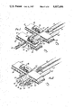
- FIG. 1 is a partial perspective view of the invention.
- FIG. 2 is a partial perspective and elevational view taken through line 2--2 of FIG. 1.
- FIG. 3 is a diagrammatic side view of the loading mechanism shown in FIGS. 1 and 2.
- FIG. 4 is a plan elevational view taken through line 4--4 of FIG. 3.
- FIG. 5 is a timing diagram, illustrating the operation of the gun of FIGS. 1-4.
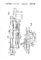
- FIG. 6 is a diagrammatic side view of a second embodiment of the ammunition handling system.
- FIG. 7 is a side elevational and partly cutaway view of the gun diagrammatically depicted in FIG. 6.
- FIG. 8 is a cross-sectional view taken through line 8--8 of FIG. 7.
- the invention is an automated weapons system and in particular an ammunition feeding system in an automatic gun for feeding beltless cartridges to multiple-barreled gun.
- two twin barrels are laid side-by-side and are provided with ammunition by an oscillating breech or flipper.
- "breech" or hereinafter flipper will be taken to mean the oscillating member which aligns the round with the barrel bore regardless of whether or not another member then inserts the round into or seals the end of the bore during firing.
- the oscillating flipper both delivers unfired rounds to the barrels and returns the spent cartridge to two corresponding ammunition chutes.
- the ammunition chutes are disposed above and transversely to the longitudinal axis of the twin barrels. Each chute carries both unfired rounds and spent cartridges.
- a first chute is provided behind the oscillating flipper to provide unfired rounds to a first chamber in the flipper.
- the unfired round is provided from the first chute to the first flipper chamber when the flipper chamber is oscillated upwardly in alignment with the first ammunition chute.
- the flipper then oscillates downwardly to a position of alignment with a first gun barrel and breech mechanism.
- the unfired round is then loaded into the breech and fired by conventional means leaving, or returning as may be the appropriate case, the spent cartridge to the first chamber within the flipper.
- the flipper then oscillates upwardly until the first flipper chamber is again aligned with the first ammunition chute. At this time, the first flipper chamber is also aligned with the second ammunition chute which lies in front of the flipper.
- the spent cartridge is then forced from the first chamber in the flipper into the second ammunition chute.
- the spent cartridge is then moved down the second ammunition chute and disposed of.
- the second flipper chamber is symmetrically disposed about the longitudinal axis of the flipper and operates in conjunction with the first and second ammunition chutes and second barrel in an analogous manner to that described in connection with the first and second ammunition chutes, first flipper chamber and first barrel.
- unfired rounds are delivered through the second ammunition chute, loaded into the second flipper chamber, fired in the second barrel and then the spent cartridges are delivered to the first ammunition chute and disposed of.
- FIG. 1 is a partial perspective in cutaway view of the material operative elements of the invention.
- the weapon system generally denoted by reference numeral 10, includes a first barrel 12, a second barrel 14, first ammunition chute 16, second ammunition chute 18 and flipper 20.
- unfired rounds 22 move by conventional means through first ammunition chute 16 from left to right until they reach a load position within chute 16.
- unfired rounds will be loaded into flipper 20, fired, and the spent rounds will be returned by flipper 20 to second ammunition chute 18.
- Spent rounds 24 then move from right to left in second ammunition chute 18 as illustrated in FIG. 1.
- a belted cartridge driver 26 is disposed on the top of second chute 18 and frictionally contacts the upper sides of spent cartridges 24 by means of a gas driven or electrical driven frictional belt 28 which is run in a direction so as to impart an injection force to spent cartridges 24 to move cartridges 24 from the right to the left as illustrated in FIG. 1.
- a similar cartridge driver (not shown) is provided upstream of flipper 20 in each chute 16 and 18 to urge rounds 22 toward the load position within each chute.
- Unfired rounds 22 and spent cartridges 24 are forced into flipper 20 from first ammunition chute 16 and through flipper 20 into second ammunition chute 18, respectively, by means of a rammer 30, described in greater detail below, which includes a ramming rod 32 which applies an axially aligned end force to unfired rounds 22 and spent cartridges 24 to physically force rounds 22 into and cartridges 24 from flipper 20.
- a shock absorbing buffer is aligned along the axis of the load position in first and second ammunition chutes 16 and 18 to absorb the force of axial impact of spent cartridges 24 as they are forcefully rammed by rammer 30 from flipper 20 into second ammunition chute 18.
- unfired rounds 22 move from the right to the left in second ammunition chute 18 and are forced into a second flipper chamber 36 shown in dotted outline in FIG. 1, the first flipper chamber being concealed out of view in FIG. 1.
- a similar rammer 38 forces unfired rounds 22 into second flipper chamber 36 which is aligned with first and second ammunition chutes 16 and 18 in the view of FIG. 1.
- Flipper 20 rotates downwardly to second barrel 14 and the round is fired.
- the spent cartridge 24 is returned by flipper 20 and axially aligned with first chute 16, whereupon rammer 38 forces spent cartridge 24 into first ammunition chute 16.
- a cartridge buffer 40 is aligned in the load position corresponding to second flipper chamber 36 and absorbs the impact of spent cartridge 24 as it is forced into chute 16.
- a cartridge driver 42 identical to driver 26 described in connection with second ammunition chute 18 is similarly provided on first ammunition chute 16.
- Cartridge driver 42 also includes a belt 44 driven in a direction and in contact with the upper surfaces of spent cartridges 24 in first ammunition chute 16, so that spent cartridges 24 are removed from the load position in first ammunition chute 16. Therefore, unfired rounds 22 and spent cartridges 24 both move right to left in second ammunition chute 18 and from left to right in first ammunition chute 16 in the view of FIG. 1.
- FIG. 2 is a sectional elevational perspective view taken through line 2--2 of FIG. 1. Both first flipper chamber 46 and second flipper chamber 36 are clearly shown and are defined as through-bores running completely through binocular-shaped flipper 20.
- Flipper 20 rotates about a trunion 48 provided at each end of flipper 20, one of which such trunions is shown in FIG. 2.
- Trunion 48 is located on the vertical plane of symmetry of flipper 20 and slightly below the longitudinal axis of flipper 20 to provide an eccentric lift to flipper chambers 36 and 46.
- a cam follower 50 is connected to flipper 20 and extends downwardly to slidingly engage slot 52 defined in cam plate 54.
- flipper 20 is oscillated by means better described in connection with FIGS. 3 and 4 under the control of cam plate 54 from an alignment position with ammunition chute 16 and 18 to an alignment position with breech bores 56 and 58 corresponding to first and second barrels 12 and 14, respectively.
- weapon system 10 is powered by buffered pnuematic cylinder 60 communicating with and powered by discharge gases from barrels 12 and 14.
- Piston 62 within pnuematic cylinder 60 drives a rod 64 connected to cam plate 54.
- Rod 64 reciprocates in a forward and rearward direction within weapon system 10, which is shown as a left-to-right movement in the view of FIG. 3.
- Flange 66 rigidly connects cam plate 54 to reciprocating rod 64.
- cam 54 includes a serpentine slot 52 through which cam follower 50 is disposed.
- Cam follower 50 is slidingly held within a horizontal plane by means of sliding end bearings 68.
- serpentine slot 52 will be driven from one extremity to the other past cam follower 50 thereby causing flipper 20 to rotate about trunion 48.
- a dwell period is provided at the end movement of cam follower within slot 52, during which dwell period cartridges 22 are loaded into flipper 20 as described in greater detail in connection with the timing diagram of FIG. 5.
- Rammers 30 and 38 are also driven by means of coupling with reciprocating rod 64. Extensions 70a and b from rod 64 extends upwardly from rod 64 to each rammer. For example, first rammer 30 is cocked against a spring loaded drive by extension 70a as rod 64 and extension 70a move from the right to the left in the view of FIG. 3. When fully cocked, rammer 30 is locked into position by latch 72a bearing against flange 74a.
- second rammer 38 is moved from the left to the right by extension 70b thereby compressing its corresponding spring load and being latched in position by latch 72b bearing against flange 74b.
- Latches 72a and 72b are triggered by extensions 76a and 76b connected to rod 64, or as diagrammatically shown in FIG. 3, indirectly connected to rod 64 through extensions 70a and 70b, respectively.
- first rammer 30 is being cocked against its spring load by extension 70a
- second rammer 38a which would have previously have been cocked is triggered by contact between extension 76b with latch 72b.
- the released rammer 38 is driven by a spring thereby forcing cartridge 22 against the spent cartridge within the corresponding bore in flipper 20 to effectuate the through-load of the round into flipper 20 as previously described in connection with FIGS. 1 and 2.
- Reciprocating movement of buffered pnuematic cylinder 60 is controlled by a shuttle valve 78.
- Shuttle valve 78 in turn is operated by linkage, generally denoted by reference numeral 80.
- Linkage 80 comprises a stem connected to shuttle valve 78, an arm, toggle levers 79a and b, and tabs.
- Stem 81 is rigidly connected to and integral with longitudinal arm which is free to reciprocate in a direction generally parallel to the reciprocation of rammers 30 and 38.
- Each end of arm is rotatably coupled to a corresponding lever 79a or 79b.
- Each lever 79a and b pivots about a fixed pivot point depicted in FIG. 3 as at the midpoint of each lever 79a or 79b.
- each lever 79a or 75b is disposed to contact a rigid corresponding tab extending from rammer 30 or 38 respectively.
- tab respectively will cause arm 83 to reciprocate by virtue of the motive force coupled thereto through lever 74a or b respectively.
- Shuttle valve 78 is thus operated to control piston 60 in a closed loop pneumatic circuit, since the motive gas is provided to piston 60 through valve 78.
- FIG. 5 illustrates the timing of weapon system 10 illustrated in FIGS. 1-4.
- the horizontal axis represents time in milliseconds.
- Line 82 represents the position of flipper 20 between the up position and down position corresponding, for example, to the up or down position of first flipper chamber 46. Beginning with a down position at time zero, flipper 20, or more specifically chamber 46, moves to the up position within approximately 11 milliseconds. Movement of flipper 20 is caused by the forward movement of pneumatic cylinder 60 in rod 62 as illustrated by line 84 at the top of FIG. 5.
- first rammer 30 whose movement is represented by line 86, triggers at point 88 which causes the rammer to press up against the end of a live round 22 in first chute 16 which is lying in front of rammer 30. That live round cannot enter flipper chamber 46 until chamber 46 is in its full up position at the end of the stroke of piston 60.
- live round 22 is then in line with spent cartridge 24 which is then resting within chamber 46, and rammer 30 then forces round 22 into chamber 46 pushing spent cartridge 24 ahead of it into second ammunition chute 18. Spent cartridge 24 butts up against buffer 34 described in FIG. 1 which stops both spent cartridge 24 and unfired round 22 within chamber 46.
- Buffer 34 stops round 22 with a less than 1000 G axial load. Meanwhile, a live round, which had been inserted in second flipper chamber 36 is fired during interval 90 shown of line 82. Flipper 20 remains in place during a dwell period indicated by line 82 extending from 11 milliseconds to 21 milliseconds after the beginning of the cycle for an interval of 10 milliseconds. However, prior to this time, second rammer 38 has been retracting as shown by line 92 and was latched in the cocked position at point 94. Second rammer 38 has been fully retracted from second ammunition chute 18 by time 94 after which a live round 22 will advance in ammunition chute 18 as illustrated by line 96 in FIG. 5. Advance of round 22 in chute 18 occurs during interval 98. This round is now in position to be loaded when second rammer 38 is triggered at point 100, as shown on line 92.
- first rammer 30 has loaded a new round from first ammunition chute 60 into first flipper chamber 46 during interval 102 of line 86.
- first rammer 30 will trigger shuttle valve 78 which causes pneumatic cylinder 60 to drive in the opposite direction as shown on line 84 beginning at point 104. This assures proper sequencing should the spring-loaded rammer be slowed due to dirt or debris.
- Flipper 20 cannot rotate on a partially rammed cartridge and a jam is therefore avoided.
- Rearward motion of rod 62 rotates flipper 20 downwardly as depicted in interval 106 of line 82 and also causes first rammer 30 to be retracted as shown in interval 108 of line 86.
- second rammer 38 This ultimately triggers second rammer 38 at point 100 just prior to the load cycle during interval 110 shown on line 92.
- flipper 20 dwells in its down position in interval 112 of line 82 and first barrel 12 is fired during interval 114.
- Second rammer 38 inserts an unfired round 22 into second flipper chamber 36 during interval 110 thereby pushing a spent cartridge 24 remaining in first flipper chamber 36 into first ammuntion chute 16 for return.
- shuttle valve 78 is again tripped at point 116 as shown on line 84 by second rammer 38, thereby causing the piston within cylinder 60 to move forward during interval 118 to once again restart the cycle.
- FIG. 6 A diagrammatic side view of a second embodiment of the invention is shown in FIG. 6 wherein the gun of FIGS. 1-5 has been modified to include a booster.
- weapon system 10 is primarily powered by gun gasses.
- aircraft compressed air or electrical power is used to power the gun, especially when a dud is encountered. Should a dud round be encountered, the firing rate of weapon system 10 would momentarily drop from 2500 to 1395 rounds per minute until the dud is replaced and the gun begins firing again at the higher rate.
- a booster cylinder 120 is connected in tandem to pneumtic cylinder 60 previously described. Both cylinders are controlled by separate shuttle valves to prevent mixing of gun gasses and aircraft compressed air.
- cylinder 60 continues to be controlled by shuttle valve 78.
- the pneumatic circuit has been omitted for the sake of clarity and is provided between shuttle valves 78 and cylinder 60 in a conventional manner.
- Booster cylinder 120 is in turn controlled by an independent shuttle valve 122.
- shuttle valves 78 and 122 are both connected and in tandem with the same linkage 80 which is driven by rammers 30 and 38.
- Booster cylinder 120 runs on compressed air from the aircraft or gun vehicle. Buffered cylinders 60 continues to be operated solely by discharge gasses from weapon system 10. In the illustrated embodiment, booster cylinder 120 produces approximately 90% of the power requirement to operate weapon system 10.
- FIG. 7 shows a side elevational assembly view of weapon system 10.
- Rod 62 extends from a cylinder housing 124 which includes both pneumatic cylinder 60 and booster cylinder 120.
- Cam plate 54 in actuality, is not a flat plate as suggested by the simplified drawings of FIGS. 1-6, but is a plate curved to accommodate the rotational movement of cam follower 50 as flipper 20 rotates, the curvature of which is better shown in sectional view in FIG. 8 taken through line 8--8 of FIG. 7.
- FIG. 8 graphically illustrates the alignment of flipper chambers 36 and 46 when flippers 20 reaches the extreme dwell position within cam plate 54 leaving one flipper chamber in alignment with its corresponding ammunition chute, and the other flipper chamber in alignment with its corresponding gun barrel.
- a breech block 126 provides a reference attachment point for each of the elements of the gun. Namely, for ammunition chutes 16 and 18, for pivotal coupling to flipper 20, for sliding attachment through bearings 68 as best shown in the sectional view of FIG. 8 and for the slidable mounting of rammers 30 and 38 as shown with respect to rammer 30, in partial cutaway view in FIG. 7.
Landscapes
- Engineering & Computer Science (AREA)
- General Engineering & Computer Science (AREA)
- Portable Nailing Machines And Staplers (AREA)
Abstract
Description
Claims (16)
Priority Applications (1)
| Application Number | Priority Date | Filing Date | Title |
|---|---|---|---|
| US06/745,135 US4697496A (en) | 1985-06-17 | 1985-06-17 | Method and apparatus for handling beltless ammunition in a twin-barreled gun |
Applications Claiming Priority (1)
| Application Number | Priority Date | Filing Date | Title |
|---|---|---|---|
| US06/745,135 US4697496A (en) | 1985-06-17 | 1985-06-17 | Method and apparatus for handling beltless ammunition in a twin-barreled gun |
Publications (1)
| Publication Number | Publication Date |
|---|---|
| US4697496A true US4697496A (en) | 1987-10-06 |
Family
ID=24995397
Family Applications (1)
| Application Number | Title | Priority Date | Filing Date |
|---|---|---|---|
| US06/745,135 Expired - Fee Related US4697496A (en) | 1985-06-17 | 1985-06-17 | Method and apparatus for handling beltless ammunition in a twin-barreled gun |
Country Status (1)
| Country | Link |
|---|---|
| US (1) | US4697496A (en) |
Cited By (6)
| Publication number | Priority date | Publication date | Assignee | Title |
|---|---|---|---|---|
| US4967642A (en) * | 1989-02-14 | 1990-11-06 | Ion Mihaita | Machine gun |
| US5353678A (en) * | 1992-05-22 | 1994-10-11 | Giat Industries | Automatic gun with a swinging chamber for firing telescoped cylindrical rounds |
| US20190107355A1 (en) * | 2016-12-23 | 2019-04-11 | Magpul Industries Corp. | Firearm bipod |
| US10598467B1 (en) * | 2017-08-02 | 2020-03-24 | Nova Products, Inc | Multiple shot projectile stun gun with automatic and semi-automatic firing capability |
| US10641564B2 (en) * | 2015-07-10 | 2020-05-05 | Rheinmetall Waffe Munition Gmbh | Weapon drive and weapon drive with an emergency weapon stop |
| US11035632B1 (en) * | 2015-08-26 | 2021-06-15 | Edward Arthur Sugg | Cam path apparatus and uses thereof |
Citations (9)
| Publication number | Priority date | Publication date | Assignee | Title |
|---|---|---|---|---|
| US572771A (en) * | 1896-12-08 | Automatic machine-gun | ||
| US2767617A (en) * | 1951-12-11 | 1956-10-23 | North American Aviation Inc | Cartridge case ejection mechanism |
| US2972286A (en) * | 1950-04-18 | 1961-02-21 | Frank R Marquardt | Rapid fire gun with two barrels and a plurality of firing chambers |
| US3222989A (en) * | 1960-03-25 | 1965-12-14 | Ewald A Kamp | Revolver-type gun with bolt |
| US3497984A (en) * | 1966-11-30 | 1970-03-03 | Victor Comptometer Corp | Air operated projectile firing apparatus |
| US3667147A (en) * | 1970-01-22 | 1972-06-06 | Us Army | Rising block rifle and feed mechanism therefor |
| US3800657A (en) * | 1971-01-07 | 1974-04-02 | Pulsepower Systems | Modular liquid propellant gun |
| US4309933A (en) * | 1979-06-11 | 1982-01-12 | Ford Motor Company | Externally powered gun loading and ejection system |
| US4348941A (en) * | 1978-03-30 | 1982-09-14 | Heckler & Koch Gmbh | Shoulder arm with swivel breech member |
-
1985
- 1985-06-17 US US06/745,135 patent/US4697496A/en not_active Expired - Fee Related
Patent Citations (9)
| Publication number | Priority date | Publication date | Assignee | Title |
|---|---|---|---|---|
| US572771A (en) * | 1896-12-08 | Automatic machine-gun | ||
| US2972286A (en) * | 1950-04-18 | 1961-02-21 | Frank R Marquardt | Rapid fire gun with two barrels and a plurality of firing chambers |
| US2767617A (en) * | 1951-12-11 | 1956-10-23 | North American Aviation Inc | Cartridge case ejection mechanism |
| US3222989A (en) * | 1960-03-25 | 1965-12-14 | Ewald A Kamp | Revolver-type gun with bolt |
| US3497984A (en) * | 1966-11-30 | 1970-03-03 | Victor Comptometer Corp | Air operated projectile firing apparatus |
| US3667147A (en) * | 1970-01-22 | 1972-06-06 | Us Army | Rising block rifle and feed mechanism therefor |
| US3800657A (en) * | 1971-01-07 | 1974-04-02 | Pulsepower Systems | Modular liquid propellant gun |
| US4348941A (en) * | 1978-03-30 | 1982-09-14 | Heckler & Koch Gmbh | Shoulder arm with swivel breech member |
| US4309933A (en) * | 1979-06-11 | 1982-01-12 | Ford Motor Company | Externally powered gun loading and ejection system |
Cited By (10)
| Publication number | Priority date | Publication date | Assignee | Title |
|---|---|---|---|---|
| US4967642A (en) * | 1989-02-14 | 1990-11-06 | Ion Mihaita | Machine gun |
| US5353678A (en) * | 1992-05-22 | 1994-10-11 | Giat Industries | Automatic gun with a swinging chamber for firing telescoped cylindrical rounds |
| US10641564B2 (en) * | 2015-07-10 | 2020-05-05 | Rheinmetall Waffe Munition Gmbh | Weapon drive and weapon drive with an emergency weapon stop |
| US11035632B1 (en) * | 2015-08-26 | 2021-06-15 | Edward Arthur Sugg | Cam path apparatus and uses thereof |
| US20190107355A1 (en) * | 2016-12-23 | 2019-04-11 | Magpul Industries Corp. | Firearm bipod |
| US10627181B2 (en) * | 2016-12-23 | 2020-04-21 | Magpul Industries Corp. | Firearm bipod |
| US11732991B2 (en) | 2016-12-23 | 2023-08-22 | Magpul Industries Corp. | Firearm bipod |
| US11867473B2 (en) | 2016-12-23 | 2024-01-09 | Magpul Industries Corp. | Firearm bipod |
| US12422209B2 (en) | 2016-12-23 | 2025-09-23 | Magpul Industries Corp. | Firearm bipod |
| US10598467B1 (en) * | 2017-08-02 | 2020-03-24 | Nova Products, Inc | Multiple shot projectile stun gun with automatic and semi-automatic firing capability |
Similar Documents
| Publication | Publication Date | Title |
|---|---|---|
| US4872391A (en) | Gun for firing telescoped ammunition, plus searing means | |
| US3386336A (en) | Convertible machine gun for rightand left-hand cartridge feed and operation | |
| US3736839A (en) | Dual mode shotgun | |
| US3380343A (en) | Firing mechanism for high rate of fire multi-barrel automatic weapon | |
| US3566744A (en) | Automatic gun receiver combination | |
| US3667147A (en) | Rising block rifle and feed mechanism therefor | |
| US4348941A (en) | Shoulder arm with swivel breech member | |
| US3955469A (en) | Feed transfer mechanism | |
| EA000100B1 (en) | Automatic weapon | |
| US2918847A (en) | Machine gun | |
| US4020740A (en) | Firearms for selectively continuous and non-continuous operation | |
| EP1514069B1 (en) | Recoil control device | |
| US4697496A (en) | Method and apparatus for handling beltless ammunition in a twin-barreled gun | |
| US3584532A (en) | Automatic gun with ejection actuated rammer | |
| GB1229025A (en) | ||
| JPH0650696A (en) | Device for decelerating recoil of movable section of firearm | |
| US3890729A (en) | Projectile or cartridge injector for automatic weapons employing magazines | |
| US4004363A (en) | Rotatable cartridge chamber for firearm type weapon | |
| US3656400A (en) | Automatic gun breech mechanism having latches to hold the breech block open | |
| US4791851A (en) | Gun for firing telescoped ammunition | |
| US3680433A (en) | Semi-automatic shotgun having rotary and sliding breech block | |
| US4328737A (en) | Ammunition feeder for a gun | |
| US3496827A (en) | High firing rate,light gas hypervelocity gun and ammunition therefor | |
| US3380342A (en) | Clearing mechanism for high rate of fire multi-barrel automatic weapon | |
| US3757636A (en) | Bolt accelerator for recoil operated gun |
Legal Events
| Date | Code | Title | Description |
|---|---|---|---|
| AS | Assignment |
Owner name: HUGHE HELICOPTERS, INC. CENTINELA AND TEALE STREE Free format text: ASSIGNMENT OF ASSIGNORS INTEREST.;ASSIGNOR:GOLDIN, MORRIS;REEL/FRAME:004426/0501 Effective date: 19850523 |
|
| FEPP | Fee payment procedure |
Free format text: PAYOR NUMBER ASSIGNED (ORIGINAL EVENT CODE: ASPN); ENTITY STATUS OF PATENT OWNER: LARGE ENTITY |
|
| AS | Assignment |
Owner name: MCDONNELL DOUGLAS HELICOPTER COMPANY Free format text: CHANGE OF NAME;ASSIGNOR:HUGHES HELICOPTERS, INC., A DE. CORP.;REEL/FRAME:005146/0768 Effective date: 19850813 |
|
| FPAY | Fee payment |
Year of fee payment: 4 |
|
| REMI | Maintenance fee reminder mailed | ||
| FPAY | Fee payment |
Year of fee payment: 8 |
|
| SULP | Surcharge for late payment | ||
| REMI | Maintenance fee reminder mailed | ||
| LAPS | Lapse for failure to pay maintenance fees | ||
| FP | Lapsed due to failure to pay maintenance fee |
Effective date: 19991006 |
|
| AS | Assignment |
Owner name: ALLIANT TECHSYSTEMS INC., MINNESOTA Free format text: ASSIGNMENT OF ASSIGNORS INTEREST;ASSIGNOR:ATK ORDNANCE AND GROUND SYSTEMS LLC;REEL/FRAME:014506/0975 Effective date: 20040412 Owner name: ATK GUN SYSTEMS COMPANY LLC, ARIZONA Free format text: ASSIGNMENT OF ASSIGNORS INTEREST;ASSIGNOR:MCDONNELL DOUGLAS HELICOPTER COMPANY;REEL/FRAME:014506/0930 Effective date: 20020531 Owner name: ATK ORDNANCE AND GROUND SYSTEMS LLC, MINNESOTA Free format text: MERGER AND CHANGE OF NAME;ASSIGNOR:ATK GUN SYSTEMS COMPANY LLC;REEL/FRAME:014506/0938 Effective date: 20030401 |
|
| AS | Assignment |
Owner name: ALLIANT TECHSYSTEMS INC., MINNESOTA Free format text: ASSIGNMENT OF ASSIGNORS INTEREST;ASSIGNOR:ATK ORDNANCE AND GROUND SYSTEMS LLC;REEL/FRAME:014515/0161 Effective date: 20040412 |
|
| STCH | Information on status: patent discontinuation |
Free format text: PATENT EXPIRED DUE TO NONPAYMENT OF MAINTENANCE FEES UNDER 37 CFR 1.362 |