BACKGROUND OF THE INVENTION
The invention relates to a radiation detection method using a line scanner, from a reconnaissance plane, by means of similar receiving elements arranged in series, which receive the radiation of the object of interest and the scene surrounding the same via objectives arranged optically in front of the receiving elements and which convert the same to electrical signals opto-electronically. The invention also relates to an apparatus for carrying out the method.
A method and apparatus of this type is known for instance from German Pat. No. 1,623,425. It discloses a so called infrared line scan system in which the individual receiving elements are successively interrogated by only one serial arrangement. This method is primarily suitable for targets at rest. For vehicles, however, the time passing between the point of observation and the firing of a weapon, on the one hand, and the time of flight of the shell, on the other hand, can only be taken into consideration approximately, by relatively inexact allowances.
The textbook "Korrelationstechink" by Wolfgang Wehrmann, et al, Volume 14, second edition, Expert Verlag, pages 159-160, teaches a method of the deriving from the surface or temperature structure of incandescent rolled stock two signals of stochastic nature and from the cross correlation function the time displacement of the two signals with respect to each other, thus obtaining a measure of the speed.
It is an object of the present invention to improve the method of the above mentioned type so that the observation of even a moving object yields exact information about the amount of the speed and direction of movement.
SUMMARY OF THE INVENTION
This object is achieved in accordance with the present invention by scanning, during flight over the object of interest, the object and the scene after the first scanning operation, again in a second scanning operation by the receiving elements arranged in series, or an appropriately designed CCD (charge coupled device) picture sensor with receiving elements of the same type and arranged parallel to the first, for a second CCD picture sensor; and by vectorially determining from the signals of the two scanning operations of the receiving elements arranged in series, or the CCD-picture sensors, a possible movement and the speed of the object of interest.
The scanning strips arranged in parallel make it possible to scan one and the same object of interest and the fixed scene twice, one after the other, with a time delay corresponding to the distance. By subsequently bringing the resultant pictures into alignment with each other by means of the correlation and substracts the second picture from the stored first picture, one obtains the value zero if, in the time span of overflight, no displacement has taken place. If, on the other hand, a movement took place, a differential signal is obtained.
The use of additional sensors for the altitude H above ground, the pitch angle α and the roll angle γ, makes a self-sufficient operation of the mult-function-sensors possible.
BRIEF DESCRIPTION OF THE DRAWING
The invention is illustrated in the attached drawings, in which:
FIG. 1 is a diagramatic representation of the measuring method according to the invention, from a plane;
FIG. 2 illustrates the angles to be considered during the measuring method according to FIG. 1;
FIG. 3 is a block diagram illustrating the evaluation of signals, or the correlation between the two pictures scanned one immediately after the other, of one and the same scene;
FIG. 4 is a functional scematic of the registers used during the measuring process according to FIG. 1;
FIG. 5 illustrates the differential signal occuring during measuring according to FIG. 1, with a target moving in the direction of flight;
FIG. 6 illustrates the differential signal occuring during the measuring process according to FIG. 1, with a target moving transverse to the direction of flight; and
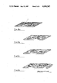
FIG. 7 illustrates video signals of a channel corrected by a side slip angle, with a moving target in the direction of flight and opposite thereto, respectively.
DETAILED DESCRIPTION OF A PREFERRED EMBODIMENT
Referring to the drawings in detail, FIG. 1 illustrates a reconnaissance flight body, in this case, a plane 1 flying over an object of interest, in this case, a tank 2. The latter stands out from its surroundings because of its radiation signature which is utilized by the plane for the measuring method according to the present invention.
For this purpose, the bottom side of the plane is provided with a sensor-system 7, 7' (FIG. 3) covered by the body of the plane. It consists either of two similar receiving elements arranged in series or of two correspondingly built charge coupled device (CCD) picture sensors. These are special semi-conductor building blocks which, however, are commercially available. The scene and the object are scanned strip-like and time-displaced transverse to the axis 25 of the plane. The example shows the bottom side illustration 6,6' or 26,26' respectively of the sensor system which, in the front area of the plane, consists of a serial arrangement 7 with n receiving elements, and, in the rear area of the plane, of a serial arrangement 7' with m receiving elements. In other words, the ground surface overflown by plane 1 is scanned in a strip-like manner and with a relative time delay by means of the two serial arrangements 7 and 7' of receiving elements. The resultant picture strips 6 and 6' are divided into n or m picture elements of the same solid angle, and the longitudinal directions of view of the two serial arrangements of receiving elements are off-set with respect to each other by the constant plane sensor angle ε, with the apex in the sensor. It follows from this, that a stationary tank is registered by the serial arrangement 7 with the coordinates x, y-a and the same tank location by the serial arrangement 7' with a time delay with the coordinates x', y'+b, because of the resultant side-slip angle (equalling the vectorial sum of the side-slip angle and the median roll angle speed.) FIG. 1 also shows, by means of the two arrows pointing in the direction of flight, the plane movement vector 24 and the plane axis 25. The delayed signals of the individual receiving elements of the serial arrangement 7 are correlated with the non-delayed signals of the serial arrangement 7' in the longitudinal (time) axis and the transverse axis, relative to the direction of flight, until they match to a maximum degree. The time which passes until the signals of the serial arrangement receiving element 7 match the momentary signals of the arrangement 7' is a measure of the speed of the plane over ground.
FIG. 2 illustrates that when taking into consideration the altitude H above ground, the pitch angle α of plane 1 and the distance S resulting from the angle ε the speed above ground vg can be determined as follows:
S=H x cos α[tan (ε+α)-tan α] (1)
The speed above ground, vg is the product of the delayed time tv and S:
v.sub.g =t.sub.v x S (2)
Because of the transverse offset of the signals of the receiving element series arrangement 7' up to the best correlation, the resultant side slip angle β visible from FIG. 1, is determined. If one assumes P to be the number of receiving elements in the series arrangement 7' which corresponds to the signal displacement or offset, and θ represents the angle of the field of vision, in rad, of the individual receiving element, th result is:
tanβ=S.sub.trans /S=P xθx H/S (3)
As shown in FIG. 1, as soon as the plane 1 flies over the tank 2 moving in the direction of flight, the momentary delay time tv is changed momentarily by Δtv . Substituting now in equation (2)Δtv instead of tv , the speed of the tank in longitudinal direction can be determined. If the tank also has a speed component in transverse direction, the P-value momentarily changes by ΔP. Substituting in equation (3) ΔP instead of P, one obtains the section ΔStrans in the time tv +Δtv) in which ΔP, Δtv and ΔStrans carry a plus or minus sign. This then results in:
v.sub.trans =S.sub.trans /(t.sub.v +Δt.sub.v) (4)
The altitude above ground H in equations (1) to (4) can, for instance, be determined by a standard radar installation of the plane. However, because of the limited resolution capacity and the large transmitter beam angle, radar is unsuitable for determining the exact momentary altitude. Instead, as shown in the block diagram of FIG. 3, a laser altimeter 16 is used which is characterized by a high distance resolution, narrow focusing and an exact orientation capability. The pitch angle α (FIG. 2) and the roll angle are preferably determined by a compass 17 of the navigational system of the plane, and are fed to a control computer interface unit 18 (FIG. 3) of a multi-function sensor 3. By taking the roll speed into account, the correlation period can be shortened. The use of the laser altimeter 16, and the compass 17, assures a fully self-sufficient operation of the multifunction sensor 3.
In detail the block diagram of FIG. 3 clarifies the following functional procedure:
The tank and its direction of movement is symbolized by the arrow 2, the radiation emitted by the tank reaches the series arrangements 7 and 7' of receiving elements via a common interference filter 4 and a likewise common objective 5. The bottom side scanning strips 6 and 6' of these series arrangements are indicated by dot-dash lines. In another embodiment, not illustrated in the drawing, it is, of course, possible to provide each series arrangement of receiving elements with a separate interference filter for improving the signal/noise conditions and to provide a separate objective. The signals output by the series arrangements are amplified in pre-amplifiers 9 and 9' and are passed on to the multi-plexers 10 and 10'. A control device 8 common to both pre-amplifiers and arranged between their outputs and a respective separate input, controls their amplification with high synchronization accuracy, depending on the "evaluated" signal amplitudes in order to assure an optimum sensitivity of the system. "Evaluated" in this connection, means that the signal amplitudes are calculated not linearly but according to a given function. The signals interrogated via the multiplexers 10 and 10' are passed on to mean value calculators 11 and 11' within the time interval of interrogation. Thereafter, an analog/digital conversion takes place in the analog/digital converters 12 and 12' so that, subsequently, porcessing via digital components is possible. Thereafter, a different processing of the signals takes place in the two channels 7 to 12 and 7' to 12' respectively. As evident from FIG. 4, those in analog/digital convertor 12, are continuously input in the form of a band into a shift register 13 and placed in intermediate storage. The top curve in FIG. 4 represents the signal at the exit of convertor 12 and the lower curve that at the exit of convertor 12', plotted over time t. The number of band signatures to be stored maximally corresponds to the maximum delay time tv +Δt divided by the band scanning interval.
By contrast, the signals converted by the analog/digital converter 12', are put into intermediate storage in register 13' only for one band scanning interval. Within the time interval of registers 13 and 13', a two-plane correlation is carried out in unit 14 (FIG. 3) common to both channels 7 to 12 and 7' to 12', respectively. The amount of data to be correlated is limited by setting a two-dimensional data window 20 (FIG. 4), depending on the range of speed, altitude, pitch angle, and resultant slide slip angle of the plane, as well as on the vectorial target speed range is set, and that, in addition, by optimizing the location of the correlation window in transverse direction via the roll speed.
The coordinates x, y of the best possible correlated picture elements of channels 7 to 13, together with the actual data of channels 7' to 13', are fed from the two-plane correlator 14 to the control computer interface unit 18. These data are averaged over a predetermined time interval because of temporary V (H) measuring errors due to movable targets. Since, as has been mentioned already above, information regarding the altitude, pitching, and rolling angles reach the control computer interface unit 18 via the compass 17, the exact above ground speed of the plane can be determined.
By simple subtraction of the amplitude values of the best possible correlated picture elements of channels 7 to 13, and the associated channels 7' to 13', in this way, always a differential signal signature is obtained when an object flown over has moved in between these scanning operations. From the course of this differential signal signature over time, while making use of the directly obtained above ground speed and altitude, the real vectorial speed of the tank can be calculated.
In order to determine also the side slip angle β shown in FIGS. 1 and 4, the serial arrangements 7 and 7' may be composed of a different number of receiving elements. Preferably, the number of elements in serial arrangement 7 is larger than that in 7'. In these figures, L designates half the difference in length.
FIG. 5 assumes an increase in the signal of the tank compared to its environment. This corresponds, for instance, in the infrared range, to a higher radiation or temperature of tank 2 and of a building designated with the reference numeral 2', compared to the environment. The course of the differential signal, first negative and then positive, the plus or minus sign of the speed component of the tank in the direction of flight is given. In detail, in FIG. 5a, the non-delayed signal of channel 7 to 12 is illustrated. FIG. 5b shows the same signal which, however, has been delayed by the shift register 13 (FIG. 4). In FIG. 5c, there is shown the signal of channel 7' to 12', which is scanned slightly later. One recognises that the position of the tank 2 relative to building 2', in the direction of view, has changed towards the right picture margin. From FIG. 5d the differential signal signature is evident in which from the delayed signal of the first mentioned channel, the momentary signal of the other has been subtracted.
Similar comments apply to FIG. 6, which represents the differential signal, if the tank 2 has moved transverse to the direction of flight. Also, in this figure, it is evident that the course of the differential signal determines the sign (+ or -) of the transverse speed component of the tank.
FIG. 7 shows the video signals of the channel corrected with the resultant slide slip angle β for a tank which moves in the direction of flight, or opposite thereto. The differential signal signature of a tank at rest is equal to zero. In FIG. 7a, again, the non-delayed signal is shown, and in FIG. 7b, the signal delayed by the interval tv and corrected with the resultant slide slip angle of channel 7 to 12. FIG. 7c, on the other hand, shows the signal of channel 7' to 12' is subsequent in time. The course of the signal curve shown in FIG. 7d, which first is positive and then negative, leads to the conclusion that the movement of the tank took place in the direction of flight. The time interval between the signal which is first positive and then negative, is +Δtv and thereby, proportional to the speed component of the tank in the direction of flight.
On the other hand, if the curve of the delayed signal of channel 7' to 12' is as shown in FIG. 7e, a differential signal occurs between curves 7b and 7e, as evident from FIG. 7f. One recognizes the course of the curves, first negative and then positive, in comparison to FIG. 7d. The time interval of the first negative and then positive course of the signal is now -Δtv and gives a tank movement opposite to the direction of flight and with a speed component proportional to -Δtv.
Similar to FIG. 7, other video signals for determining the transverse speed of a tank can be illustrated. In this cases, instead of Δtv, only that number of receiving elements of serial arrangement 7' is determined which extends over the width of the positive or negative signal curve, according to FIG. 7d. The transverse speed com onent of the tank can then be calculated from the equations (3) and (4), the sign (positive or negative) is predetermined by the polarity course of the curve of the differential signal.
In a manner known per se, the vectorial speed can be determined from the longitudinal and the transverse speed components.
The signals scanned by the multiplexers 10 and 10' of the serial arrangements 7 and 7' of the receiving elements can also be used for a line scanner for a picture or a scanning pattern of the ground.