US468468A - Island - Google Patents
Island Download PDFInfo
- Publication number
- US468468A US468468A US468468DA US468468A US 468468 A US468468 A US 468468A US 468468D A US468468D A US 468468DA US 468468 A US468468 A US 468468A
- Authority
- US
- United States
- Prior art keywords
- drill
- dies
- grooves
- rolling
- drills
- Prior art date
- Legal status (The legal status is an assumption and is not a legal conclusion. Google has not performed a legal analysis and makes no representation as to the accuracy of the status listed.)
- Expired - Lifetime
Links
- 238000005096 rolling process Methods 0.000 description 7
- 230000006872 improvement Effects 0.000 description 4
- 241000220010 Rhode Species 0.000 description 2
- 230000009471 action Effects 0.000 description 2
- 239000002184 metal Substances 0.000 description 2
- 230000007246 mechanism Effects 0.000 description 1
- 238000000034 method Methods 0.000 description 1
- ONCZDRURRATYFI-QTCHDTBASA-N methyl (2z)-2-methoxyimino-2-[2-[[(e)-1-[3-(trifluoromethyl)phenyl]ethylideneamino]oxymethyl]phenyl]acetate Chemical compound CO\N=C(/C(=O)OC)C1=CC=CC=C1CO\N=C(/C)C1=CC=CC(C(F)(F)F)=C1 ONCZDRURRATYFI-QTCHDTBASA-N 0.000 description 1
- 238000003825 pressing Methods 0.000 description 1
- 230000008569 process Effects 0.000 description 1
Images
Classifications
-
- B—PERFORMING OPERATIONS; TRANSPORTING
- B21—MECHANICAL METAL-WORKING WITHOUT ESSENTIALLY REMOVING MATERIAL; PUNCHING METAL
- B21B—ROLLING OF METAL
- B21B1/00—Metal-rolling methods or mills for making semi-finished products of solid or profiled cross-section; Sequence of operations in milling trains; Layout of rolling-mill plant, e.g. grouping of stands; Succession of passes or of sectional pass alternations
- B21B1/16—Metal-rolling methods or mills for making semi-finished products of solid or profiled cross-section; Sequence of operations in milling trains; Layout of rolling-mill plant, e.g. grouping of stands; Succession of passes or of sectional pass alternations for rolling wire rods, bars, merchant bars, rounds wire or material of like small cross-section
- B21B1/163—Rolling or cold-forming of concrete reinforcement bars or wire ; Rolls therefor
-
- Y—GENERAL TAGGING OF NEW TECHNOLOGICAL DEVELOPMENTS; GENERAL TAGGING OF CROSS-SECTIONAL TECHNOLOGIES SPANNING OVER SEVERAL SECTIONS OF THE IPC; TECHNICAL SUBJECTS COVERED BY FORMER USPC CROSS-REFERENCE ART COLLECTIONS [XRACs] AND DIGESTS
- Y10—TECHNICAL SUBJECTS COVERED BY FORMER USPC
- Y10T—TECHNICAL SUBJECTS COVERED BY FORMER US CLASSIFICATION
- Y10T408/00—Cutting by use of rotating axially moving tool
- Y10T408/03—Processes
Definitions
- This invention relates to the rotary sidedies used in machines for rolling twist-drills .in the manner as disclosed in the United States Patent No. 432,395, of July 22, 1890.
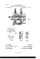
- Figure 1 is a vertical section of a part of the machine shown in the patent above referred to, representing the circular side dies as used in that machine, with a section of a drillblank in the dies.
- Fig. 2 is an enlarged representation of the dies for rolling the main grooves in the drill and parts of the side dies with a section of a drill-blank between them.
- Fig. 3 shows the shape of the different rolled surfaces after the drill has been twisted to a spiral form.
- Fig. 4 represents a side View of a part of a drill with one of the main grooves in front.
- Fig. 5 is a side view of a part of a drill after rolling and before being made spiral, showing one of the sides rolled by a side die. 7
- a twist-drill-rolling machine represented in Fig. 1 consists of two arbors B B, held one above the other in adjustable bearings between suitable standards g g.
- Blocks 'r r adjustable laterally, are placed between said standards and arbors and have recesses made in them to hold the side dies d d, which revolve on pivots t 25, passing vertically through the blocks and dies.
- This figure is introduced mainly to identify the side dies and for the purpose of showing their positionswith regard to each other, to the other parts of the machine, and to the work operated on when used.
- the improvement con-- 50 sists in making a shallow circular V-shaped recess in the periphery of each die.
- These side dies d are circular plates held on pivots in the blocks 1- 0", which, as above stated, are adjustable laterally for the purpose-of moving the dies nearer to or farther from the center occupied by the drill-blank.
- This groove starts at n a short distance in on the face of the die (see Fig. 2) and runs in a straight line to the center o of the face at angle of about seven degrees to it, and thence at same angle to a point a at the same distance from the other side.
- These two faces ct a of the dies d. make the two fiat faces a a on the sides of the drillblank f; but twisting the drill into a spiral form makes these faces a concave, as seen in Fig.
- the side dies (1 d depend entirely on the impact of their faces upon the blank as it is rolled out by the dies 1) b to turn them,the swaging action of dies 12 Z) pressing the blank sidewise into the side dies.
Landscapes
- Engineering & Computer Science (AREA)
- Mechanical Engineering (AREA)
- Drilling Tools (AREA)
Description
(No Model.)
A. B. SHIPPEE. MACHINE FOR MAKING TWIST DRILLS.
No. 468,468. Patented Feb. 9, 18912.
III I WI NEEEEE.
Unrrnn STATES PATENT OFFICE.
AARON l3. SI'IIPPEE, OF PROVIDENCE, RHODE ISLAND, ASSIGNOR TO ALBERT V. CHAPMAN, OF SAME PLACE.
MACHINE FOR MAKING TWIST-DRILLS.
SPECIFICATION forming part of Letters Patent No. 468,468, dated February 9, 1892..
Application filed September 21,1891. Serial No. 406,315. (No model.)
To aZZ whom it may concern:
Be it known that I, AARON B. SHIPPEE, of Providence, in the county of Providence and State of Rhode Island, have invented certain new and useful Improvements in Machines for Making Twist-Drills; and I do hereby declare that the following is a full, clear, and exact description thereof, reference being had to the accompanying drawings, and to the letters of reference marked thereon, which form a part of this specification.
This invention relates to the rotary sidedies used in machines for rolling twist-drills .in the manner as disclosed in the United States Patent No. 432,395, of July 22, 1890.
It consists, mainly, in an improvement in the working faces of those dies.
It is fully illustrated in the accompanying drawings.
Figure 1 is a vertical section of a part of the machine shown in the patent above referred to, representing the circular side dies as used in that machine, with a section of a drillblank in the dies. Fig. 2 is an enlarged representation of the dies for rolling the main grooves in the drill and parts of the side dies with a section of a drill-blank between them. Fig. 3 shows the shape of the different rolled surfaces after the drill has been twisted to a spiral form. Fig. 4 represents a side View of a part of a drill with one of the main grooves in front. Fig. 5 is a side view of a part of a drill after rolling and before being made spiral, showing one of the sides rolled by a side die. 7
The part of a twist-drill-rolling machine represented in Fig. 1 consists of two arbors B B, held one above the other in adjustable bearings between suitable standards g g. Blocks 'r r, adjustable laterally, are placed between said standards and arbors and have recesses made in them to hold the side dies d d, which revolve on pivots t 25, passing vertically through the blocks and dies. This figure is introduced mainly to identify the side dies and for the purpose of showing their positionswith regard to each other, to the other parts of the machine, and to the work operated on when used. The improvement con-- 50 sists in making a shallow circular V-shaped recess in the periphery of each die. These side dies d are circular plates held on pivots in the blocks 1- 0", which, as above stated, are adjustable laterally for the purpose-of moving the dies nearer to or farther from the center occupied by the drill-blank. This groove starts at n a short distance in on the face of the die (see Fig. 2) and runs in a straight line to the center o of the face at angle of about seven degrees to it, and thence at same angle to a point a at the same distance from the other side. These two faces ct a of the dies d. make the two fiat faces a a on the sides of the drillblank f; but twisting the drill into a spiral form makes these faces a concave, as seen in Fig. 3, by the raising of the edges 1', as in twisting a square bar of metal the sides are made concave. This produces the shape as shown in section in Fig. 3,the dotted circle .9 representing the original outline of the bar before rolling. The shallow V-grooves represented by the faces ct in the side dies also hold the drill-blank steadily in the center of the four dies until the two dies 1) b, which form the main grooves in the drill, strike the blank and roll it out from between them as they form the grooves. The side dies d d by the ridges r r, Fig. 3, which they form on the sides of the drill, prevent the drill from turning on its center, while the dies 1) I) roll the deep grooves in the drill. This has the effect of producing drills with perfectly-straight grooves. The side dies (1 d depend entirely on the impact of their faces upon the blank as it is rolled out by the dies 1) b to turn them,the swaging action of dies 12 Z) pressing the blank sidewise into the side dies. The shallow grooves thus produced on the sides of the drill by the action of the side dies and the process of twisting, besides relieving the outside of 0- the drill, serve an important purpose in conveying the oil to the inner end of the drill,as they are too shallow to receive the chips made in boring, the rush of which along the main grooves c c sweeps the oil back and effectu- 9 5 ally prevents it from reaching the inner end Where the cutting of the metal is being done without the whole passage is kept flooded with oil.
The usual way of relieving the outside of I00 the drill by sloping it away from the forward or cutting edge of the drill to the back edge of the wing only offers more facility for the oil put on the outside of the drill to be carried by the rotary motion of the drill or work into the main grooves c to be brushed out back with the chips as they are delivered.
v Having thus described my improvements and set forth the advantages derived from :0 them, I claim as my invention- In a machine for rolling twist-drills, two rotating side dies having shallow V-shaped grooves made in their peripheries, substantially as described, in combination with ro-- tating dies for rolling the main grooves and r 5 mechanism for operating them.
A. B. SI-IIPPEE. Witnesses:
BENJ. ARNOLD, CHARLES HANNIGAN.
Publications (1)
| Publication Number | Publication Date |
|---|---|
| US468468A true US468468A (en) | 1892-02-09 |
Family
ID=2537329
Family Applications (1)
| Application Number | Title | Priority Date | Filing Date |
|---|---|---|---|
| US468468D Expired - Lifetime US468468A (en) | Island |
Country Status (1)
| Country | Link |
|---|---|
| US (1) | US468468A (en) |
-
0
- US US468468D patent/US468468A/en not_active Expired - Lifetime
Similar Documents
| Publication | Publication Date | Title |
|---|---|---|
| US1875362A (en) | The method of fo | |
| US302600A (en) | stetson | |
| US238953A (en) | Manufacture of twist-drills | |
| US223730A (en) | harvey | |
| US260196A (en) | Rolling-mill | |
| US468469A (en) | Island | |
| US228485A (en) | William a | |
| US518205A (en) | Island | |
| US439951A (en) | Thomas c | |
| US137009A (en) | Improvement in the manufacture of bolts and rivets | |
| US515376A (en) | Island | |
| US431925A (en) | Island | |
| US365980A (en) | Faiebairn | |
| US370354A (en) | Chaeles d | |
| US282377A (en) | Assig-nob to | |
| US675958A (en) | Milling-cutter. | |
| US175426A (en) | Improvement in machines for threading and pointing screw-blanks | |
| US136620A (en) | Improvement in machines for rolling carriage-axles | |
| US440330A (en) | Island | |
| US248167A (en) | Process of threading screws | |
| US146212A (en) | Improvement in dies for forming auger-bits | |
| US371015A (en) | Island | |
| US64447A (en) | of worcester | |
| US189112A (en) | Improvement in machines for making horseshoe-nails | |
| US375097A (en) | eogers |