US468373A - Cotton-harvester - Google Patents
Cotton-harvester Download PDFInfo
- Publication number
- US468373A US468373A US468373DA US468373A US 468373 A US468373 A US 468373A US 468373D A US468373D A US 468373DA US 468373 A US468373 A US 468373A
- Authority
- US
- United States
- Prior art keywords
- cotton
- shaft
- picker
- apron
- stems
- Prior art date
- Legal status (The legal status is an assumption and is not a legal conclusion. Google has not performed a legal analysis and makes no representation as to the accuracy of the status listed.)
- Expired - Lifetime
Links
- 238000010276 construction Methods 0.000 description 6
- 229920000742 Cotton Polymers 0.000 description 3
- 238000010168 coupling process Methods 0.000 description 2
- 238000005859 coupling reaction Methods 0.000 description 2
- 230000002452 interceptive effect Effects 0.000 description 2
- 238000004140 cleaning Methods 0.000 description 1
Images



Classifications
-
- A—HUMAN NECESSITIES
- A01—AGRICULTURE; FORESTRY; ANIMAL HUSBANDRY; HUNTING; TRAPPING; FISHING
- A01D—HARVESTING; MOWING
- A01D46/00—Picking of fruits, vegetables, hops, or the like; Devices for shaking trees or shrubs
- A01D46/08—Picking of fruits, vegetables, hops, or the like; Devices for shaking trees or shrubs of cotton
- A01D46/14—Picking of fruits, vegetables, hops, or the like; Devices for shaking trees or shrubs of cotton using lint-from-plant pickers
Definitions
- mc mums varias cu., mow-uma., mwmucn, n, c.
- This invention relates to improvements in cotton-harvesters in which the picker-stems are caused to have simultaneously an individual axial rotation and a bodily travel about two or more axes or centers of revoluion.
- the prime object of this invention is to irnpart to said picker-stems so operated an axial rotation faster than their bodily travel about the axis of their support.
- Another object is to have the picker-stems journaled in a horizontally-traveling apron and actuated in such manner as to have an individual axial rotation faster than their bodily travel with said apron and faster than is possible where the picker-stems depend solely upon the travel of the apron for their axial rotation.
- a further object is to have each of the slats of the apron constitute an oil-chamber for automatically and continuously oiling the bearings of all of the picker-stems journaled therein.
- a still further object is to have the frame of the machine, upon which the traveling apron is supported, adjustable in such Inanner that the apron may be bodily adjusted vertically while in a horizontal position, or the ends thereof may be independently adjusted, so as to cause the apron to operate in an inclined position.
- A indicates the body or mainframe of my machine, constituting a cotton-receptacle and supported at its forward end upon a crank-axle B, as in my aforesaid case, upon the crank ends C of which axle are mounted the main ground or drive wheels D, by means of which power is imparted to the operating mechanism of my machine.
- a vertical adjustment of the forward end of the machine is obtained by means of a gearwheel E, mounted upon the ends of the main portion of the crank-axle, but secured to the angular portions thereof and meshing with worms F, secured to the lower end of vertical shafts G, journaled in suitable brackets at each side of the machine, which shafts are provided with beveled gears Il on the upper ends thereof, and are caused to rotate simultaneously by means of a horizontal crankshaft I, upon the ends of which are fixed beveled gears J, meshing with the gears I-I upon the said shaft, one of which is extended above said gears and provided with a crank-handle K for imparting a rotary motion thereto.
- crank portion of the axle normally lies in the same horizontal plane with the body portion thereof and that any movement of the body IOD portion must cause the frame of the machine to move vertically on the are of a circle to- Ward or away from the ground.
- the rear end of the machine is supported upon casterwheels L, which, however, are not vertically movable independent of the frame of the machine, as in the aforesaid application; but they are vertically adjustable with relation to the body of the machine by means of vthe standard M thereof, having a sliding connection with a guide N, secured to the end wall of the frame, with which standard a vertical rod O has a screw-thread connection,working through an eye P upon the frame, but prevented from having endwise or longitudinal movement through said eye by means of collars Q thereon above and below the eye, permitting a free rotation thereofthrough the crank-handle R, which causes the standard to slide vertically, and thus permit of a vertical adjustment of the frame relative to the ground.
- the picker-stem support in this machine is an endless horiZontally-traveling apron consisting of a series of tubular slats S, preferably square in cross-section and connected together by means of links T, extending from the ends thereof in each direction, the links of adjacent slats having a pivotal connection with each other.
- This sleeve is driven by a sprocket-wheel g upon the outer end thereof, around which and around a corresponding sprocket-wheel h upon an axle extension of the main body of the crank-axle works a sprocket-chain t', the sprocket-wheel h having a cog-Wheel j cast with or rigidly secured thereto, with which meshes an intermediate spur-gear 7s, driven by a cog-wheel Z, secured to the hub of one of the ground-wheels.
- each of the picker-stems is ser cured a pinion u, meshing With a corresponding beveled gear t1, fixed upon a line-shaft w, underlying and traveling With'the slat, being journaled in depending brackets or bearings a; at the center and each end of the slat and having one of the gears fu for each picker-stem.
- the line-shaft w is driven by means of a cog-wheel y on one end thereof, meshing with a corresponding cog-wheel e', cast with or rigidly mounted upon the inner end of the short shaft m, upon the outer end of which, beyond the roller o, is rigidly secured a drive cog-Wheel 1, engaging and operated by an oblong cog-rack 2, formed upon the oblong guide-plate 1),.parallel with the tracks upon which the rollers 0 travel, so that when the apron is caused to travel a 1'0- tary motion at a high rate of speed will be imparted to the picker-stems through the medium of the gearing intermediate said stems and the stationary rack and at aspeed faster than the bodily travel of the pickerstems with the apron or than is possible to attain where the picker-stem gears are directly actuated by the oblong cog-racks and depend solely upon the travel with the apron for their speed of
- interlocking shields 3 projecting laterally from each side of the slats, with To the inner end of l IIO the ends overlapping, so that the surface of the apron as a whole is practically continuous.
- the mechanism for removing the gathered cotton from the pickerstern-that is, the cleaner device- is identical in construction and operation with that of the aforesaid application, and consists of a series of disks or hubs 5, secured upon a rotatablehollow shaft 6, sleeved upon a tie-rod 7, from each of which disks project a series of radial arms 8, the opposing surfaces of which are covered with bristles 9 and betweeneach pair of which the picker-stems aro passed in series during their travel.
- a rotary motion is imparted to said shaft by means of a cog-wheel l0, secured to one end thereof and meshing with another cog-wheel 1l, mounted upon the inner end of a short horizontal shaft 12, to the outer end of which is secured a pinion i3, driven by a larger cog-wheel 14, :rigidly mounted upon a sleeve l5 on the end of the cross-shaft e, between which sleeve and shaft there is an ordinary clutch-coupling 16 for controlling the operation thereof.
- the shaft e is driven by a duplication of the gearing employed for driving, the hollow drive-shaft of the picking mechanism, and the corresponding parts are lettered in the drawings g', h', thj, k', and l', the operation of which has been already described.
- a cotton-harvester the combination, with a series of tubular picker-stem supports, a link connection therebetween, said tubes constituting oil-chambers, a series of rotatable picker-stems bearing in and projecting through said tubular support, a line-shaft journaled upon and lying parallel with each of said supports, and a gear connection between said shaft and the series of pickerstems, of mechanism for traveling said supports about two or more centers and means for rotating said line-shaft, substantially as described.
- a cotton-harvester the combination, with a series of picker-stem supports, a link connection therebetween, a series of rotatable picker-stems bearing in and projecting through said supports, a line-shaft journaled upon and lying parallel with each of said supports, and a gear connection between said shafts and the series of stems, of guide-plates opposing the ends of said supports, having guideways therein, a cog-rack formed on one of said guide-plates, rollers upon the ends of said supports working in the guideways, and a gear connection between said cog-rack and each of the line-shafts, substantially as described.
- a cotton-harvester the combination, with a series of picker-stem supports having a link connection therebetween and provided with pivoting-studs on the ends thereof, means for traveling said supports about two or more axes, short shafts provided with axial sockets for reception of said stud, gear-wheels upon each end of said shafts, and a stationary oblong cog-rack engaged by and driving one of said gears, of a guidewayparallel with said racks, supporting-rollers loosely journaled on said shafts and traveling in said guideways, a series of picker-stems journaled in and projecting through each of said supports, alineshaft journaled upon and lying parallel with each of said supports, and a gear upon the endof said shafts meshing with the gear upon the inner end of the short shaft,substantially as described.
Landscapes
- Life Sciences & Earth Sciences (AREA)
- Environmental Sciences (AREA)
- Harvesting Machines For Root Crops (AREA)
Description
(No Model.) 4 SheetsSheet 1.
G. N. TODD. COTTON HARVESTER.
Patented Peb. 9, 1892.
(No Model.) 4 Sheets-Sheet 2. G `N TODD COTTON HARVESTER.
Pau-,wm Feb. 9, 1892.
4 Sheets-Sheet .3.
(No Model.)
G.N.T0D D. COTTON HARVESTER.
Patented Peb. 9, 1892.
4 Sheets-Sheet 4. G. N. TODD. COTTON HARVESTER.
`(No Model.)
No. 468,373. Patented Peb. 9, 1892.
I LILILH.. r
mc mums varias cu., mow-uma., mwmucn, n, c.
v UNITED STATES PATENT OFFICE.
GEORGE N. rlODD, OF CHICAGO, ILLINOIS.
COTTON-HARVESTER.
SPECIFICATION forming part of Letters Patent No. 468,373, dated February 9, 1892.
Application tiled September 17,1889. Serial No. 324,176. (No model.)
To @ZZ whom t may concern:
Beit known that I, GEORGE N. TODD, a citizen of the United States, and a residentof Chicago, in the county of Cook and State of Illinois, have invented certain new and useful Improvements in Cotton-Harvesters, of which the following is a specification.
This invention relates to improvements in cotton-harvesters in which the picker-stems are caused to have simultaneously an individual axial rotation and a bodily travel about two or more axes or centers of revoluion.
The prime object of this invention is to irnpart to said picker-stems so operated an axial rotation faster than their bodily travel about the axis of their support.
Another object is to have the picker-stems journaled in a horizontally-traveling apron and actuated in such manner as to have an individual axial rotation faster than their bodily travel with said apron and faster than is possible where the picker-stems depend solely upon the travel of the apron for their axial rotation.
A further object is to have each of the slats of the apron constitute an oil-chamber for automatically and continuously oiling the bearings of all of the picker-stems journaled therein.
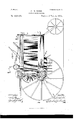
A still further object is to have the frame of the machine, upon which the traveling apron is supported, adjustable in such Inanner that the apron may be bodily adjusted vertically while in a horizontal position, or the ends thereof may be independently adjusted, so as to cause the apron to operate in an inclined position. These objects are attained by the devices illustrated in the accompanying drawings, in which- Figure l represents a side elevation of a cotton-harvester embodying` my invention, showing the near drive-wheel removed; Fig. 2, a similar view taken from the opposite side of the machine; Fig. 3, a cent-ral longitudinal section through the machine; Fig. l-, a transverse vertical section thereof on the line 4: et of Fig. 3; Fig. 5, an enlarged detailed section through one end of the apron and its operating mechanism, taken on the same line as Fig. 4; Fig. G, an enlarged side elevation of the apron-frame with parts broken away to more clearly disclose the construction and relative location of the ap ron-operating mechanism, and Fig. 7 an enlarged detailed section through one of the apron-slats and the picker-stein bearing therein. i
Similar letters and numerals of reference indicate the same parts in the several figures of the drawings.
The general features of construction and operation of thisjmachine are similar to those of another application filed by me of even date herewith, Serial No. 324,1 7 5, the main feature of difference being the construction and operation of the cotton-picking devices, and for that reason need onlyhave a general mention herein.
Referring by letters and figures to the accompanying drawings, A indicates the body or mainframe of my machine, constituting a cotton-receptacle and supported at its forward end upon a crank-axle B, as in my aforesaid case, upon the crank ends C of which axle are mounted the main ground or drive wheels D, by means of which power is imparted to the operating mechanism of my machine.
A vertical adjustment of the forward end of the machine, as in the aforementioned application, is obtained by means of a gearwheel E, mounted upon the ends of the main portion of the crank-axle, but secured to the angular portions thereof and meshing with worms F, secured to the lower end of vertical shafts G, journaled in suitable brackets at each side of the machine, which shafts are provided with beveled gears Il on the upper ends thereof, and are caused to rotate simultaneously by means of a horizontal crankshaft I, upon the ends of which are fixed beveled gears J, meshing with the gears I-I upon the said shaft, one of which is extended above said gears and provided with a crank-handle K for imparting a rotary motion thereto. rlhus whenever the worms are operated through said handle the main body portion of the crank-axle, and consequently the forward end of the frame of the machine, will be caused to swing about the axis of the crank portions of the axle-bearing in the hub of the drive-wheel, it being understood that the crank portion of the axle normally lies in the same horizontal plane with the body portion thereof and that any movement of the body IOD portion must cause the frame of the machine to move vertically on the are of a circle to- Ward or away from the ground. The rear end of the machine is supported upon casterwheels L, which, however, are not vertically movable independent of the frame of the machine, as in the aforesaid application; but they are vertically adjustable with relation to the body of the machine by means of vthe standard M thereof, having a sliding connection with a guide N, secured to the end wall of the frame, with which standard a vertical rod O has a screw-thread connection,working through an eye P upon the frame, but prevented from having endwise or longitudinal movement through said eye by means of collars Q thereon above and below the eye, permitting a free rotation thereofthrough the crank-handle R, which causes the standard to slide vertically, and thus permit of a vertical adjustment of the frame relative to the ground. By this vertically-adjustable support of the two ends of the frame of the machine tlie latter may be adjusted bodily and vertically relative to the ground while in a horizontal position, or either end thereof may be adjusted independent of the other, so' as to cause the frame to stand in an inclined position, without in the least interfering with the operation of the cotton picking and cleaning devices supported thereon.
The picker-stem support in this machine is an endless horiZontally-traveling apron consisting of a series of tubular slats S, preferably square in cross-section and connected together by means of links T, extending from the ends thereof in each direction, the links of adjacent slats having a pivotal connection with each other. These slats are operated by and travel about the axis of two pairs of sprocket-Wheels U, one pairof which is keyed upon a hollowr shaft V, sleeved upon the main portion of the crank-axle, While the other pair is loosely journaled upon a cross-shaft WV, bearing at its endsin theside wallsof the frame of the machine, about the center of length thereof, and in a horizontal plane with the normal position of the crank-axle, a rotary motion being imparted to said hollow shaft or sleeve by substantially the same mechanism as is employed for operating the drum of my aforesaid application, consisting of a sprocketwheel a, keyed upon the sleeve at one end thereof and driven by a sprocket-chain h, working over another sprocket-wheel c, loosely mounted upon a sleeve d upon a cross-shaft e at the top of the machine, between which sleeve and wheel there is a spring-actuated clutch-coupling f, of the usual construction of such devices. This sleeve is driven by a sprocket-wheel g upon the outer end thereof, around which and around a corresponding sprocket-wheel h upon an axle extension of the main body of the crank-axle works a sprocket-chain t', the sprocket-wheel h having a cog-Wheel j cast with or rigidly secured thereto, with which meshes an intermediate spur-gear 7s, driven by a cog-wheel Z, secured to the hub of one of the ground-wheels.
Within the links T of the apron is loosely journaled a short shaft fm, provided with an axle-socket on the inner end thereof, into which projects a stud-bearing n from the tubular slat, said shaft being in turn supported upon a roller o, located outside of the links and the sprocket-Wheels U, rotating freely upon said shaft and traveling in a groove or guideway formed on the inner face of oblong plates 1J, which have an outline corresponding to thetravel of the apron-that is to say, they are straight along their upper and lower surfaces, and formed on the arc of a circle struck from the axis of the sleeve V and shaft YV, so that when thelinks are actuated through the medium of the sprocket- Wheel U the apron, the slats of which are individually supported at each end upon the roller o, will be caused to traverse `its orbit.y In each of the slats and projecting at a right angle from the outer face thereof is arranged a longitudinal series of picker-stems q, the picking-surface of which may be of any desirable construction' and the journals r of which work in suitable bearings s, extending throughthe oilchamber of the slat and screwed at its ends into the inner and outer walls of the slat, the said bearing being provided with oil passages or ducts t, leading from the oil-chamber tothe internal bearingsurface thereof, so that the journals of the picker-stems will be continuously and automatically lubricated. the journal of each of the picker-stems is ser cured a pinion u, meshing With a corresponding beveled gear t1, fixed upon a line-shaft w, underlying and traveling With'the slat, being journaled in depending brackets or bearings a; at the center and each end of the slat and having one of the gears fu for each picker-stem. The line-shaft w is driven by means of a cog-wheel y on one end thereof, meshing with a corresponding cog-wheel e', cast with or rigidly mounted upon the inner end of the short shaft m, upon the outer end of which, beyond the roller o, is rigidly secured a drive cog-Wheel 1, engaging and operated by an oblong cog-rack 2, formed upon the oblong guide-plate 1),.parallel with the tracks upon which the rollers 0 travel, so that when the apron is caused to travel a 1'0- tary motion at a high rate of speed will be imparted to the picker-stems through the medium of the gearing intermediate said stems and the stationary rack and at aspeed faster than the bodily travel of the pickerstems with the apron or than is possible to attain where the picker-stem gears are directly actuated by the oblong cog-racks and depend solely upon the travel with the apron for their speed of rotation.
For the purpose of preventing the cotton from interfering with the operating mechanism I provide interlocking shields 3, projecting laterally from each side of the slats, with To the inner end of l IIO the ends overlapping, so that the surface of the apron as a whole is practically continuous.
The mechanism for removing the gathered cotton from the pickerstern-that is, the cleaner device-is identical in construction and operation with that of the aforesaid application, and consists of a series of disks or hubs 5, secured upon a rotatablehollow shaft 6, sleeved upon a tie-rod 7, from each of which disks project a series of radial arms 8, the opposing surfaces of which are covered with bristles 9 and betweeneach pair of which the picker-stems aro passed in series during their travel. A rotary motion is imparted to said shaft by means of a cog-wheel l0, secured to one end thereof and meshing with another cog-wheel 1l, mounted upon the inner end of a short horizontal shaft 12, to the outer end of which is secured a pinion i3, driven by a larger cog-wheel 14, :rigidly mounted upon a sleeve l5 on the end of the cross-shaft e, between which sleeve and shaft there is an ordinary clutch-coupling 16 for controlling the operation thereof. The shaft e is driven by a duplication of the gearing employed for driving, the hollow drive-shaft of the picking mechanism, and the corresponding parts are lettered in the drawings g', h', thj, k', and l', the operation of which has been already described.
llaving described my invention, what I claim, and desire to secure by Letters Patent, 1sAM l. In a cotton-harvester, the combination, with an endless apron consisting of a series of tubular slats constituting oil-chambers and linked together, of a series of picker-stems journaled in each of said slats, the bearings of which are connected with and constantly oiled from said chamber, substantially as described.
2. In a cotton-harvester, the combination, with an endless traveling apron composed of a series of tubular slats constituting oil-chambers and linked together, of a series of pickerstems and a corresponding series of bearings therefor in each of said slats in which the journals of said stems work, said bearings projecting through the oil-chamber and having a communicating passage leading to the bearingsurface thereof,substantiallyasdescribed.
8. In a cotton-harvester, the combination, with a series of tubular picker-stem supports, a link connection therebetween, said tubes constituting oil-chambers, a series of rotatable picker-stems bearing in and projecting through said tubular support, a line-shaft journaled upon and lying parallel with each of said supports, and a gear connection between said shaft and the series of pickerstems, of mechanism for traveling said supports about two or more centers and means for rotating said line-shaft, substantially as described.
4. In a cotton-harvester, the combination, with a series of picker-stem supports, a link connection therebetween, a series of rotatable picker-stems bearing in and projecting through said supports, a line-shaft journaled upon and lying parallel with each of said supports, and a gear connection between said shafts and the series of stems, of guide-plates opposing the ends of said supports, having guideways therein, a cog-rack formed on one of said guide-plates, rollers upon the ends of said supports working in the guideways, and a gear connection between said cog-rack and each of the line-shafts, substantially as described.
5.In a cotton-harvester, the combination, with a series of picker-stem supports having a link connection therebetween and provided with pivoting-studs on the ends thereof, means for traveling said supports about two or more axes, short shafts provided with axial sockets for reception of said stud, gear-wheels upon each end of said shafts, and a stationary oblong cog-rack engaged by and driving one of said gears, of a guidewayparallel with said racks, supporting-rollers loosely journaled on said shafts and traveling in said guideways, a series of picker-stems journaled in and projecting through each of said supports, alineshaft journaled upon and lying parallel with each of said supports, and a gear upon the endof said shafts meshing with the gear upon the inner end of the short shaft,substantially as described.
GEORGE N. TODD. Witnesses:
R. C. OMOHUNDRO, W. R. OMoHUNDRo.
Publications (1)
| Publication Number | Publication Date |
|---|---|
| US468373A true US468373A (en) | 1892-02-09 |
Family
ID=2537234
Family Applications (1)
| Application Number | Title | Priority Date | Filing Date |
|---|---|---|---|
| US468373D Expired - Lifetime US468373A (en) | Cotton-harvester |
Country Status (1)
| Country | Link |
|---|---|
| US (1) | US468373A (en) |
Cited By (1)
| Publication number | Priority date | Publication date | Assignee | Title |
|---|---|---|---|---|
| US20050119074A1 (en) * | 2003-10-27 | 2005-06-02 | Donald Waite | Basketball backboard |
-
0
- US US468373D patent/US468373A/en not_active Expired - Lifetime
Cited By (1)
| Publication number | Priority date | Publication date | Assignee | Title |
|---|---|---|---|---|
| US20050119074A1 (en) * | 2003-10-27 | 2005-06-02 | Donald Waite | Basketball backboard |
Similar Documents
| Publication | Publication Date | Title |
|---|---|---|
| US3050759A (en) | Brush drive means for cleaning cylindrical surfaces | |
| US796268A (en) | Self-propelling combination harvesting-machine. | |
| US1926337A (en) | Cotton picking mechanism | |
| US1357301A (en) | Oiling system | |
| US1510880A (en) | Sweeper | |
| US662366A (en) | Clod-crusher and sod-cutter. | |
| US195527A (en) | Jsmpjrov | |
| US2224286A (en) | Cotton picker | |
| US777595A (en) | Cotton-harvester. | |
| DE335958C (en) | Motor plow with rotating tools | |
| US106441A (en) | Improvement in rotary steam-plows | |
| US475979A (en) | foote | |
| US1336349A (en) | Sweeper | |
| US416407A (en) | Cotton-harvester | |
| US1259098A (en) | Traction-wheel. | |
| US1737850A (en) | Cotton picker | |
| US365374A (en) | Street-sweeping machine | |
| US863962A (en) | Cotton picking or harvesting machine. | |
| US1586573A (en) | Loading machine | |
| US685440A (en) | Cotton-harvester. | |
| US951721A (en) | Chain driving-gear. | |
| US731465A (en) | Harvester. | |
| US620735A (en) | Traction-engine | |
| US988306A (en) | Spinning-head. | |
| US762585A (en) | Traveling harvester. |