US4669629A - Full-open convenience-feature sheet metal can - Google Patents
Full-open convenience-feature sheet metal can Download PDFInfo
- Publication number
- US4669629A US4669629A US06/854,914 US85491486A US4669629A US 4669629 A US4669629 A US 4669629A US 85491486 A US85491486 A US 85491486A US 4669629 A US4669629 A US 4669629A
- Authority
- US
- United States
- Prior art keywords
- end wall
- metal
- wall panel
- side wall
- flange
- Prior art date
- Legal status (The legal status is an assumption and is not a legal conclusion. Google has not performed a legal analysis and makes no representation as to the accuracy of the status listed.)
- Expired - Lifetime
Links
Images


Classifications
-
- B—PERFORMING OPERATIONS; TRANSPORTING
- B21—MECHANICAL METAL-WORKING WITHOUT ESSENTIALLY REMOVING MATERIAL; PUNCHING METAL
- B21D—WORKING OR PROCESSING OF SHEET METAL OR METAL TUBES, RODS OR PROFILES WITHOUT ESSENTIALLY REMOVING MATERIAL; PUNCHING METAL
- B21D51/00—Making hollow objects
- B21D51/16—Making hollow objects characterised by the use of the objects
- B21D51/38—Making inlet or outlet arrangements of cans, tins, baths, bottles, or other vessels; Making can ends; Making closures
- B21D51/383—Making inlet or outlet arrangements of cans, tins, baths, bottles, or other vessels; Making can ends; Making closures scoring lines, tear strips or pulling tabs
-
- B—PERFORMING OPERATIONS; TRANSPORTING
- B65—CONVEYING; PACKING; STORING; HANDLING THIN OR FILAMENTARY MATERIAL
- B65D—CONTAINERS FOR STORAGE OR TRANSPORT OF ARTICLES OR MATERIALS, e.g. BAGS, BARRELS, BOTTLES, BOXES, CANS, CARTONS, CRATES, DRUMS, JARS, TANKS, HOPPERS, FORWARDING CONTAINERS; ACCESSORIES, CLOSURES, OR FITTINGS THEREFOR; PACKAGING ELEMENTS; PACKAGES
- B65D17/00—Rigid or semi-rigid containers specially constructed to be opened by cutting or piercing, or by tearing of frangible members or portions
- B65D17/28—Rigid or semi-rigid containers specially constructed to be opened by cutting or piercing, or by tearing of frangible members or portions at lines or points of weakness
- B65D17/401—Rigid or semi-rigid containers specially constructed to be opened by cutting or piercing, or by tearing of frangible members or portions at lines or points of weakness characterised by having the line of weakness provided in an end wall
- B65D17/4011—Rigid or semi-rigid containers specially constructed to be opened by cutting or piercing, or by tearing of frangible members or portions at lines or points of weakness characterised by having the line of weakness provided in an end wall for opening completely by means of a tearing tab
-
- B—PERFORMING OPERATIONS; TRANSPORTING
- B65—CONVEYING; PACKING; STORING; HANDLING THIN OR FILAMENTARY MATERIAL
- B65D—CONTAINERS FOR STORAGE OR TRANSPORT OF ARTICLES OR MATERIALS, e.g. BAGS, BARRELS, BOTTLES, BOXES, CANS, CARTONS, CRATES, DRUMS, JARS, TANKS, HOPPERS, FORWARDING CONTAINERS; ACCESSORIES, CLOSURES, OR FITTINGS THEREFOR; PACKAGING ELEMENTS; PACKAGES
- B65D21/00—Nestable, stackable or joinable containers; Containers of variable capacity
- B65D21/02—Containers specially shaped, or provided with fittings or attachments, to facilitate nesting, stacking, or joining together
- B65D21/0209—Containers specially shaped, or provided with fittings or attachments, to facilitate nesting, stacking, or joining together stackable or joined together one-upon-the-other in the upright or upside-down position
- B65D21/0217—Containers with a closure presenting stacking elements
-
- Y—GENERAL TAGGING OF NEW TECHNOLOGICAL DEVELOPMENTS; GENERAL TAGGING OF CROSS-SECTIONAL TECHNOLOGIES SPANNING OVER SEVERAL SECTIONS OF THE IPC; TECHNICAL SUBJECTS COVERED BY FORMER USPC CROSS-REFERENCE ART COLLECTIONS [XRACs] AND DIGESTS
- Y10—TECHNICAL SUBJECTS COVERED BY FORMER USPC
- Y10S—TECHNICAL SUBJECTS COVERED BY FORMER USPC CROSS-REFERENCE ART COLLECTIONS [XRACs] AND DIGESTS
- Y10S220/00—Receptacles
- Y10S220/908—Trash container
Definitions
- This invention is concerned with one-piece sheet metal can bodies, closure structures for two-piece sheet metal cans, convenience features with severed edge metal protection and corresponding fabrication methods.
- a typical application for the contributions of the invention would be baby food containers.
- Sheet metal threaded caps have been widely and advantageously used with glass jars in the manufacture of such containers.
- Several desirable features for baby food containers have presented problems of long standing which tended to block further use of sheet metal in the manufacture of such containers.
- significant improvements in fabricating methods and structural features as taught herein enable sheet metal usage throughout such containers while providing the access required for the different types of baby foods, and desired easy-open features.
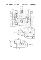
- FIG. 1 is a cross-sectional view of a sheet metal can embodying the invention
- FIG. 2 is a top plan view of end closure structure embodying the invention
- FIG. 3 is a bottom plan view of the embodiment of FIG. 1;
- FIGS. 4, 5 and 6 are schematic, cross-sectional sequential views of cup-shaped work product during fabrication of a one-piece can body embodying the invention
- FIG. 7 is a schematic diagram for describing steps carried out in fabricating work product as shown in FIGS. 4, 5 and 6 and assembling the two-piece can of the invention
- FIG. 8 is a cross-sectional view showing a portion of the tooling and a cup-shaped work product during fabrication of a can body embodying the invention
- FIG. 9 is a cross-sectional view showing a portion of the tooling and the cup-shaped work product, sequential to FIG. 8, upon completing fabrication of the can body of FIG. 6;
- FIG. 10 is a cross-sectional view showing a portion of the tooling and an end closure structure work product during an initial forming operation, in accordance with the invention, in which a recessed end wall panel is formed in a flat-rolled sheet metal blank, flange metal is presented, unitary rivet button formation is initiated and support protrusions in the end wall panel are being formed;
- FIG. 11 is a cross-sectional view of a portion of the tooling and the closure structure work product during an operation subsequent to that of FIG. 12 in which the rivet button is being further shaped and an inwardly directed U-shaped trough is being formed around the periphery of the recessed end wall panel;
- FIG. 12 is a cross-sectional assembly view showing a portion of the tooling and the closure structure work product in an operation subsequent to that of FIG. 11, and prior to attachment of an integral tab opener, in which the sheet metal is being scored within the U-shaped trough of FIG. 11;
- FIG. 13 is a cross-sectional schematic view of a portion of a can body and a portion of a closure structure embodying the invention, shown in juxtaposition for movement into place for forming a chime seam;
- FIG. 14 is a schematic partial view, in cross section, of a can body embodiment capable of assembly with the end closure structure of the invention such that the outer diameter of the chime seam is equal to that of the main body side wall portion.
- the assembled sheet metal can 20 of FIG. 1 utilizes a cup-shaped can body 21 which is free of seams is an important contribution considering the convenience and safety features made available by the invention.
- Portions of this can body such as its unitary end wall and side wall, can be formed by draw-redraw techniques as disclosed in copending U.S. application Ser. No. 712,238, filed Mar. 15, 1985, entitled “Drawn Can Body Methods, Apparatus and Products” (which is included herein by reference).
- a stepped-flange rim 22 (FIG. 6) is formed at its open end.
- Stepped-flange rim 22, side wall 24 and bottom end wall 25 are unitary and each is symmetrically located with respect to central longitudinal axis 26.
- a significant contribution to the food container art is the provision of a convenience-feature opening having a diameter at least equal to that of the side wall main body. This facilitates removal of non-pourable contents (for example semi-solid comestibles) while combining easy-open and edge protection features.
- the main body portion of the side wall is of uniform diameter throughout the height from unitary end wall 25 to stepped-flange rim 22.
- the closure structure 28 of FIG. 2 presents peripheral flange metal 29 which is joined with peripheral flange metal of can body 21 to form a chime seam 30 (FIG. 1); conventional double-seam chime practice can be utilized.
- An elongated tab opener 32 (FIGS. 1 and 2), made integral with closure structure 26, by means such as unitary rivet 33, is oriented diametrically of the cylindrical can; working end 36, longitudinally opposite to handle end 38, is positioned contiguous to a scoreline to be ruptured.
- Methods for fabricating a sheet metal rivet button and securing an opener to a closure structure with a unitary rivet are known in the art so as not to require detailed explanation for purposes of understanding concepts of the present invention.
- the sheet metal of the closure structure is scored in a continuous line.
- Resulting scoreline 40 is located radially inwardly of, but contiguous to, the closure structure flange metal 29 and the resultant can chime seam 30.
- the reduced sheet metal thickness scoreline 40 is strategically positioned for providing the desired opening and, for safety purposes after opening.
- unitary bottom wall 25 is substantially planar (as shown in cross section in FIG. 1) except for nodules such as 44, 45, 46 of FIG. 3.
- nodules extend externally in relation to the cup-shaped can body 21 beyond the transverse plane of the main panel of end wall 25.
- the important function of such nodules is to support a can, on end, in slightly spaced relationship from a heating surface, e.g., when a baby food can is placed, open end up, in a pan of water resting on a burner for purposes of heating the contents of the can.
- Nodules 44, 45, 46 are oriented in a tripod arrangement in FIG. 3 but other arrangements, with additional nodules positioned for stable support, can be utilized.
- cup-shaped configuration, per se, of can body 21 is formed by draw-redraw practice with special stepped-flange tooling and bottom nodule tooling being utilized as final redraw is being completed.
- cup 48 (FIG. 4) having end wall 49, side wall 50 and flange metal 51, at the open end of the cup, extending radially outwardly in transverse relationship to the central longitudinal axis.
- cup 48 has an internal diameter of about 3.5", a side wall height of about 1.27", a radius between end wall 49 and side wall 50 of about 0.2", and a radius between the side wall and flange metal of about 0.04".
- cup 48 is then redrawn into redrawn cup 52, shown in FIG. 5, presenting a decreased diameter end wall 53, increased-height side wall 54 and flange metal 55 at the open end of the redrawn cup.
- Flange metal 55 extends radially outwardly in transverse relationship to the center longitudinal axis of the cup.
- work product 52 has a diameter of about 2.4", a side wall height of about 2.0", a radius between bottom wall 53 and side wall 54 of about 0.07" and a radius between the side wall 54 and flange metal 55 of about 0.04".
- Final can body 21 is formed by redrawing the cup 52 of FIG. 5 to further decrease its diameter, to that shown for end wall 25 and side wall main body 24 (FIG. 1), and to elongate the side wall of cup 52.
- the stepped-flange rim 22 is formed utilizing a portion of the side wall metal and the flange metal of the previous work product cup 52.
- the diameter of wall portion 59 was the diameter of side wall 54 of cup 52 of FIG. 5.
- Ledge 60 which lies in a plane substantially transversely perpendicular to central longitudinal axis 26 and is toroidal in plan view, is formed by interrupting the second redraw before reaching the open end of the can body; the diametric dimension of ledge 60 comprises the reduction in diameter during such final redraw.
- Seam flange metal 62 at the longitudinal end of the can body 21 and at the periphery of rim 22, comprises a portion of flange metal 55 from the work product 52 of FIG. 5, after trimming.
- the final redraw stroke is interrupted so that neither the metal of side wall portion 59, nor flange metal 62, are re-formed during final redraw.
- the diameter of the main body side wall 24 of FIG. 6 has an internal diameter of about 21/8"; the radius between end wall 25 and side wall 24 is about 1/8", the internal diameter of rim side wall portion 59 is about 2.4", the ledge 60 has a radial dimension (one side of the can body) of about 0.17", the radius between side wall 24 and ledge 60 is about 0.03", the radius between wall portion 59 and flange 62 is about 0.07".
- flange metal 62 has been trimmed to be of uniform diameter utilizing commercially available flange trimming apparatus, preferably of the type described in U.S. Pat. No. 4,404,836 of Sept. 20, 1983, entitled "Metal Container Edge Trimming Method and Apparatus".
- continuous strip coated with organic coating on both its surfaces from coil 64 is lubricated as coiled or at lube station 65.
- a circular blank of predetermined diameter is cut from the sheet metal and drawn at cupping and blanking station 66 into the cup-shaped work product with flange metal shown in FIG. 4.
- the cup with flange metal is lubricated on both its surfaces with an FDA-approved lubricant at cup lube station 67 using apparatus as disclosed in copending U.S. application Ser. No. 681,630, filed Dec. 14, 1984, entitled "Electrostatic Lubrication of Cup-Shaped Can Bodies".
- the lubricated cup is then drawn at first redraw station 68 into the work product shown in FIG. 5, relubricated on both surfaces at station 69 and transferred to the final redraw station 70.
- profiling of the closed end wall providing, for example, nodules 44, 45, 46, can be completed utilizing a portion of the stroke of the final redraw apparatus.
- the stepped-flange rim 22 of FIG. 6 can also be formed utilizing such final redraw apparatus as indicated by 72.
- flange metal is trimmed and the can body is inspected at station 75. Filling and closure can be completed at station 76 for delivery of assembled can 20.
- FIG. 8 is a partial view at the final redraw station as the diameter of the work product is being reduced by relative movement between draw die 78, draw ring 79, and draw punch 80 as indicated.
- the sheet metal at 81 is draped across nodule-forming pins, such as 82, which move with draw punch 80.
- the bottom profiling is completed by contact of draw punch 80 with end wall die 84; and, the stepped-flange rim 22 is formed, as shown, by interrupting the redraw before reaching the open end of the can body.
- the side wall portion 59 of the stepped-flange rim 22 comprises, as mentioned, a portion of the side wall of the previous work product; the ledge 60 shown comprises the reduction in diameter of the final redraw, and flange 62 is part of the flange metal from the previous work product.
- Side wall portion 59 and flange metal 62 are not redrawn in the final redraw operation but, rather, the draw die and draw ring 79 are contoured to the desired stepped-flange rim configuration.
- FIGS. 10, 11 and 12 are partial views from shop assembly type drawings showing portions of tooling and work product during forming of a closure structure in accordance with the invention.
- a flat-rolled sheet metal blank of circular configuration and predetermined diameter is cut from sheet or strip material.
- the blank is initially forced, as shown in FIG. 10, to present a generally planar end wall panel 42 recessed longitudinally from peripheral flange 84. Finger indentation 85 is also impressed in end wall panel 42.
- tooling 86 impresses externally directed protrusion 88 as tooling 90 starts formation of a button contour 91 for unitary rivet 33.
- initial contour for a rivet button is progressively shaped in a manner known in the art.
- Rivet button 92 is completed in the step represented by FIG. 11.
- a trough 94 of U-shaped configuration (in radial cross section) is formed about the periphery of end wall panel; such trough extends in the axial direction, protruding on the can interior surface of the closure structure.
- Trough 94 is recessed in relation to the can exterior surface of panel 42 and is located between panel 42 and closure wall portion 95; ledge 96 and wall portion 97 extend to flange metal 84.
- FIG. 12 shows scoring tool 98 forming scoreline 40 in the bottom of trough 94.
- the scoreline 40 is continuous, extending around the length of the trough which circumscribes panel 42.
- Rivet button 92 is ready for the next operation in which an elongated opener is placed over such button and the unitary rivet 33 is formed in accordance with known methods.
- the end closure 26 of FIG. 12 has a diameter of about 2.75" dependent on the length of flange metal 84 with the midpoint of flange metal for chime seam purposes being about 2.6".
- Trough 94 has a depth between about 0.03" to 0.05" (relative to panel 42) and width of 0.1" (in radial cross section).
- Trough wall portion 95 has a height of about 0.085", ledge 96 a radial cross-sectional width of about 0.16", and wall portion 97 a height of about 0.12".
- the centerline of rivet 33 and centerline of protrusion 88 are each about 0.832" along the diameter of closure structure 26 from its center.
- FIG. 13 An enlarged schematic view of a portion of can body 21 along with a similarly enlarged schematic view of a portion of the closure structure 26 are shown in juxtaposition in FIG. 13.
- the stepped-flange of can body 21 presents side wall portion 59, intermediate ledge 60 and flange metal 62.
- Compound curvilinear transition zone 100 extends between ledge 60 and can body side wall 24 and presents a rounded convex edge oriented in the direction of central longitudinal axis 26.
- scoreline 40 When thus assembled, scoreline 40 is contiguous to ledge 60. Trough 94 overlays ledge 60 with scoreline 40 at the radially outward portion (with respect to central axis 26) of the compound curvilinear transition zone 100.
- the severed residual metal edge is shielded by placement of the scoreline 40 in the bottom of U-shaped trough 94.
- the severed residual metal edge (0.002" to about 0.0025" for steel) is not presented as a knife edge but, rather, only as a portion of a significantly thicker edge represented by the depth of trough 94. Only a minor portion of such thickened edge presents a severed metal edge. Protection for such minor edge portion on the throwaway panel pull-out is provided by selection of the depth of trough wall 101.
- the severed residual metal edge which remains affixed to the can body after opening is additionally shielded. That is, in addition to thickened-edge, trough-wall protection, the rounded convex edge of can body 21 at transition zone 100 protects this severed residual metal edge.
- double-reduced flat-rolled steel would be used for manufacture of can bodies for a baby food can. Both surfaces of such flat-rolled steel would include an organic coating.
- the closure structure would typically be made from single-reduced flat-rolled steel.
- Flat-rolled aluminum could be used for the can body, closure, or tab opener.
- Typical sheet metal gages are as follows:
- the can body configuration of FIG. 14 enables an assembled can to roll, on its side, in a straight line.
- the purpose of this is to enable heat treatment of can contents, e.g. baby food, for either cooking or hygienic reasons, in conventional ovens.
- So-called "retorting" ovens convey baby food containers on their sides, which requires them to roll symmetrically about their central longitudinal axis.
- the present invention provides a can body side wall configuration which provides for the chime seam at the open end of the can body to have substantially the same diameter as the main body portion of the can body side wall.
- the present invention avoids use of an abrupt necked-in or lip portion at the open end which would tend to inhibit discharge of contents or make access under such an abrupt necked-in or lip portion difficult.
- a beveled side wall makes a smooth longitudinal transition from the main body side wall portion toward the open end of the can body.
- a beveled side wall one-piece can body 104 is symmetrical about central longitudinal axis 105.
- Closed end wall 106 is unitary with cylindrical configuration main body side wall portion 107 and beveled side wall portion 108 which extends longitudinally toward the open end of the can body.
- Stepped-flange rim 109 extends from a reduced-diameter cylindrical wall portion 110 and includes ledge 111, rim wall portion 112 and peripheral flange metal 114. Stepped-flange rim 109 serves the corresponding purposes, for adding an end closure structure and protecting severed scoreline metal, as described in relation to stepped-flange 22 of earlier figures. However, in forming a chime seam with can body flange metal 114 and flange metal 84 of closure 26, the outer diameter of the chime seam thus formed is substantially equal to the outer diameter of main body side wall portion 107.
- the beveled side wall 108 of FIG. 14 is preferably fabricated by selecting tooling conforming to the desired configuration of side wall 108 and use of eccentrically-mounted side wall rolling apparatus of the type available from the Carnation Company, 5045 Wilshire Blvd., Los Angeles, Calif. 90036, or from Metal Box Engineering, Queens House, Forbury Road, Reading RG1 3JH, Great Britain; more conventionally, such apparatus is used for rolling reinforcing ribs into tubular side walls of sheet metal cans.
- the final can body is redrawn to the diameter of main body side wall portion 107 with extra length flange metal oriented transversely to the central axis of the cylindrical side wall; such added length flange metal provides for pulling-in of flange metal into the side wall during eccentric rolling of the side wall.
- Beveled side wall portion 108 is eccentrically rolled into the cylindrical wall portion above main body portion 107 starting at the juncture 115 between such wall portions and working toward such open end. After eccentric rolling of beveled side wall portion 108, stepped-flange rim 109 is formed, above reduced-diameter wall portion 110, from reduced-diameter side wall and flange metal at the open end of the can body.
- Such wall heights do not include dimensions of compound curvilinear transition zones between horizontal and vertical portions of the can body; such radius dimensions are tabulated below:
- FIG. 14 could also be formed by removing flange metal after a draw-redraw process, by progressively necking-in the side wall above 115 to the reduced diameter of side wall portion 110, then forming the stepped-flange rim in necked-in metal remaining above the reduced-diameter wall 110.
Landscapes
- Engineering & Computer Science (AREA)
- Mechanical Engineering (AREA)
- Closures For Containers (AREA)
- Rigid Containers With Two Or More Constituent Elements (AREA)
Abstract
Description
______________________________________
Part            Steel     Aluminum
______________________________________
can body        .005-.009"
                          .007-.012"
closure structure
                .007-.009"
                          .008-.011"
tab opener      .011-.015"
                          .014-.020"
______________________________________
______________________________________
                Diameter
                       Height
______________________________________
Main body side wall 107
                  1.625"   .675"
Beveled side wall 108
                  1.25"    1.0"
(at reduced-diameter
110)
Wall portion 110  1.25"    0.15"
Rim wall 112      1.52"    .083"
______________________________________
______________________________________ Transition Zone Approximate between Radius ______________________________________flange 114 andwall 112 .06"wall 112 and ledge 111 .07" ledge 111 andwall 110 .03"wall 110 andwall 108 .09"wall 108 andwall 107 .10"wall 107 andbottom 106 .20" Ledge 111 has a radial dimension of about .27". ______________________________________
Claims (9)
Priority Applications (1)
| Application Number | Priority Date | Filing Date | Title |
|---|---|---|---|
| US06/854,914 US4669629A (en) | 1986-04-23 | 1986-04-23 | Full-open convenience-feature sheet metal can |
Applications Claiming Priority (1)
| Application Number | Priority Date | Filing Date | Title |
|---|---|---|---|
| US06/854,914 US4669629A (en) | 1986-04-23 | 1986-04-23 | Full-open convenience-feature sheet metal can |
Publications (1)
| Publication Number | Publication Date |
|---|---|
| US4669629A true US4669629A (en) | 1987-06-02 |
Family
ID=25319853
Family Applications (1)
| Application Number | Title | Priority Date | Filing Date |
|---|---|---|---|
| US06/854,914 Expired - Lifetime US4669629A (en) | 1986-04-23 | 1986-04-23 | Full-open convenience-feature sheet metal can |
Country Status (1)
| Country | Link |
|---|---|
| US (1) | US4669629A (en) |
Cited By (6)
| Publication number | Priority date | Publication date | Assignee | Title |
|---|---|---|---|---|
| US5169017A (en) * | 1990-09-05 | 1992-12-08 | H. J. Heinz Company | Can end closure apparatus |
| USD428543S (en) * | 1999-07-07 | 2000-07-18 | Robin Dawn Schwab | Container |
| WO2006110818A3 (en) * | 2005-04-11 | 2007-11-08 | Willett M S Inc | Can bodies |
| US20080017640A1 (en) * | 2006-07-20 | 2008-01-24 | Crown Packaging Technology Inc. | Can end having curved end panel surfaces |
| US20150052852A1 (en) * | 2012-04-17 | 2015-02-26 | Krones Ag | Method and device for can manufacture and canning |
| WO2025085409A1 (en) * | 2023-10-16 | 2025-04-24 | Novelis Inc. | Can end with panel features for buckling resistance |
Citations (2)
| Publication number | Priority date | Publication date | Assignee | Title |
|---|---|---|---|---|
| US3251502A (en) * | 1963-12-17 | 1966-05-17 | Continental Can Co | Safe opening can |
| US3762596A (en) * | 1970-07-24 | 1973-10-02 | Dorn Co V | Easy opening can end |
-
1986
- 1986-04-23 US US06/854,914 patent/US4669629A/en not_active Expired - Lifetime
Patent Citations (2)
| Publication number | Priority date | Publication date | Assignee | Title |
|---|---|---|---|---|
| US3251502A (en) * | 1963-12-17 | 1966-05-17 | Continental Can Co | Safe opening can |
| US3762596A (en) * | 1970-07-24 | 1973-10-02 | Dorn Co V | Easy opening can end |
Cited By (7)
| Publication number | Priority date | Publication date | Assignee | Title |
|---|---|---|---|---|
| US5169017A (en) * | 1990-09-05 | 1992-12-08 | H. J. Heinz Company | Can end closure apparatus |
| USD428543S (en) * | 1999-07-07 | 2000-07-18 | Robin Dawn Schwab | Container |
| WO2006110818A3 (en) * | 2005-04-11 | 2007-11-08 | Willett M S Inc | Can bodies |
| US20080017640A1 (en) * | 2006-07-20 | 2008-01-24 | Crown Packaging Technology Inc. | Can end having curved end panel surfaces |
| US8191726B2 (en) * | 2006-07-20 | 2012-06-05 | Crown Packaging Technology, Inc. | Can end having curved end panel surfaces |
| US20150052852A1 (en) * | 2012-04-17 | 2015-02-26 | Krones Ag | Method and device for can manufacture and canning |
| WO2025085409A1 (en) * | 2023-10-16 | 2025-04-24 | Novelis Inc. | Can end with panel features for buckling resistance |
Similar Documents
| Publication | Publication Date | Title |
|---|---|---|
| US4102467A (en) | Tapered plastic container with seamed metal end and method for making it | |
| US3995572A (en) | Forming small diameter opening for aerosol, screw cap, or crown cap by multistage necking-in of drawn or drawn and ironed container body | |
| US5014536A (en) | Method and apparatus for drawing sheet metal can stock | |
| US3964413A (en) | Methods for necking-in sheet metal can bodies | |
| US3705563A (en) | Method of forming convenience closure for container body | |
| US4503702A (en) | Tapered container and method and apparatus for forming same | |
| US4768672A (en) | Container profile with stacking feature | |
| US3998174A (en) | Light-weight, high-strength, drawn and ironed, flat rolled steel container body method of manufacture | |
| US4263800A (en) | Method of forming a nestable container | |
| US4366696A (en) | Nestable can method of manufacture | |
| US4584859A (en) | In-line control during draw-redraw of one-piece sheet metal can bodies | |
| US4264017A (en) | Container shape | |
| US10947002B2 (en) | Reverse pressure can end | |
| EP3676029B1 (en) | Pressure can end compatible with standard can seamer and method of forming the same | |
| US7185525B2 (en) | Method and container having reinforcing rib structures | |
| US4184444A (en) | Tapered plastic container with seamed metal end and method for making it | |
| US4669629A (en) | Full-open convenience-feature sheet metal can | |
| EP0372687A1 (en) | Manufacture of can bodies | |
| US4054227A (en) | Selective coating characteristic tinplated steel cans | |
| EP0599583B1 (en) | Method of making a container body and a closure for the body | |
| US3630408A (en) | Protective bead for a container opening | |
| US3608774A (en) | Drawn can for accommodating conventional openers | |
| EP0512984B1 (en) | Method and apparatus for processing containers | |
| US10518926B2 (en) | Reverse pressure can end | |
| US5263354A (en) | Drawn can body methods, apparatus and products |
Legal Events
| Date | Code | Title | Description |
|---|---|---|---|
| AS | Assignment |
Owner name: WEIRTON STEEL CORPORATION, THREE SPRINGS DRIVE, WE Free format text: ASSIGNMENT OF ASSIGNORS INTEREST.;ASSIGNOR:SAUNDERS, WILLIAM T.;REEL/FRAME:004568/0344 Effective date: 19860417 |
|
| STCF | Information on status: patent grant |
Free format text: PATENTED CASE |
|
| CC | Certificate of correction | ||
| FPAY | Fee payment |
Year of fee payment: 4 |
|
| FPAY | Fee payment |
Year of fee payment: 8 |
|
| FPAY | Fee payment |
Year of fee payment: 12 |
|
| AS | Assignment |
Owner name: ISG WEIRTON INC., OHIO Free format text: NUNC PRO TUNC ASSIGNMENT;ASSIGNOR:WEIRTON STEEL CORPORATION;REEL/FRAME:014743/0420 Effective date: 20040422 |
|
| AS | Assignment |
Owner name: ISG TECHNOLOGIES INC., PENNSYLVANIA Free format text: NUNC PRO TUNC ASSIGNMENT;ASSIGNOR:ISG WEIRTON INC.;REEL/FRAME:014805/0948 Effective date: 20040628 |