US466722A - Grain-harvester - Google Patents
Grain-harvester Download PDFInfo
- Publication number
- US466722A US466722A US466722DA US466722A US 466722 A US466722 A US 466722A US 466722D A US466722D A US 466722DA US 466722 A US466722 A US 466722A
- Authority
- US
- United States
- Prior art keywords
- apron
- grain
- elevator
- wheel
- deck
- Prior art date
- Legal status (The legal status is an assumption and is not a legal conclusion. Google has not performed a legal analysis and makes no representation as to the accuracy of the status listed.)
- Expired - Lifetime
Links
- 239000000969 carrier Substances 0.000 description 6
- 230000009471 action Effects 0.000 description 4
- XEEYBQQBJWHFJM-UHFFFAOYSA-N Iron Chemical compound [Fe] XEEYBQQBJWHFJM-UHFFFAOYSA-N 0.000 description 2
- 230000008901 benefit Effects 0.000 description 2
- 238000010276 construction Methods 0.000 description 2
- 240000001973 Ficus microcarpa Species 0.000 description 1
- 229910052742 iron Inorganic materials 0.000 description 1
- 230000007246 mechanism Effects 0.000 description 1
- 239000002184 metal Substances 0.000 description 1
- 229910052751 metal Inorganic materials 0.000 description 1
- 238000000034 method Methods 0.000 description 1
- 230000008569 process Effects 0.000 description 1
Images

Classifications
-
- A—HUMAN NECESSITIES
- A01—AGRICULTURE; FORESTRY; ANIMAL HUSBANDRY; HUNTING; TRAPPING; FISHING
- A01D—HARVESTING; MOWING
- A01D43/00—Mowers combined with apparatus performing additional operations while mowing
- A01D43/06—Mowers combined with apparatus performing additional operations while mowing with means for collecting, gathering or loading mown material
Definitions
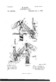
- Figure l is a front elevation showing a portion of a frame of a harvester embodying my invention, the elevator and a portion of the platform conveyer being shown, but stripped of mechanism, except such as relates to the invention in question.
- Fig. 2 is a rear elevation of the same structure shown in Fig. l.
- Fig. 3 is a vertical section at the line 3 3 on Fig. 2.
- Fig. 4 is a vertical section at the line 4 4 on Fig. 3.
- A is the drive-wheel.
- B is the front sill, and C the rear sill, of the main frame.
- D is the finger-bar, and E the rear sill, of the conveyer-platform, which are rigid with the main-frame sills.
- F is an outer side oblique post at the forward end, and G a corresponding post at the rear end, which are secured, respectively, to the front and rear sills B and C, projecting upward therefrom parallel to each other, leaning grainward.
- .I and K are respectively the front and rear elevator sides, which may be of metal plate. They are secured parallel to each other edgewise, their upper ends being fastened, respectively, to the leaning posts F and G and their lower ends to the upright posts II and I. Suitable special means may be employed to render them securely rigid with said posts, ⁇
- the curved iron bars L'L are secured to the leaning posts F and G, respectively, and to said curved bars, as well as to said posts, the elevator' sides are bolted.
- the main driving-shaft through which power may be communicated from the drivewheel in any convenient manner. (Not shown.) It has its most grainward bearing in the journal-box b at the forward side of the sill B, at the grainward end thereof.
- the beveled gear-wheel B2 is made fast and Ineshes with and drives the beveled pinion H', which is fixed on the forward end of the horizontal shaft 7L.
- Said shaft has bearings provided for it on the upright posts H and I at the front and rear ends, respectively, of the machine, and between said bearings it carries rigid with it the lower or driving roller H2 of the upper elevator-apron M.
- the posts H and I support bearings near their lower'ends for the horizontal shaft o, which carries the platform conveyer driving-roller O and has rigid with it, rearward of its rear bearing, thesprocket-wheel 0"'.
- the shaft o is in substantially the same vertical plane as the shaft 7L', being therefore directly underneath it.
- n is the shaft of the lower or driving roller N of the lower elevator-apron N. It is located rearward of the vertical plane of the shaft 71, and a little higher than the horizontal plane of the shaft o and has bearings at its front and rear ends, which may be conveniently obtained on the front and rear platform sills or main-frame sills, respectively. Rearward of its rear bearing it has secured rigidly to it the sprocket-wheel N2.
- the lever Q is a lever pivoted at q on the horizontal frame-bar G', which extends from the rear post G horizontally grainward to the upper end of the post I, to which it is secured.
- the sprocket-wheel At the grainward end of the lever Q, on a studaxle, there is journaled the sprocket-wheel
- the stubbleward end of the lever Q has the slotted segment-arm Q3, whose slot is in the arc of a circle about the pivot q, and a clamping-bolt Q4 passes through 4said slot into the frame-bar Q', and, being tightened, will hold the lever rigid with the bar, the slot permitting the adjustment of the lever about its IOO pivot to vary the vertical position of the sprocket-wheel Q2.
- All the sprocket-wheels M O ,N2, and Q2 arein the same vertical plane, and the drive-chain Pengages all of them, passing partly around the wheels O', N2, and Q3 in the same direction, having said wheels within its path, while the wheel M is outside the chain and engaged thereby in a manner to drive it in the reverse direction from the other wheels. served, serves as a tightener for the chain l.
- the upper or idle roller .N3 of the lower elevator-apron N is located grainward of the vertical plane of the drive-wheel and may be below the level of the top of the wheel. Its bearings are obtained in journal-boxes on the bars L L.
- the upper or idle roller M3 of the upper elevator-apron is located above the drive-wheel, being therefore considerably farther stubbleward as well as considerably higher than the roller N3 ofthe lower apron.
- S is a curved deck, convex upward, which overhangs the drive-wheel and is overhung by the roller M3. Its grainward edge is in ⁇ close proximity to the delivery side or 'end of the lower elevator-apron, and the most effective position for it is substantially in the oblique plane of the axesy of the lower elevatorroller, so that the grain delivered olf the upper end of that apron is lodged on said deck S at its grainward edge.
- the curved form of this deck is not essential, but is the proper form, or the form that it Vnaturally assumes when the elevator-roller N3 is located lower.
- the stubbleward edge of the deck S makes an angle with or overhangs the binder-deck T. It constitutes, therefore, a bridge from the lower elevator-apron to the binder-deck, spanning ⁇ the horizontal interval between the two, in which interval the drive-wheel is located.
- the position of the upper or idle roller M3 relatively to the lower or driving roller H2 of the upper elevator-apron and relatively to the idle-roller N3 of the lower apron is such that the ⁇ upper apron stretched between the lower sides of its rollers-that is to say, the lower ply of the upper apron-when taut, nearly contacts the lower apron where it passes over the roller N3, leaving a very narrow mouth or rift at that point, so that the grain which may be introduced between the two aprons will force its own way by forcing the lower ply of the upper apron upward away from the lower apron as it passes over the roller M3 at the upper side of said lower apron.
- the shaft of the lower or driving'roller of' the upper apron directly overhangs the shafty of the driving -roller of the platformconveyer apron.
- the said elevator The wheel Q3 it will be ob driving-roller H2 is larger than the platformconveyer driving-roller, so that the upper elevator-apron considerably overhangs the stub- ⁇ bleward end of the platform-conveyer, which adapts said apron to assist in clearing the grain olf the platform conveyer and starting it upward and tends to make it possible to dispense with any other clearing device at the end of the platform conveyer; but the extension of this elevator-apron so far grainward as necessaryin order to bring its receiving end into the relation stated to the platform-conveyer, especially in view of the fact that said elevatorroller is driven from its forward end, necessi- -tates a shield and grain-defiectorR to cover the gearing at the forward end of
- this elevator will be understood by those familiar with the art to be designed to be such that the grain will be taken from the platform conveyer .by the direct action of the upper elevator-apron at its lower receiving end, where it passes around the driving-roller, and will be delivered upon and received by the lower elevator-apron, and thence carried between the two aprons bodily to the upper or discharge side of the lower apron, from which it will be delivered onto the bridge or deck S. If the quantity delivered is not sufficient to experience pressure from the upper apron after it has lodged on the said bridge S, it will accumulate on said IOO IOS
- Another advantage of this structure is that it reduces very materially the height of the machine as compared with the usual elevating-machines, which carry the grain up over the drive-wheel and bind it on the outer side.
- Another advantage is that it makes it possible to narrow the machine up and bring the drive-Wheel nearer to the end of the platform conveyer without increasing the pitchof the elevator, this gain being due to the fact that, while the platform conveyer has its discharge side in the usual relation to the stubbleward line of the cut, the elevator overhangs the conveyer and commences its work therefore several inches farther grainward than is customary, and, further, that intervening devices for clearing the grain' from the platform-conveyer are dispensed with.
- the platform conveyer, the drive-wheel, and binder-deck 1ocated at the stubbleward side of the drivewheel combined with an elevator composed of two inclined endless carriers, one overhanging the other, the lower of such inclined carriers having its receiving side at the discharge side of the platform conveyer and its discharge side at the grainward side of the vertical plane of the drive-wheel, and a stationary bridge or deck extending over the drive-wheel from the discharge side of the lower carrier to the receiving side of the binder-deck, the upper of said endless ele-h vator-carriers having its receiving side overhanging the platform conveyer and its delivery side overhanging said bridge or deck above the drive-Wheel, substantially as set forth.
Landscapes
- Life Sciences & Earth Sciences (AREA)
- Environmental Sciences (AREA)
- Lift-Guide Devices, And Elevator Ropes And Cables (AREA)
Description
(No Model.)
2 Sheets-Sheet 2. M. KANE.
GRAIN HARVESTER.
UNITED STATES MAURICE KANE, OF CHICAGO, ILLINOIS, ASSIGNOR TO PATENT OFFICE.
TIIE \VARDER, BUSH- GRAIN-HARVESTER.
SPECIFICATION forming part of Letters Patent N o. 466,722, dated January 5, 1892.. Application filed June 8, 1891- Sen'al No. 395,571. (No model.)
To a/ZZ whom t may concern: Y
Be it known that I, MAURICE KANE, a citizen of the United States, residing at Chicago, county of Cook, and `State of Illinois, have in- Vented certain new and useful Improvements in Grain-Harvesters, which are fully set forth in the following specification, reference being had to the accompanying drawings, forming a part thereof.
In the drawings, Figure l is a front elevation showing a portion of a frame of a harvester embodying my invention, the elevator and a portion of the platform conveyer being shown, but stripped of mechanism, except such as relates to the invention in question. Fig. 2 is a rear elevation of the same structure shown in Fig. l. Fig. 3 is a vertical section at the line 3 3 on Fig. 2. Fig. 4 is a vertical section at the line 4 4 on Fig. 3.
A is the drive-wheel.
B is the front sill, and C the rear sill, of the main frame.
D is the finger-bar, and E the rear sill, of the conveyer-platform, which are rigid with the main-frame sills.
F is an outer side oblique post at the forward end, and G a corresponding post at the rear end, which are secured, respectively, to the front and rear sills B and C, projecting upward therefrom parallel to each other, leaning grainward.
II and I are upright posts secured to the front and rear sills B and C, respectively, at their grainward ends-that is, at the stubbleward end of the platform conveyer.
.I and K are respectively the front and rear elevator sides, which may be of metal plate. They are secured parallel to each other edgewise, their upper ends being fastened, respectively, to the leaning posts F and G and their lower ends to the upright posts II and I. Suitable special means may be employed to render them securely rigid with said posts,`
and for this purpose, iny addition to the further purpose of furnishing support for the bearing of one of the elevator-rollers, as hereinafter explained, the curved iron bars L'L are secured to the leaning posts F and G, respectively, and to said curved bars, as well as to said posts, the elevator' sides are bolted.
B is the main driving-shaft, through which power may be communicated from the drivewheel in any convenient manner. (Not shown.) It has its most grainward bearing in the journal-box b at the forward side of the sill B, at the grainward end thereof. On
` the end of the shaft B', grainward from said bearing Z), the beveled gear-wheel B2 is made fast and Ineshes with and drives the beveled pinion H', which is fixed on the forward end of the horizontal shaft 7L. Said shaft has bearings provided for it on the upright posts H and I at the front and rear ends, respectively, of the machine, and between said bearings it carries rigid with it the lower or driving roller H2 of the upper elevator-apron M. On the rear end of the shaft h', rearward of the rear bearing of said shaft, there is made fast the sprocket-wheel M. The posts H and I support bearings near their lower'ends for the horizontal shaft o, which carries the platform conveyer driving-roller O and has rigid with it, rearward of its rear bearing, thesprocket-wheel 0"'. The shaft o is in substantially the same vertical plane as the shaft 7L', being therefore directly underneath it.
n is the shaft of the lower or driving roller N of the lower elevator-apron N. It is located rearward of the vertical plane of the shaft 71, and a little higher than the horizontal plane of the shaft o and has bearings at its front and rear ends, which may be conveniently obtained on the front and rear platform sills or main-frame sills, respectively. Rearward of its rear bearing it has secured rigidly to it the sprocket-wheel N2.
Q is a lever pivoted at q on the horizontal frame-bar G', which extends from the rear post G horizontally grainward to the upper end of the post I, to which it is secured. At the grainward end of the lever Q, on a studaxle, there is journaled the sprocket-wheel The stubbleward end of the lever Q has the slotted segment-arm Q3, whose slot is in the arc of a circle about the pivot q, and a clamping-bolt Q4 passes through 4said slot into the frame-bar Q', and, being tightened, will hold the lever rigid with the bar, the slot permitting the adjustment of the lever about its IOO pivot to vary the vertical position of the sprocket-wheel Q2. All the sprocket-wheels M O ,N2, and Q2 arein the same vertical plane, and the drive-chain Pengages all of them, passing partly around the wheels O', N2, and Q3 in the same direction, having said wheels within its path, while the wheel M is outside the chain and engaged thereby in a manner to drive it in the reverse direction from the other wheels. served, serves as a tightener for the chain l. The upper or idle roller .N3 of the lower elevator-apron N is located grainward of the vertical plane of the drive-wheel and may be below the level of the top of the wheel. Its bearings are obtained in journal-boxes on the bars L L. The upper or idle roller M3 of the upper elevator-apron is located above the drive-wheel, being therefore considerably farther stubbleward as well as considerably higher than the roller N3 ofthe lower apron.
Brackets m3 m3, secured to the leaning posts F and G, respectively, afford the bearings for the shaft of the roller M3.
S is a curved deck, convex upward, which overhangs the drive-wheel and is overhung by the roller M3. Its grainward edge is in` close proximity to the delivery side or 'end of the lower elevator-apron, and the most effective position for it is substantially in the oblique plane of the axesy of the lower elevatorroller, so that the grain delivered olf the upper end of that apron is lodged on said deck S at its grainward edge. The curved form of this deck is not essential, but is the proper form, or the form that it Vnaturally assumes when the elevator-roller N3 is located lower.
than the top of the wheel or lower than any portion of the machine which stands above thel wheel and over which grain must be moved to reach the binder-deck. The stubbleward edge of the deck S makes an angle with or overhangs the binder-deck T. It constitutes, therefore, a bridge from the lower elevator-apron to the binder-deck, spanning` the horizontal interval between the two, in which interval the drive-wheel is located. The position of the upper or idle roller M3 relatively to the lower or driving roller H2 of the upper elevator-apron and relatively to the idle-roller N3 of the lower apron is such that the `upper apron stretched between the lower sides of its rollers-that is to say, the lower ply of the upper apron-when taut, nearly contacts the lower apron where it passes over the roller N3, leaving a very narrow mouth or rift at that point, so that the grain which may be introduced between the two aprons will force its own way by forcing the lower ply of the upper apron upward away from the lower apron as it passes over the roller M3 at the upper side of said lower apron. As stated above, the shaft of the lower or driving'roller of' the upper apron directly overhangs the shafty of the driving -roller of the platformconveyer apron. It will be observed, also, from the drawings that the said elevator The wheel Q3, it will be ob driving-roller H2 is larger than the platformconveyer driving-roller, so that the upper elevator-apron considerably overhangs the stub- `bleward end of the platform-conveyer, which adapts said apron to assist in clearing the grain olf the platform conveyer and starting it upward and tends to make it possible to dispense with any other clearing device at the end of the platform conveyer; but the extension of this elevator-apron so far grainward as necessaryin order to bring its receiving end into the relation stated to the platform-conveyer, especially in view of the fact that said elevatorroller is driven from its forward end, necessi- -tates a shield and grain-defiectorR to cover the gearing at the forward end of the roller H3, and especially to project forward therefrom obliquely stubbleward to act as a gatherer, and, in co-operation with the ordinary stubbleward gatherer V, which is located directly below it, to gather the grain toward the sickle and prevent it from being forced down or becoming engaged with the gearing or becoming an obstruction at the heel .of the sickle.v By this construction it will be seen that the upper elevator-apron is made to extend grainward past the line of the standing grain, and therefore past the stubbleward end of the line of the sickles cutting action.
The operation of this elevator will be understood by those familiar with the art to be designed to be such that the grain will be taken from the platform conveyer .by the direct action of the upper elevator-apron at its lower receiving end, where it passes around the driving-roller, and will be delivered upon and received by the lower elevator-apron, and thence carried between the two aprons bodily to the upper or discharge side of the lower apron, from which it will be delivered onto the bridge or deck S. If the quantity delivered is not sufficient to experience pressure from the upper apron after it has lodged on the said bridge S, it will accumulate on said IOO IOS
IIO
bridge until a sufficient quantity has been so delivered to cause the action of the upper apron or the pressure of the grain still accumulating from the elevator to move it. over the bridge S stubbleward and cause it to discharge onto the binder-deck. If the grain is scanty, the temporary halting which will occur on the bridge S affords opportunity for the grain to be straightened if it is delivered in oblique position, and the action of the upper apron overhanging the grain thus. being lod ged upon the bridge will greatly assist this straightening process, so that the grain ultimately delivered to the binder-deck is likely to reach it in much better condition for binding than if it had been carried between the two elevator-aprons all the wayand discharged from between them directly onto the binderdeck; and this is one purpose of the invention; and when, as illustrated, the stubbleward side of the bridge S overhangs or makes a decided angle with the binder-deck, so that the grain descending from the bridge is arrested by the deck, a further tendency to become straightened is experienced by the grain, and this result also is contemplated in my invention. Another advantage of this structure is that it reduces very materially the height of the machine as compared with the usual elevating-machines, which carry the grain up over the drive-wheel and bind it on the outer side. Another advantage is that it makes it possible to narrow the machine up and bring the drive-Wheel nearer to the end of the platform conveyer without increasing the pitchof the elevator, this gain being due to the fact that, while the platform conveyer has its discharge side in the usual relation to the stubbleward line of the cut, the elevator overhangs the conveyer and commences its work therefore several inches farther grainward than is customary, and, further, that intervening devices for clearing the grain' from the platform-conveyer are dispensed with.
The hereinabove-described features of construction relating to the shield R and its relation to the elevator and platform-conveyer I do not claim in this specification, because they .are included in my application,- Serial No. 406,304, filed September 21, 1891, as a division hereof.
I claim- 1. In a grain-harvester, a platform conveyl er, the drive-Wheel, and the binder-deck located at the stubbleward side of the drivewheel, combined with an elevator composed of two inclined endless carriers, one overhanging the other, the lower of said inclined carriers having its discharge side at the grainward side of the vertical plane of the drivewheel, and a stationary deck or bridge eX- tending over the Wheel from the discharge side of said lower carrier to the receiving side of the binder-deck, the upper of said elevator endless carriers overhanging said bridge or deck, substantially as set forth.
2. In a grain-harvester, the platform conveyer, the drive-wheel, and binder-deck 1ocated at the stubbleward side of the drivewheel, combined with an elevator composed of two inclined endless carriers, one overhanging the other, the lower of such inclined carriers having its receiving side at the discharge side of the platform conveyer and its discharge side at the grainward side of the vertical plane of the drive-wheel, and a stationary bridge or deck extending over the drive-wheel from the discharge side of the lower carrier to the receiving side of the binder-deck, the upper of said endless ele-h vator-carriers having its receiving side overhanging the platform conveyer and its delivery side overhanging said bridge or deck above the drive-Wheel, substantially as set forth. In testimony whereof I have hereunto set my hand, at Chicago, Illinois, this 26th day of May, 1891.
MAURICE KANE.
XVitnesses:
JEAN ELLIOTT, JULIA UsLER.
Publications (1)
| Publication Number | Publication Date |
|---|---|
| US466722A true US466722A (en) | 1892-01-05 |
Family
ID=2535586
Family Applications (1)
| Application Number | Title | Priority Date | Filing Date |
|---|---|---|---|
| US466722D Expired - Lifetime US466722A (en) | Grain-harvester |
Country Status (1)
| Country | Link |
|---|---|
| US (1) | US466722A (en) |
-
0
- US US466722D patent/US466722A/en not_active Expired - Lifetime
Similar Documents
| Publication | Publication Date | Title |
|---|---|---|
| US656690A (en) | Harvesting-machine. | |
| US779994A (en) | Cutting apparatus for mowers, reapers, &c. | |
| US393774A (en) | Divider for harvesting-machines | |
| US360061A (en) | Xgrain-harvester | |
| US1036467A (en) | Harvesting-machine. | |
| US311997A (en) | Grain-binding harvester | |
| US575134A (en) | Combined harvester and thresher | |
| US359828A (en) | Corn-harvester | |
| US283097A (en) | Machine | |
| US753883A (en) | Swather attachment for mowing-machines. | |
| US329931A (en) | Grain-binding harvester | |
| US973421A (en) | Mower attachment. | |
| US434494A (en) | Harvester | |
| US251334A (en) | Peters | |
| US349932A (en) | Eichaed emerson | |
| US581660A (en) | Corn harvesting and b | |
| US150992A (en) | Improvement in harvesters | |
| US493530A (en) | Self-binding harvester | |
| US725943A (en) | Harvesting-machine. | |
| US307374A (en) | blood | |
| US1161252A (en) | Ensilage-harvester. | |
| US401388A (en) | Corn-harvesting machine | |
| US377077A (en) | kennedy | |
| US324772A (en) | jenkins | |
| US211730A (en) | Improvement in harvester-droppers |