US466105A - Ernst rockiiatjsen - Google Patents
Ernst rockiiatjsen Download PDFInfo
- Publication number
- US466105A US466105A US466105DA US466105A US 466105 A US466105 A US 466105A US 466105D A US466105D A US 466105DA US 466105 A US466105 A US 466105A
- Authority
- US
- United States
- Prior art keywords
- metal
- draw
- plate
- bead
- moldings
- Prior art date
- Legal status (The legal status is an assumption and is not a legal conclusion. Google has not performed a legal analysis and makes no representation as to the accuracy of the status listed.)
- Expired - Lifetime
Links
- 239000002184 metal Substances 0.000 description 19
- 229910052751 metal Inorganic materials 0.000 description 19
- 239000011324 bead Substances 0.000 description 17
- 238000000465 moulding Methods 0.000 description 12
- 238000000034 method Methods 0.000 description 9
- 239000002023 wood Substances 0.000 description 3
- PXHVJJICTQNCMI-UHFFFAOYSA-N Nickel Chemical compound [Ni] PXHVJJICTQNCMI-UHFFFAOYSA-N 0.000 description 2
- 229910001369 Brass Inorganic materials 0.000 description 1
- RYGMFSIKBFXOCR-UHFFFAOYSA-N Copper Chemical compound [Cu] RYGMFSIKBFXOCR-UHFFFAOYSA-N 0.000 description 1
- 239000010951 brass Substances 0.000 description 1
- 229910052802 copper Inorganic materials 0.000 description 1
- 239000010949 copper Substances 0.000 description 1
- 229910052759 nickel Inorganic materials 0.000 description 1
Images
Classifications
-
- B—PERFORMING OPERATIONS; TRANSPORTING
- B21—MECHANICAL METAL-WORKING WITHOUT ESSENTIALLY REMOVING MATERIAL; PUNCHING METAL
- B21D—WORKING OR PROCESSING OF SHEET METAL OR METAL TUBES, RODS OR PROFILES WITHOUT ESSENTIALLY REMOVING MATERIAL; PUNCHING METAL
- B21D39/00—Application of procedures in order to connect objects or parts, e.g. coating with sheet metal otherwise than by plating; Tube expanders
- B21D39/03—Application of procedures in order to connect objects or parts, e.g. coating with sheet metal otherwise than by plating; Tube expanders of sheet metal otherwise than by folding
-
- Y—GENERAL TAGGING OF NEW TECHNOLOGICAL DEVELOPMENTS; GENERAL TAGGING OF CROSS-SECTIONAL TECHNOLOGIES SPANNING OVER SEVERAL SECTIONS OF THE IPC; TECHNICAL SUBJECTS COVERED BY FORMER USPC CROSS-REFERENCE ART COLLECTIONS [XRACs] AND DIGESTS
- Y10—TECHNICAL SUBJECTS COVERED BY FORMER USPC
- Y10T—TECHNICAL SUBJECTS COVERED BY FORMER US CLASSIFICATION
- Y10T29/00—Metal working
- Y10T29/49—Method of mechanical manufacture
- Y10T29/49826—Assembling or joining
- Y10T29/49908—Joining by deforming
-
- Y—GENERAL TAGGING OF NEW TECHNOLOGICAL DEVELOPMENTS; GENERAL TAGGING OF CROSS-SECTIONAL TECHNOLOGIES SPANNING OVER SEVERAL SECTIONS OF THE IPC; TECHNICAL SUBJECTS COVERED BY FORMER USPC CROSS-REFERENCE ART COLLECTIONS [XRACs] AND DIGESTS
- Y10—TECHNICAL SUBJECTS COVERED BY FORMER USPC
- Y10T—TECHNICAL SUBJECTS COVERED BY FORMER US CLASSIFICATION
- Y10T29/00—Metal working
- Y10T29/53—Means to assemble or disassemble
- Y10T29/53709—Overedge assembling means
- Y10T29/53787—Binding or covering
Definitions
- the object of this invention is to produce ornamental borders for picture-frames, cornices, and the like, with moldings, beads, and other projecting parts covered with metal.
- Borders produced by my method offer the advantage of being stronger than other similar articles hitherto produced by partly gilding over wooden borders.
- Sheet metal whether plain, embossed, or perforated, the use of which isinvolved in this method, enables very tasteful articles to be obtained and the ornamental effect to be extensively varied. It will of course depend on the color of the wood whether nickel, brass, copper, or other metal is employed.
- the method consistsin causing the borders, together with the sheet metal applied to them, to pass through draw-plates corresponding in contour to the borde'rs-t. e.,
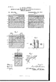
- Figures 1 to 3 are sections of a border or piece of molding in the act of being passed through the draw-plates and representing it in three difierent stages of the method.
- Figures 1 to 3 are sections of a border or piece of molding in the act of being passed through the draw-plates and representing it in three difierent stages of the method.
- Fig. 4 is a plan of the lower part of the draw-plate.
- Fig. 5 is a longitudinal section of the drawplate, and Fig. 6 is a section on an enlarged scale of a finished border or piece of molding.
- the draw-plates a a used for this purpose present exactly'the shape of the border in question, save as regards the grooves 19 1) into which enter the beads or moldings 0c of the border.
- These grooves at the entrance y, Figs. 4. and 5, of the draw-plates have flat surfaces, and are of the same width as the strips of sheet metal a .2, which are to cover the beads 00 0:,Fig. 1.
- the grooves gradually merge from a fiat to a curved shape (an intermediate degree is shown in Fig. 2) until it forms a part of a circle surrounding and exactly fitting the bead to be covered, as in tion.
- the upper draw-plate a is preferably beveled, as in Figs. 1, 2, and 5, so as to facilitate the introduction of the wooden blank or molding and metal sheet.
- the metal sheet is inserted into the draw plates first and moved on until a piece sufficiently long to be grasped protrudes. Then the wooden border or molding is introduced, whereupon both pieces together are with moderate speed drawn through.
- the upper plate a tightly compresses or clamps the border into the corresponding grooves of the other plate.
- Fig. 6 shows the ready article on a somewhat enlarged scale.
- the herein-described draw-plate for use in applying metal strips to moldings and the like, provided with a groove extending throughout its length, said groove being fiat at one end of the draw-plate and gradually curving until it reaches the opposite end of the plate, where its form corresponds with the contour of the bead to which the metal strip is to beappliod, as and for the purpose specified.
- the herein-described apparatus for use in applying metal strips to moldings and the like consisting of the lower draw-plate provided with a groove extending throughout its length, said groove being flat at one end and gradually curving until it reaches the opposite end of the plate, where it corresponds with the contour of the bead to which the metallic strip is to be applied, and an upper draw-plate arranged above the lower plate and havingits under side beveled and adapted to coact with the lower draw-plate to cause the metallic strip to gradually bend around the bead and become embedded at each side thereof, as and for the purpose specified.
- An apparatus for applying metal strips to moldings and the like consisting of a drawplate having a groove which at one end is flat and gradually assumes a curved form until at the other end it practically corresponds with the contour of the bead or the like to which the metal strip is to be applied, sub stantially as set forth.
Landscapes
- Engineering & Computer Science (AREA)
- Mechanical Engineering (AREA)
- Laminated Bodies (AREA)
Description
I (No Model.)
E.- ROGKHAUSEN. METHOD OF AND APPAR 8 FOR COVERING MOLDINGS 0R SIMI ARTIGLBS. v No. 466,105 W PaBented- Q Q ZQ, 189;. W4 4' I 3 a. I gig /WW UNITED STATES.
PATENT OFFICE.
ERNST ROCKHAUSEN, OF XVALDHEIM, GERMANY.
METHOD OF AND APPARATUS FOR COVERING MOLDINGS 0R SIMILAR ARTICLES.
SPECIFICATION forming part of Letters Patent No. 466,105, dated December 29, 1891.
Application filed September 17. 1891. Serial No. 405,966. (No model.)
To all whom it may concern.-
Be it known that I, ERNST ROCKHAUSEN, a subject of the Emperor of German y, residing at WValdheim, Saxony, German Empire, have invented certain new and useful Improvements in the Method of and Apparatus for Covering Moldings or Similar Articles Relatin g to Picture-Frames, Borders, and the Like, of which the following is a specification.
The object of this invention is to produce ornamental borders for picture-frames, cornices, and the like, with moldings, beads, and other projecting parts covered with metal. Borders produced by my method, in addition to their pleasing appearance, offer the advantage of being stronger than other similar articles hitherto produced by partly gilding over wooden borders. Sheet metal, whether plain, embossed, or perforated, the use of which isinvolved in this method, enables very tasteful articles to be obtained and the ornamental effect to be extensively varied. It will of course depend on the color of the wood whether nickel, brass, copper, or other metal is employed. The method consistsin causing the borders, together with the sheet metal applied to them, to pass through draw-plates corresponding in contour to the borde'rs-t. e.,
provided with partly-flat and partly-curved surfaces, projections, rounded beads, or sharp edges, as the case may be-the metal passing through gradually-curved grooves, as will be better understood by reference to the accompanying drawings, in which Figures 1 to 3 are sections of a border or piece of molding in the act of being passed through the draw-plates and representing it in three difierent stages of the method. Fig. 4 is a plan of the lower part of the draw-plate. Fig. 5 is a longitudinal section of the drawplate, and Fig. 6 is a section on an enlarged scale of a finished border or piece of molding.
It is in this instance assumed that the two beads 00 w of a border are to be covered with sheet metal. The draw-plates a a used for this purpose present exactly'the shape of the border in question, save as regards the grooves 19 1) into which enter the beads or moldings 0c of the border. These grooves at the entrance y, Figs. 4. and 5, of the draw-plates, have flat surfaces, and are of the same width as the strips of sheet metal a .2, which are to cover the beads 00 0:,Fig. 1. The grooves gradually merge from a fiat to a curved shape (an intermediate degree is shown in Fig. 2) until it forms a part of a circle surrounding and exactly fitting the bead to be covered, as in tion. The upper draw-plate a is preferably beveled, as in Figs. 1, 2, and 5, so as to facilitate the introduction of the wooden blank or molding and metal sheet. The metal sheet is inserted into the draw plates first and moved on until a piece sufficiently long to be grasped protrudes. Then the wooden border or molding is introduced, whereupon both pieces together are with moderate speed drawn through. The upper plate a tightly compresses or clamps the border into the corresponding grooves of the other plate. As the metal sheets .2 advance within the grooves 19, they are gradually curved, as in Fig. 2, and lastly formed into nearly a circle, as in Fig. 3, with sharp knife-edges, so as to turn the metal round the bead and make it firmly adhere to it down to the point on each side Where it is embedded in the wood so as to sharply define the limits to which the metal fittings and the plain wood portions respectively extend.
Fig. 6 shows the ready article on a somewhat enlarged scale.
All the surfaces of the draw-plates being preferably smooth, the metal-covered parts will generally require no further finish on issuing therefrom, though they may be polished afterward, if required. It is hardly necessary to say that the configuration of the borders thus produced is capable of practically unlimited variation.
I claim 1. The method of covering beads and like borders of moldings and similar articles,
which consists in passing the article, together with the strip of metal which is to be applied ICO to said article, through draw-plates having grooves which at one end present a fiat surface and gradually assume a curved shape toward the opposite end, where they correspond to the shape of the head to be covered, whereby the metallic strip is caused to gradually bend or curve around the bead of the article and become firmly secured thereto, substantially as described.
2. The method of covering beads and like borders of moldings and similar articles, which consists in passing the article, together with the strip of metal which is to be applied to said article, through draw-plates having grooves which at one end present a Hat surface and gradually assume a curved shape toward the opposite end, where they correspond to the shape of the bead to be covered and have knife-edges, whereby the metallic strip is caused to gradually bend or curve around the bead and its edges trimmed and embedded within the article upon each side of the bead thereof, substantially as described.
3. The herein-described draw-plate for use in applying metal strips to moldings and the like, provided with a groove extending throughout its length, said groove being fiat at one end of the draw-plate and gradually curving until it reaches the opposite end of the plate, where its form corresponds with the contour of the bead to which the metal strip is to beappliod, as and for the purpose specified.
4. The herein-described apparatus for use in applying metal strips to moldings and the like, consisting of the lower draw-plate provided with a groove extending throughout its length, said groove being flat at one end and gradually curving until it reaches the opposite end of the plate, where it corresponds with the contour of the bead to which the metallic strip is to be applied, and an upper draw-plate arranged above the lower plate and havingits under side beveled and adapted to coact with the lower draw-plate to cause the metallic strip to gradually bend around the bead and become embedded at each side thereof, as and for the purpose specified.
5. An apparatus for applying metal strips to moldings and the like, consisting of a drawplate having a groove which at one end is flat and gradually assumes a curved form until at the other end it practically corresponds with the contour of the bead or the like to which the metal strip is to be applied, sub stantially as set forth. i
In witness whereof I have hereunto set my hand in presence of two subscribingwitnesses.
ERNST ROCKIIAUSEN.
\Vitnessos:
A. B. Bciuicu'runu, R. E. Jar-IN.
Publications (1)
| Publication Number | Publication Date |
|---|---|
| US466105A true US466105A (en) | 1891-12-29 |
Family
ID=2534969
Family Applications (1)
| Application Number | Title | Priority Date | Filing Date |
|---|---|---|---|
| US466105D Expired - Lifetime US466105A (en) | Ernst rockiiatjsen |
Country Status (1)
| Country | Link |
|---|---|
| US (1) | US466105A (en) |
Cited By (1)
| Publication number | Priority date | Publication date | Assignee | Title |
|---|---|---|---|---|
| US3650144A (en) * | 1968-07-04 | 1972-03-21 | Drawn & Rolled Sections Ltd | Apparatus for cladding elongated articles with stainless steel foil |
-
0
- US US466105D patent/US466105A/en not_active Expired - Lifetime
Cited By (1)
| Publication number | Priority date | Publication date | Assignee | Title |
|---|---|---|---|---|
| US3650144A (en) * | 1968-07-04 | 1972-03-21 | Drawn & Rolled Sections Ltd | Apparatus for cladding elongated articles with stainless steel foil |
Similar Documents
| Publication | Publication Date | Title |
|---|---|---|
| US339334A (en) | Peocess of maeihg a eeveesed profile patteen of the | |
| ATE313398T1 (en) | DEVICE FOR FORMING PLATES FROM FLEXIBLE ROLLED METAL STRIP | |
| US1703785A (en) | Modeling tool | |
| US2475375A (en) | Method of producing embossed and intaglio effects in smooth surface articles formed of molded plastic | |
| US3650144A (en) | Apparatus for cladding elongated articles with stainless steel foil | |
| US1794194A (en) | Embossed plywood | |
| US839680A (en) | Process of changing wood. | |
| US838816A (en) | Picture or similar frame. | |
| US2635328A (en) | Method of making inlaid articles | |
| US958641A (en) | Method of producing ornamental articles. | |
| US467268A (en) | The no | |
| US937157A (en) | Process of forming carriage-curtain knobs. | |
| US298921A (en) | Savillion van campen | |
| US2021274A (en) | Sheet metal staple strip for use in stapling machines | |
| US494255A (en) | Imitation mother-of-pearl and method of making same | |
| US1110091A (en) | Staple. | |
| CN309164414S (en) | Figures | |
| US1606863A (en) | Picture frame and method of producing the same | |
| CN309518649S (en) | Car decorative strips | |
| US1689810A (en) | Method of making metal articles | |
| US338068A (en) | Method of joining pieces of rubber cloth | |
| US453064A (en) | William p | |
| US2120834A (en) | Boudoir accessory | |
| US880572A (en) | Metal ornamentation. | |
| CN309378889S (en) | Beauty trolley |