US465933A - Gelatine-capsule-dipping machine - Google Patents
Gelatine-capsule-dipping machine Download PDFInfo
- Publication number
- US465933A US465933A US465933DA US465933A US 465933 A US465933 A US 465933A US 465933D A US465933D A US 465933DA US 465933 A US465933 A US 465933A
- Authority
- US
- United States
- Prior art keywords
- holder
- plate
- shaft
- dipping
- gelatine
- Prior art date
- Legal status (The legal status is an assumption and is not a legal conclusion. Google has not performed a legal analysis and makes no representation as to the accuracy of the status listed.)
- Expired - Lifetime
Links
- 238000007598 dipping method Methods 0.000 title description 11
- 239000001828 Gelatine Substances 0.000 description 13
- 229920000159 gelatin Polymers 0.000 description 13
- 235000019322 gelatine Nutrition 0.000 description 13
- 239000002775 capsule Substances 0.000 description 6
- 239000007788 liquid Substances 0.000 description 5
- 230000000994 depressogenic effect Effects 0.000 description 3
- 230000001105 regulatory effect Effects 0.000 description 3
- 230000001174 ascending effect Effects 0.000 description 1
- 244000145845 chattering Species 0.000 description 1
- 238000010276 construction Methods 0.000 description 1
- 238000001035 drying Methods 0.000 description 1
- 210000003746 feather Anatomy 0.000 description 1
- 230000005484 gravity Effects 0.000 description 1
- 230000002441 reversible effect Effects 0.000 description 1
- 238000000926 separation method Methods 0.000 description 1
- 230000007306 turnover Effects 0.000 description 1
Images


Classifications
-
- B—PERFORMING OPERATIONS; TRANSPORTING
- B29—WORKING OF PLASTICS; WORKING OF SUBSTANCES IN A PLASTIC STATE IN GENERAL
- B29C—SHAPING OR JOINING OF PLASTICS; SHAPING OF MATERIAL IN A PLASTIC STATE, NOT OTHERWISE PROVIDED FOR; AFTER-TREATMENT OF THE SHAPED PRODUCTS, e.g. REPAIRING
- B29C41/00—Shaping by coating a mould, core or other substrate, i.e. by depositing material and stripping-off the shaped article; Apparatus therefor
- B29C41/02—Shaping by coating a mould, core or other substrate, i.e. by depositing material and stripping-off the shaped article; Apparatus therefor for making articles of definite length, i.e. discrete articles
- B29C41/14—Dipping a core
Definitions
- FREDERICK A HUBEL, OF DETROIT, MICHIGAN GELATINE-CAPSULE-YDIPPING MACHINE.
- This invention relates to a machine for dipping capsule-molds in a solution of gelatine and setting the gelatine on the molds preparatory to cutting and drying.
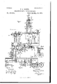
- Figure l is a frontview of the machine, partly in section.
- Fig. 2 is a vertical section of the machine on the line X X of Fig. 1.
- Fig. 3 is a horizontal section of the machine on the line Y Y of Fig. 1.
- Figs. 4, 5, and 6 show vertical sections and top view of the receiving-plate holder on an enlarged scale.
- Fig. 7 is a vertical section, enlarged, showing the lifting device, friction-clamp, and stops.
- Fig. 8 shows the locking device of the starting-gear.
- Fig. 9 shows the starting-gear.' Fig.
- FIG. 10 shows a front view of the device which operates the clutch on the main driving-pulley, and also the device for unlocking the revolving head.
- Fig. 11 is an end view of the same, showing the device which looks the revolving head.
- Fig. 2 shows one of the segmental gears which cause the turnover-plate holder to revolve.
- Fig. 14 is a top view of the same, and
- Fig. 15 is a cross-section on the line T T of.
- I 1 is the main frame of the machine, in the form of a table with legs.
- each of these plates has a strip fixed to one of its edges, having groove 9 formed in it.
- a strip Fig. 13 is a ver-' holds it.
- a spring (not shown) forces the strip endwise and holds the catch in its notch.
- the capsule-molds are in the shape of pins 13, fixed to the plates 11.
- the edges of the mold plates fit into grooves 9 and 9', which hold the mold-plates While the receiving-plate holder is being turned about the shaft 3, but
- a disk 4 is fixed to the shaft 3 and to the standard 2, and has a notch 15 formed in it, which receives latch 16.
- This latch works freely'in a slot formed in a yoke 17, fixed to the plate 7.
- the latch is pivoted at its lower end and is pressed into the notch by a spring 18.
- a handle 6, fixed to the latch, serves to draw the latch out of the notch and at the same time turn the plate-holder over.
- a similar latch and handle is fixed to both plates 7.
- Next to and in line with the receiving-plate holder 7 is the dipping-plate holder 19, having grooves at its edges like those on the receivingplate holder.
- the grooves in both holders register with each other, so that the mold-plates can be pushed from one to the other.
- the dipping-plate holder 19 is supported by rods 20, which are guided to move vertically by the blocks 21, fixe'd to the standard 31.
- a cross-head 22 connects the rods together.
- the weight of the dipping-plate holder is counterbalanced by a weight or spring through the rod or rods 23.
- the motion of the holder is limited in its downward direction by the cross-head 22 coming in contact with the point of the adjusting-screw 24, Fig. 7. It is limited in its upward movement by the cross-head coming in contact with the hook 25. This hook is pivoted to the frame of the machine at26, Fig.
- An endless belt 29 receives continuous regulated speed from a pulley not shown.
- This belt passes round a pulley 30, journaled in the standard 31, forming part of the frame of the machine.
- One part of the belt 29 travels vertically upward close to the cross-head 22 and between it and the clamp 32, Fig. 7.
- This clamp is pivoted to the end of the short arm 33 of a bell-crank, which is pivoted to the cross-head at 34.
- the long arm of the bell-lever 35 passes through a slot in the cross-head, and a wire or chain 36 is connected to its end and extends downward to a convenient distance to be reached by the operator.
- a spring 37 holds the arm 35 up and holds the clamp 32 away from the belt 29.
- a vessel 38 Directly below the dipping plate holder 19 is a vessel 38, .containin g liquid gelatine.
- This invention is not confined to any particular form or construction of vessel.
- the vessel shown and described in Letters Patent No. 316,896, to F. A. Hubel and F. Reinhold, is well adapted for use in the present invention.
- the liquid gelatine is kept at a constant level and in motion by a circulating device similar to that shown in said Patent No. 316,896, which may be driven by a pulley 39 and belt from any revolving shaft.
- the vessel may be heated by a gas-jet 40.
- the turnover-plate holder 41 Next to the dipping-plate holder 19 and registering with it is the turnover-plate holder 41.
- This holder 41 has grooved edges like those on the holder 19, so that the mold-plates may he slid from one to the other.
- the turn-over-plate holder 41 is fixed to a. shaft 42, which is journaled in a revolving head 43. This head is fixed to the shaft 44, j ournaled in the standard 45, fixed to the frame.
- a bevel-gear 46 is attached to the shaft 44 and engages the pinion 47, fixed to the shaft 48.
- This shaft is journaled in hangers 49 and 50, which are fixed to the frame.
- the pulley 51 revolves loosely on the shaft 48 and has clutch teeth formed on its hub, as clearly shown in Fig. 14.
- the clutch 52 is connected to the shaft 48 by feathers, so that it can move lengthwise on but cannot turn on the shaft.
- a spring 55 bears against the collar 53 and forces the clutch into engagement with the clutch on the pulley 51.
- a bar 56 is fixed to the clutch 52 and passes freely through an opening in the collar 53, and has fixed to its end an inclined lug 57, as shown in Fig. 13.
- a similarlug 58, with reversed incline, is fixed to the hub of the arm 54. The arm is normally held in one position by the link 59, Figs. 11, 13, and 14, so that as the shaft 48 revolves the inclined lug 57 rides up onto the inclined lug 58 and this draws the clutch 52 out of en gagement with the pulley.
- a weight 60 (see Fig. 1) is fixed to the shaft 48 by an arm placed, preferably, in such a position that the weight is traveling downward when the clutch is being drawn apart by the inclines. the first part of the revolution of the weight having been made while the clutch is in engagement.
- This weight acts by its inertia to carry the shaft forward slightly at the end of each revolution, and thus draw the clutch apart positively, the inclined faces of the lugs 57 and 58 being so proportioned in relation to the length of the clutch-teeth in engagement that when brought into the position shown in Fig. 14 the clutch-teeth will be entirely separated.
- One arrangement for turningthe plate-holder 41 is shown in the drawings, and consists of a ring 61, concentric with the shaft 44 and fixed to the standard 45.
- the upper operative surface of this ring is the frustum of a cone having its apex at the intersection of the center lines of shafts 42 and 44.
- recesses 62 formed in this ring, which may be filled with blocks, making the conical surface continuous, or by segmental gear-blocks similar to those shown at 63, Fig. 12.
- pinions 64 Fixed to the shafts 42 are pinions 64, having two opposite fiat sides and gear-teeth on the remaining two sides. These teeth intermesh with those of the segmental gears 63, and as the head 43 revolves causes the shaft 42 to make a half-revolution. So long as either flat side of the pinion 64 is in contact with the conical surface of the ring 61 the shaft 42 is held against turning and the plateholder 41 is held in a horizontal position with the mold-pins standing either vertically up or vertically down.
- the plain and gear blocks 63 are interchangeable, so that any desired combination may be had.
- the plate-holders come to rest at the points A, B, and G, and the molds may be removed at either B or C, but are generally removed at C.
- a lever 65 is pivoted to the frame 31.
- One end of the lever projects in toward the plate-holder 19.
- the end of the lever has a detent 66 pivoted to it, which may be raised, but cannot be depressed without moving the lever 65 with it.
- a lug 67 projects from the plate-holder 19, and as the latter is depressed the lug engages the detent 66 and forces it' and the end of the lever 65 downward, or the plate-holder itself may strike the detent with the same efiect. As the lug 67 travels downward, the detent travels out of engagement with the lug and the lever65 flies back to the position shown in Fig. 2.
- a rod 68 Connected to the other end of the lever 65 is a rod 68, which passes down through the table 1, and is connected to a bolt 69, which is guided in a bracket 7 O and pressed downward by a spring 71, Figs. 8 and 9.
- a shaft 72 is journaled at one end in the hanger 50 and at the other end in the hollow sleeve 73,which sleeve is journaled in the bracket 74, fixed to the frame 1.
- This sleeve isfixed to and receives continuous rotation from the pulley 75 by means of a belt from any revolving shaft, and is frictionally connected with the shaft, which moves intermittently by means of the following mechanism.
- a collar 76 isfixed to the shaft 72 and bears against one end of the sleeve 7 3. which engages the bolt 69.
- a disk 78 is mounted on the shaft 72, adjacent to the pulley 75, so as to slide on it and turn with it.
- a cam 81 Fixed to the shaft 72 is a cam 81, Figs. 10 and 11.
- This cam acts upon an arm 82,fixed to the shaft 83, journaled in the'frame.
- An arm 84 is also fixed to the shaft 83 and has its end connected by a rod 85 to a bolt 86.
- the end of the bolt 86 strikes a lug 89, fixed to each of the arms of the head 43 and stops the turn-over-plate holder positively in register with the dipping-plate holder.
- the bolt is drawn down, it is held down by the catch 90, pivoted to the bar 87 and extending This collar has a lug 77 on it,.
- a spring 88 serves to force the bolt 86 upward when the latter is released.
- a lug (not shown) on each arm of the revolving head 43 forces the catch 99 back before the plate-holder 41 arrives at the position of rest.
- A which permits the spring 88 to force the bolt 86 up and stop the revolving head, so that the plate-holder 41 registers exactly with the plate-holder 19.
- a crank-pin 91 fixed to the shaft 72, is connected by the link 59 with the arm 54, Fig. 2.
- the operation of the machine is as follows: The locking-strip 10 of the upper receivingplate holder 7 is turned down. A mold-plate or set of plates is placed on the plate-holder and the locking-strip 10 closed. The plateholders 7 are then unlocked and turned over by the upper handle 6. The mold-plate is then slid into the dipping-plate holder 19 and at the same time a second plate is put into the receiving-plate holder 7 and turned over. The dipping plate holder is now pressed down and the molds immersed in the liquid gelatine until stopped by the screw 24. The end of the chain 36 is pulled down, clamping the cross-head 22 to the belt 29.
- the molds are thus drawn slowlyout of the liquid gelatine, and when the ends of the molds -leave the gelatine the pressure is let off the clamp and the plate-holder rises quickly to its upper position and is stopped bythe hook 25.
- the molds in the receiving-plate holder 7 are now slid into the dipping-plate holder 19, which forces thosein the dipping-plate holder into the turn-over holder 41.
- a new moldplate is laid in and turned over and the dipping-plate holder depressed, as before. 'As the dipping plate holder moves down, it catches the lever 65 and carries it down, which draws the bolt- 69' and unlocks the shaft 72.
- the shaft makes one revolution and is stopped again by the bolt 69, which has come back to its first position.
- the shaft 72 causes the cam 81 to draw the bolt and unlock the revolving head, and the bolt is held down by the catch 9.0.
- the shaft 72 in revolving causes the crank-pin 91 to draw the lever 54 back and allows the clutch 52 to engage the pulley, which causes the turning head to revolve.
- a lug on the revolving head forces the catch back and releases the bolt 86 in time to stop the plate-holder 41 just in register with the dipping-plate holder 19.
- the plate-holders ll may be turned over continuously or intermittently or not turned at all, according to the arrangement of the blocks and the segmental gears in the recesses 62 of the ring 61. iVhenever the revolving head stops, the mold-plates may be removed at either the position B or C.
- a fixed receiving-plate holder may be used, into which the plate may be slid by hand with its pins pointing downward, and thence he slid into the dipping-plate holder, or the'receiving-plate holder may be dispensed with entirelyand theplatesslid,pins down,into the dipping-plate holder.
- the turnover-plate holders instead of being attached to a head revolvingin ahorizontal plane, may be attached to one which revolves in a vertical plane either about a central axis or carsuch a manner as to produce an'operative although not an automatic machine, the respective combinations being actuated by hand.
- a rotary receiving-plate holder turning upon a fixed axis attached to the standard on the frame, provided with receiving-grooves on opposite faces, whereby mold-plates can be received on the upper side and moved so as to turn the points of the pins down, substantially as set forth.
- a receiving-plate holder In a machine for dipping gelatine capsules, a receiving-plate holder, a verticallymovable dipping-piate holder, and an intermittently-rotating and turning plate-holder, all in the same plane, substantially as shown and described.
Landscapes
- Engineering & Computer Science (AREA)
- Mechanical Engineering (AREA)
Description
(No Model.)
, 4 ShetsSheet 1. F. A. HUBEL. GELATINE CAPSULE DIPPING MACHINE. N0. 465,933.
Patented Deg. 29, 1891.
W R m 0 M. m 5. M m m Z 71 0 o f H Gm n 7 v N w] (No Model.)
41Shets-Sheet 2. .F'. A. HUBEL.
GELATINE CAPSULE DIPPING MACHINE. No; 465,933.
Patented Dec 29, 1891.
"m: mum: PETER! co., PHOTO-LINE, msnmaron, n. c.
(No Model.)
4 Sheets-Sheet 3.
I'.A.HUBE-L. GELATINB CAPSULE DIPPING MACHINE.
No. 465,933. Patented Dec. 29, 1891.
17V VEW T 0 mom-L MC QQWM WITWESSE'S (No Model.) 4 Sheets-SheetA.
F. A. HUBEL.
GE'LATINE CAPSULE DIPPING MACHINE.
Patented-Dec. 29, 1891.
IIIIIIII WITNESSES INVEWZZQ;
Figs. 1, 5,and 6.
PATENT FFICE.
FREDERICK A. HUBEL, OF DETROIT, MICHIGAN GELATINE-CAPSULE-YDIPPING MACHINE.
SIECIFZCATION forming part of Letters Patent No. 465,933, dated December 29, 1891.
Application filed September 12, 1890. Serial No. 364,793. (No model.)
To all whom it may concern:
Be it known that I, FREDERICK A. Human, of Detroit, in the county of Wayne and State of Michigan, have invented new and useful Improvements in Gelatine-Oapsule-Dipping Machines, of which the following is a speci-' fication.
This invention relates to a machine for dipping capsule-molds in a solution of gelatine and setting the gelatine on the molds preparatory to cutting and drying.
In the annexed drawings, making part of this specification, Figure l is a frontview of the machine, partly in section. Fig. 2 is a vertical section of the machine on the line X X of Fig. 1. Fig. 3 is a horizontal section of the machine on the line Y Y of Fig. 1. Figs. 4, 5, and 6 show vertical sections and top view of the receiving-plate holder on an enlarged scale. Fig. 7 is a vertical section, enlarged, showing the lifting device, friction-clamp, and stops. Fig. 8 shows the locking device of the starting-gear. Fig. 9 shows the starting-gear.' Fig. 10 shows a front view of the device which operates the clutch on the main driving-pulley, and also the device for unlocking the revolving head. Fig. 11 is an end view of the same, showing the device which looks the revolving head. Fig. 2 shows one of the segmental gears which cause the turnover-plate holder to revolve. tical longitudinal section of the clutch mechanism. Fig. 14: is a top view of the same, and
Fig. 15 is a cross-section on the line T T of.
Fig. 14.
Like numbers indicate like parts in all the drawings.
I 1 is the main frame of the machine, in the form of a table with legs.
2 is a standard fixed to the frame having a horizontal shaft 3 fixed in its upper end, Mounted on the shaft 3 so as to turn freelyupon it are two blocks 8, to which blocks are fixed two flat plates 7. Each of these plates has a strip fixed to one of its edges, having groove 9 formed in it. On the opposite side of each plate 7 there is a strip Fig. 13 is a ver-' holds it. A spring (not shown) forces the strip endwise and holds the catch in its notch.
The capsule-molds are in the shape of pins 13, fixed to the plates 11. The edges of the mold plates fit into grooves 9 and 9', which hold the mold-plates While the receiving-plate holder is being turned about the shaft 3, but
permit the mold-plates to be slid in the direction of the grooves. A disk 4 is fixed to the shaft 3 and to the standard 2, and has a notch 15 formed in it, which receives latch 16. This latch works freely'in a slot formed in a yoke 17, fixed to the plate 7. The latch is pivoted at its lower end and is pressed into the notch by a spring 18. A handle 6, fixed to the latch, serves to draw the latch out of the notch and at the same time turn the plate-holder over. A similar latch and handle is fixed to both plates 7. Next to and in line with the receiving-plate holder 7 is the dipping-plate holder 19, having grooves at its edges like those on the receivingplate holder. The grooves in both holders register with each other, so that the mold-plates can be pushed from one to the other. The dipping-plate holder 19 is supported by rods 20, which are guided to move vertically by the blocks 21, fixe'd to the standard 31. A cross-head 22 connects the rods together. The weight of the dipping-plate holder is counterbalanced by a weight or spring through the rod or rods 23. The motion of the holder is limited in its downward direction by the cross-head 22 coming in contact with the point of the adjusting-screw 24, Fig. 7. It is limited in its upward movement by the cross-head coming in contact with the hook 25. This hook is pivoted to the frame of the machine at26, Fig. 7, and is held in the position shown by a spring 27, acting on the arm 28, made fast to the hook 25. The hook may be drawn back out of engagement with the cross-head 22 by pulling down on the end of arm 28, which will permit the holder 19 to move up higher, as it is desirable at times.
It is necessary that the molds be raised at a regular speed, and one means for doing this is fully set forth in Reissued Letters Patent to F. A. Hubel and H. H. Taylor, No. 10,316. The clamping of the belt to the plate-holder in that machine was performed manually. In
IOC
this machine the clamping of the belt is per formed by mechanical means. An endless belt 29 receives continuous regulated speed from a pulley not shown. This belt passes round a pulley 30, journaled in the standard 31, forming part of the frame of the machine. One part of the belt 29 travels vertically upward close to the cross-head 22 and between it and the clamp 32, Fig. 7. This clamp is pivoted to the end of the short arm 33 of a bell-crank, which is pivoted to the cross-head at 34. The long arm of the bell-lever 35 passes through a slot in the cross-head, and a wire or chain 36 is connected to its end and extends downward to a convenient distance to be reached by the operator. A spring 37 holds the arm 35 up and holds the clamp 32 away from the belt 29. lVhen the chain 36 is drawn down, the clamp is forced against the belt and pinches itagainst the cross-head, so that whatever motion the belt 29 may have is given to the dipping-plate holder. \Vhen the chain 36 is released, the plate-holder is free to move independent of the belt.
Directly below the dipping plate holder 19 is a vessel 38, .containin g liquid gelatine. This invention is not confined to any particular form or construction of vessel. The vessel shown and described in Letters Patent No. 316,896, to F. A. Hubel and F. Reinhold, is well adapted for use in the present invention. The liquid gelatine is kept at a constant level and in motion by a circulating device similar to that shown in said Patent No. 316,896, which may be driven by a pulley 39 and belt from any revolving shaft. The vessel may be heated by a gas-jet 40. Next to the dipping-plate holder 19 and registering with it is the turnover-plate holder 41. This holder 41 has grooved edges like those on the holder 19, so that the mold-plates may he slid from one to the other. The turn-over-plate holder 41 is fixed to a. shaft 42, which is journaled in a revolving head 43. This head is fixed to the shaft 44, j ournaled in the standard 45, fixed to the frame. A bevel-gear 46 is attached to the shaft 44 and engages the pinion 47, fixed to the shaft 48. This shaft is journaled in hangers 49 and 50, which are fixed to the frame. The pulley 51 revolves loosely on the shaft 48 and has clutch teeth formed on its hub, as clearly shown in Fig. 14. The clutch 52 is connected to the shaft 48 by feathers, so that it can move lengthwise on but cannot turn on the shaft.
53 is a collar fixed to the shaft 48.
54 is an arm journaled on the collar 53, so that it may be turned without moving the collar.
A spring 55 bears against the collar 53 and forces the clutch into engagement with the clutch on the pulley 51. A bar 56 is fixed to the clutch 52 and passes freely through an opening in the collar 53, and has fixed to its end an inclined lug 57, as shown in Fig. 13. A similarlug 58, with reversed incline, is fixed to the hub of the arm 54. The arm is normally held in one position by the link 59, Figs. 11, 13, and 14, so that as the shaft 48 revolves the inclined lug 57 rides up onto the inclined lug 58 and this draws the clutch 52 out of en gagement with the pulley.
A weight 60 (see Fig. 1) is fixed to the shaft 48 by an arm placed, preferably, in such a position that the weight is traveling downward when the clutch is being drawn apart by the inclines. the first part of the revolution of the weight having been made while the clutch is in engagement. This weight acts by its inertia to carry the shaft forward slightly at the end of each revolution, and thus draw the clutch apart positively, the inclined faces of the lugs 57 and 58 being so proportioned in relation to the length of the clutch-teeth in engagement that when brought into the position shown in Fig. 14 the clutch-teeth will be entirely separated. This continued movement given to the shaft 48 by the 1211s inertia of the weight completely separating the teeth of the clutch prevents their chattering, as they would do if their separation depended entirely on the action of the inclines. When the flat faces of the inclined lugs 57 and 58 are brought into the position shown in Fig. 14, the forward movement of the weight will be stopped positively, in which position it will stand until the descent of the clipping-plate will, in a manner hereinafter to be described, cause the arm 54 to be thrown forward far enough, so that the inclined lugs 57 and 58 are disengaged, when the spring will instantly throw the clutch 52 into engagement with the hub or pulley 51, and the shaft 48 will receive another revolution. There are two or more turn-over-plate holders like 41. Three are shown, Fig. 3; but any number may be used.
It is necessary that the molds be turned over while the liquid gelatine is setting, so that the capsules will be of even thickness, and they may require to be turned at different intervals of time according to the state of the atmosphere. One arrangement for turningthe plate-holder 41 is shown in the drawings, and consists of a ring 61, concentric with the shaft 44 and fixed to the standard 45. The upper operative surface of this ring is the frustum of a cone having its apex at the intersection of the center lines of shafts 42 and 44. At convenient intervals there are recesses 62, formed in this ring, which may be filled with blocks, making the conical surface continuous, or by segmental gear-blocks similar to those shown at 63, Fig. 12. Fixed to the shafts 42 are pinions 64, having two opposite fiat sides and gear-teeth on the remaining two sides. These teeth intermesh with those of the segmental gears 63, and as the head 43 revolves causes the shaft 42 to make a half-revolution. So long as either flat side of the pinion 64 is in contact with the conical surface of the ring 61 the shaft 42 is held against turning and the plateholder 41 is held in a horizontal position with the mold-pins standing either vertically up or vertically down. The plain and gear blocks 63 are interchangeable, so that any desired combination may be had. The plate-holders come to rest at the points A, B, and G, and the molds may be removed at either B or C, but are generally removed at C. It is desiralole that the machine may be operated with as little loss of time as possible, and at the same time be positive in its operation. To this end it should be under the control of one person, so that the depression of the dippingplate holder and the starting of the revolving head may be done by one operation. A lever 65, Fig. 2, is pivoted to the frame 31. One end of the lever projects in toward the plate-holder 19. The end of the lever has a detent 66 pivoted to it, which may be raised, but cannot be depressed without moving the lever 65 with it. A lug 67 projects from the plate-holder 19, and as the latter is depressed the lug engages the detent 66 and forces it' and the end of the lever 65 downward, or the plate-holder itself may strike the detent with the same efiect. As the lug 67 travels downward, the detent travels out of engagement with the lug and the lever65 flies back to the position shown in Fig. 2. Connected to the other end of the lever 65 is a rod 68, which passes down through the table 1, and is connected to a bolt 69, which is guided in a bracket 7 O and pressed downward by a spring 71, Figs. 8 and 9. A shaft 72 is journaled at one end in the hanger 50 and at the other end in the hollow sleeve 73,which sleeve is journaled in the bracket 74, fixed to the frame 1. This sleeve isfixed to and receives continuous rotation from the pulley 75 by means of a belt from any revolving shaft, and is frictionally connected with the shaft, which moves intermittently by means of the following mechanism. A collar 76 isfixed to the shaft 72 and bears against one end of the sleeve 7 3. which engages the bolt 69. A disk 78 is mounted on the shaft 72, adjacent to the pulley 75, so as to slide on it and turn with it. This may be accomplished by making the end of the shaft square and forming a square eye in the disk or other equivalent means. The disk is pressed against the other end of the sleeve 73 by the spring 79, which may be regulated by the'thumb-nut S0. of the collar 76 and disk 78 on the. sleeve 73 tends to revolve the shaft 72 with the sleeve 7 3,and it will so revolve whenever the bolt 69 releases it.
Fixed to the shaft 72 is a cam 81, Figs. 10 and 11. This cam acts upon an arm 82,fixed to the shaft 83, journaled in the'frame. An arm 84 is also fixed to the shaft 83 and has its end connected by a rod 85 to a bolt 86. The end of the bolt 86 strikes a lug 89, fixed to each of the arms of the head 43 and stops the turn-over-plate holder positively in register with the dipping-plate holder. \Vhen the bolt is drawn down, it is held down by the catch 90, pivoted to the bar 87 and extending This collar has a lug 77 on it,.
The friction up through the standard 45. A spring 88 serves to force the bolt 86 upward when the latter is released. A lug (not shown) on each arm of the revolving head 43 forces the catch 99 back before the plate-holder 41 arrives at the position of rest. A, which permits the spring 88 to force the bolt 86 up and stop the revolving head, so that the plate-holder 41 registers exactly with the plate-holder 19. A crank-pin 91, fixed to the shaft 72, is connected by the link 59 with the arm 54, Fig. 2. When the shaft'72 makes one revolution, the end of the arm 54 is moved and returned to its first position, which causes the inclined lug 58 to travel past the lug 57, and thuspermits the clutch 52 to engage the pulley 51.
The operation of the machine is as follows: The locking-strip 10 of the upper receivingplate holder 7 is turned down. A mold-plate or set of plates is placed on the plate-holder and the locking-strip 10 closed. The plateholders 7 are then unlocked and turned over by the upper handle 6. The mold-plate is then slid into the dipping-plate holder 19 and at the same time a second plate is put into the receiving-plate holder 7 and turned over. The dipping plate holder is now pressed down and the molds immersed in the liquid gelatine until stopped by the screw 24. The end of the chain 36 is pulled down, clamping the cross-head 22 to the belt 29. The molds are thus drawn slowlyout of the liquid gelatine, and when the ends of the molds -leave the gelatine the pressure is let off the clamp and the plate-holder rises quickly to its upper position and is stopped bythe hook 25. The molds in the receiving-plate holder 7 are now slid into the dipping-plate holder 19, which forces thosein the dipping-plate holder into the turn-over holder 41. A new moldplate is laid in and turned over and the dipping-plate holder depressed, as before. 'As the dipping plate holder moves down, it catches the lever 65 and carries it down, which draws the bolt- 69' and unlocks the shaft 72. The shaft makes one revolution and is stopped again by the bolt 69, which has come back to its first position. The shaft 72, as it revolves, causes the cam 81 to draw the bolt and unlock the revolving head, and the bolt is held down by the catch 9.0. At the same time the shaft 72 in revolving causes the crank-pin 91 to draw the lever 54 back and allows the clutch 52 to engage the pulley, which causes the turning head to revolve. Before either of the turn-over-plate holders 41 arrive at the IIO position of rest A a lug on the revolving head forces the catch back and releases the bolt 86 in time to stop the plate-holder 41 just in register with the dipping-plate holder 19. Just before the plate-holder 41 arrives in this position the inclined lug 57 climbs up onto the lug 58 and draws the clutch apart; but the motion is continued by the weight 60 till the revolving head is brought to a positive stop by the bolt 86. This operation is repeated at each depression of the dippingplate holder 19. When the revolvinghead is in motion, the plate-holders ll may be turned over continuously or intermittently or not turned at all, according to the arrangement of the blocks and the segmental gears in the recesses 62 of the ring 61. iVhenever the revolving head stops, the mold-plates may be removed at either the position B or C.
It is obvious that many changes in the relative positions of the elements and in the elements themselves may be made without departing from the spirit of this invention. Thus, instead of having the spring 37 to act on the clamps 33' to hold it away from the belt, an arm may be projected on the opposite side and a weight placed thereon. So, also, while it is regarded as preferable that the weight shall be descending when the clutch disengages the pulley the speed of the shaft and the gravity of the weight may be so regulated that it will operate in the same manner it the disengagement takes place while the weight is ascending and the weight is arrested at the upper part of its revolution. So instead of having the segmental gear-blocks detachably placed in sockets in the ring permanent gear-teeth may be cast on the face of the ring. So, also, instead of a lug 67 on the reciprocating dipping-plate holder, there may be used any other means of tripping the lever with the movement either of the reciprocating plate or of areciprocating gelatine-vessel. Boththe plate and gelatine vessel may and have been made movable, the only essential thingbein g that the molds shallbeimmersed in the gelatine to the requisite depth to form the capsule. So, also, instead of a rotary receiving-plate holder, a fixed receiving-plate holder may be used, into which the plate may be slid by hand with its pins pointing downward, and thence he slid into the dipping-plate holder, or the'receiving-plate holder may be dispensed with entirelyand theplatesslid,pins down,into the dipping-plate holder. So, also, the turnover-plate holders, instead of being attached to a head revolvingin ahorizontal plane, may be attached to one which revolves in a vertical plane either about a central axis or carsuch a manner as to produce an'operative although not an automatic machine, the respective combinations being actuated by hand. Othercomhinationsweresubsequently added to those herein claimed by myself and Jesse M. Smith, as set forth in our joint application, Serial No. $645,782, and others by said Jesse M. Smith alone, as set forth in his application, Serial No. 36l,770. Those combinations are covered by claims in other applications made concurrently with this upon identical drawings, each showing the entire machine, the respective claims of the several applications being made according to the fact of joint or sole invention, and I herein disclaim all the combinations set forth in either of the said concurrent applications.
Vhat I claim as my invention, and desire to secureby Letters Patent, is-
1. In combination with a capsule-dipping machine, a rotary receiving-plate holder turning upon a fixed axis attached to the standard on the frame, provided with receiving-grooves on opposite faces, whereby mold-plates can be received on the upper side and moved so as to turn the points of the pins down, substantially as set forth.
2. In combination with the dipping-plate holder, a reversible receiving-plate holder, and means for turning the mold-plate down so that the plate-grooves of the latter shall register with the grooves of the former, substantially as set forth.
In combination with a dippingplate holder 19, the turn-over-plat e holder 41, registering with it when stopped, substantially as set forth.
4. In a machine for dipping gelatine capsules, the combination, with a vertically-movable dipping-plate holder, of an intermittently-rotating and turning plate-holder registering with the dipping-plate holder at the upper end of its stroke, substantially as shown and described.
5." In a machine for dipping gelatine capsules, a receiving-plate holder, a verticallymovable dipping-piate holder, and an intermittently-rotating and turning plate-holder, all in the same plane, substantially as shown and described.
In testimony whereof I havehereunto signed my name in the presence of two attesting witnesses.
FREDERICK A. IIUBEL.
\Vitnesses'.
RODNEY hIASON, M. A. Howm.
Publications (1)
| Publication Number | Publication Date |
|---|---|
| US465933A true US465933A (en) | 1891-12-29 |
Family
ID=2534797
Family Applications (1)
| Application Number | Title | Priority Date | Filing Date |
|---|---|---|---|
| US465933D Expired - Lifetime US465933A (en) | Gelatine-capsule-dipping machine |
Country Status (1)
| Country | Link |
|---|---|
| US (1) | US465933A (en) |
-
0
- US US465933D patent/US465933A/en not_active Expired - Lifetime
Similar Documents
| Publication | Publication Date | Title |
|---|---|---|
| US465932A (en) | hubel | |
| US465951A (en) | Gelatine capsule dipping machine | |
| US757737A (en) | Slide-feeding device for picture-projecting apparatus. | |
| US432903A (en) | sagoo | |
| US546160A (en) | Machine for turning irregular forms | |
| US437751A (en) | Machine for the manufacture of crayons | |
| US444487A (en) | Fisher | |
| US940479A (en) | Apparatus for viewing stereoscopic or other pictures. | |
| US701116A (en) | Machine for making buttons. | |
| US486591A (en) | Machine for grinding drinking-glasses | |
| US429707A (en) | Churn | |
| US300882A (en) | Drain-tile machine | |
| US747428A (en) | Glass-cutting machine. | |
| US540902A (en) | bryce | |
| US1072917A (en) | Type-casting and similar machine. | |
| US587221A (en) | Automatic photographic appakatus | |
| US463370A (en) | hunter | |
| US1188560A (en) | Automatic stop mechanism. | |
| US1372733A (en) | Cinematograph apparatus and intermittent-feed mechanism therefor | |
| US667413A (en) | Cheese case and knife. | |
| US781377A (en) | Automatic photo-machine. | |
| US323753A (en) | taylor | |
| US744928A (en) | Panoramic camera. | |
| US737792A (en) | Machine for forming butter pats. | |
| US693145A (en) | Machine for justifying type. |