US465805A - smith - Google Patents
smith Download PDFInfo
- Publication number
- US465805A US465805A US465805DA US465805A US 465805 A US465805 A US 465805A US 465805D A US465805D A US 465805DA US 465805 A US465805 A US 465805A
- Authority
- US
- United States
- Prior art keywords
- circuit
- sections
- switch
- wire
- brushes
- Prior art date
- Legal status (The legal status is an assumption and is not a legal conclusion. Google has not performed a legal analysis and makes no representation as to the accuracy of the status listed.)
- Expired - Lifetime
Links
- 239000004020 conductor Substances 0.000 description 60
- 230000000694 effects Effects 0.000 description 5
- 239000002184 metal Substances 0.000 description 3
- 230000004075 alteration Effects 0.000 description 2
- 238000010276 construction Methods 0.000 description 2
- 230000002093 peripheral effect Effects 0.000 description 2
- 230000005611 electricity Effects 0.000 description 1
- 230000008520 organization Effects 0.000 description 1
Images


Classifications
-
- H—ELECTRICITY
- H01—ELECTRIC ELEMENTS
- H01R—ELECTRICALLY-CONDUCTIVE CONNECTIONS; STRUCTURAL ASSOCIATIONS OF A PLURALITY OF MUTUALLY-INSULATED ELECTRICAL CONNECTING ELEMENTS; COUPLING DEVICES; CURRENT COLLECTORS
- H01R31/00—Coupling parts supported only by co-operation with counterpart
Definitions
- WITNESSES ing On and Off Electric Currents, of which UNITED STATES PATENT OFFICE.
- THOMAS CARPENTER SMITH a subject of the Queen of Great Britain, residing in the city and county of Philadelphia, in the State of Pennsylvania
- BENJAMIN D. ACKER a citizen of the United States, and likewise a resident of the city and county of Philadelphia, in the State of Pennsylvania, have jointlyinvented certain new and useful Improvements in Means forTurnthe following is a specification.
- Our invention relates to the means for 10- cally controlling or turning on or off an electric current set up in a circuit utilized for any desired purpose, and relates especially to such currents as are employed to energize a series of electric lights.
- Fig. 2 is a front elevational View of one of the switches resorted to in connection with the practice of our invention, the cover being supposed removed to exhibit its construction.
- Fig. 23 is a detail view in perspective of the drum of said switch.
- Fig. 7 is as stated a diagrammatic view of a form of circuit opening and closing arrangement heretofore in use.
- ourinvention comprehends the provision and employment at any preferred part of an electric circuit, of a double series of conducting sections, united by associated switches into a continuous system, the individual members of which double series, under the government of the switches, are thrown variously into circuit with either the one or the other or both of the main wires, or constitute temporarily with others a dead circuit.
- A is the cut out or starting point of a circuit
- B C are the respective wires leading therefrom to form a circuit for the energizing of a series of lamps Q supposed located upon the different floors of a multi-storied residence.
- b b b are a series of conductor sections
- c c c c are a corresponding series of conductor sections.
- D is a three point switch at the extremity of the wire B
- E is a three point switch at the end of the wire 0.
- the wires or conductor sections 12' c are each as to one extremity connected with one of the points of the switch D, and the wires or conductor sections b and c are each as to one extremity connected with one of the points of the switch E.
- the wires 1) c and the wires 1) c are connected by adevice by which said wire I) is adapted to be placed and held in circuit with either the wire 1) or c ,-and by which said wire 0' is adapted to be placed and held in circuit with either the wire I) or c ,the arrangementbeing such that when the wire 1) isin circuit with the wire b the wire 0 is necessarily in circuit with the wire c ,while on the other hand if the wire I) is in circuit with the wire 0 the wire 0 is necessarily in circuit with the wire b
- This connection is effected by a form of switch contrivance of our invention, whereof hereinafter.
- a similar switch arrangement is made with regard to the contiguous ends of the wires 19 c and b c ,and with regard to the contiguous ends of the wires 11 c and b c,and so on for as many conductor sections as may be employed.
- each pair of companion conductor sections of such length as to extend from each floor to that above or below it, so that one of the switches may be located upon each floor, by which arrangement it is obvious that regardless of the floor from which the circuit is closed it may be opened from any, and on the other hand regardless of the floor from which the circuit is opened it may be closed from any. It is obvious that the arrangement is of utility in connection with IIO circuits utilized for other purposes than lighting, and also obvious that any desired number of conductor sections made in any desired lengths may be employed.
- G is the base plate of the switch, for instance No. 1, upon the face of which are located four binding posts, h, i, j, and 7a, to which binding posts are respectively secured the four conductor or switch sections 11 c b 0
- Each of the posts conveniently supports or is provided with a bracket or arm, respectively designated h t j and 7t, and upon each arm is mounted a brush which latter are re spectively designated 7L2 '6 7' k
- the brushes are secured at their outer ends upon their respective brackets while their bodies and free extremities extend inwardly to the drum or commutator, the arrangement being such that the brushes 7L2.
- j are contiguous to each other but not in contact, on one side of the commutator, so as to both tread on a common face of said commutator,while the brushes 2' 7C2 are similarly contiguous to each other but notin contact, on the opposite side of the commutator, so'as to both similarly tread upon a common face thereof.
- L is the drum or commutator, mounted conveniently upon so as to be rotated with a spindle M, provided with a key m at its outer end and entered in the plate G.
- the periphery of said commutator embodies four segmental eccentric faces Z Z Z Z the point of greatest projection or crest of each being circumferentially succeeded by the place of least projection of its neighbor, whereby shoulders are formed which prevent a brush from making contact with two faces at once.
- Each of the faces Z and Z is covered by a plate of conducting material Z and the faces 1 and Z each bear a pair of strips, one, Z at the outer end, and the other, Z, at the inner end, of the commutator.
- the plates Z are insulated from each other and from the strips, but the two strips Z are connected by a conductor Z and the two strips Z are connected by a conductor Z both which conductors conveniently extend through the body of the commutator.
- the commutator shown is designed to be turned only to the right, as rotation in the other direction would be prevented by the contact of its projections with the abutting extremities of the brushes.
- a pair of companion conductors embodying a series of interruptions by which they are divided into a succession of pairs of conductor sections, through a series of which sections consisting of one member of each of said pairs electrically connected, thecircuit of the line conductors is completed and closed, while the remaining member of each pair is out of circuit,movable conductors located at the interruptions, which maintain the two conductor sections on one side of each interruption in connection, alternately straight and cross, with the two conductors on the other side of said interruption, substantially as set forth.
- a switch in combination with conductor sections, two binding posts upon which four sections are respectively connected, brushes supported by said binding posts, a rotatable drum with which said brushes are by pairs in contact, which drum embodies independentsegmental faces alternately composed of single plates of conducting material adapt-ed to place the brushes of one pair in circuit with each othcr,and of double independent plates of conducting material respectively connected with corresponding plates on another face of the drum and adapted to place brushes of one pair in circuit with brushes of an opposite pair, substantially as set forth.
- a switch provided with a rotatable drum and with binding posts to which the sections are respectively connected, brushes supported by said binding posts, which brushes are by pairs in tread upon different peripheral portions of said drum, said drum being formed with faces, which are successively or alternately provided with insulated plates of metal, and with pairs of strips which are in connection with pairs of strips upon the opposite face of the drum or commutator, substantially as set forth.
- a switch composed of a rotatable drum or commutator, embodying peripheral faces, half of which faces are provided with insulated plates of conducting material, and the others of which are each provided with two strips of conducting material, each of said last named strips being in circuit with corresponding strips on the other face or faces of the drum,two pairs of conductor sections, brushes with which said sections are connected, the brushes to which the first section of each respective pair of sections are connected lying close together and in tread upon one face of the drum at a time,--and the brushes to which the second section of each respective pair of sections are connected, lying close together and in contact or tread upon one face of the drum at a time, all the brushes being always contemporaneously 1n tread upon faces of like character, substantially as set forth.
Landscapes
- Switch Cases, Indication, And Locking (AREA)
Description
3 Sheets-S heet 1.
T. 0 SMITH & B. D. AOKER.
MEANS FOR TURNING ON AND OFF ELECTRIC GURRENTS.
No. 465,805. Patented Dec. 22, 1891.
t (No Model.)
S w wy ga 1 Qdcw WITNESSES INVENTORS:
(Nb Model.) 3 Sheets-Sheet 2.
T. 0. SMITH 8513. D. ACKER. MEANS FOR TURNING ON AND OF]? ELECTRIC UURRENTS.
N0. 465,805. Patented Dec. 22, 1891.
INVENTORS: r limpcw WITNESSES 3 Sheets-'Sheet 3.
-T. 0. SMITH & B. D. AGKER. MEANS FOR TURNING ON AND OFF ELEGTRIG OURRENTS.
(No Model.)
No. 465,805. Patented Dec. 22, 1891.
j B j 6 C 06 H64. F16 5. FfG.
C1 c 6 c J I l I I X c? 53' 6-2 C2 Z22 @1 i H; INVEWRS:
WITNESSES ing On and Off Electric Currents, of which UNITED STATES PATENT OFFICE.
THOMAS CARPENTER SMITH AND BENJAMIN D. AOKER, OF PHILADELPHIA, PENNSYLVANIA, ASSIGNORS TO ISAAC C. \VALKER AND HENRY G. KER
LER, OF SAME PLACE.
MEANS FOR TURNING ON AND OFF ELECTRIC CURRENTS.
SPECIFICATION forming part of Letters Patent No. 465,805, dated December 22, 1891.
Application filed October 1, 1890.
To all whom it nutty concern:
Be it known that we, THOMAS CARPENTER SMITH, a subject of the Queen of Great Britain, residing in the city and county of Philadelphia, in the State of Pennsylvania, and BENJAMIN D. ACKER, a citizen of the United States, and likewise a resident of the city and county of Philadelphia, in the State of Pennsylvania, have jointlyinvented certain new and useful Improvements in Means forTurnthe following is a specification.
Our invention relates to the means for 10- cally controlling or turning on or off an electric current set up in a circuit utilized for any desired purpose, and relates especially to such currents as are employed to energize a series of electric lights.
Ileretofore when a series of electric lights have been established upon a common circuit diliiculty in their manipulation has been experienced in that while any number of points along the line might be provided at which the circuit could be opened, it has been necessary that the operator or user should, in turning the current on again, return to the place at which it was turned oiii, instead of being able to turn said current on or close the circuit from other points in the vicinity of which he might be along the line. Heretofore however a system has been devised of providing a pair of companion switch wires, which are both at one end connected respectively with two of the respective points of a three point switch, and are at the other end connected respectively with two of the respective points of a second three point switch, situated at a point more or less remote from the switch first named. Such an arrangement is shown in Fig. 7 of the drawings, in which \V is one and X the other three point switch, and y y the two companion switch wires. To the third point ot the switch \V the extremity of a line wire .2 is connected, and to the third point of the switch X the extremity of a line wire .2" is connected. The line wires are always each in circuit with one or the other of the switch wires, and when both line wires are connected to the same switch wire, as for example, 3 the circuit is Serial No. 366,749. (No model.)
closed. When this is the case it is evident that the rotation of either switch so as to throw the extremityof theline wire connected with it into contact with the switch wire 1 will open the circuit, and when the currentis so opened, it is apparent that the circuit can be closed at the point occupied by either switch, for the reason that one line wire being in circuit with one switch wire, and the other line wire in circuit with the other switch wire, rotation of eitherswitchwillnecessarily place its main wire in circuit with the same switch wire which is in circuit with the other line wire. This system however cannot from the nature of its organization, provide more than the two points of control indicated, and therefore does not remove the difficulty mentioned. Thus for instance when it has been resorted to in connection with the wiring of residences lighted by electricity, one switch has been placed at the top and the other at the bottom of the house, manipulationof the switches necessitating a visit to either of these points, a consideration which diminishes the convenience and therefore the desirability of electric lighting systems for 1n ulti-storied buildings.
It is the object of our invent-ion to provide an inexpensive, economical, and convenient,
means by which an electric current can be opened or closed at will from any convenient one of any desired predetermined number of points of control along a circuit, with equal facility.
In the drawings we illustrate and herein we describe a preferred form of a convenient embodiment of our invention, the particular subject matter claimed as novel being hereinat'ter definitely specified.
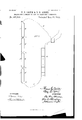
In the drawings,l igure l is a diagrammatic view of a series of electric lights, the circuit in which the same are established being provided with a preferred embodiment of our invention. Fig. 2 is a front elevational View of one of the switches resorted to in connection with the practice of our invention, the cover being supposed removed to exhibit its construction. Fig. 23 is a detail view in perspective of the drum of said switch. Figs. t,
of different positions of the switches employed in the practice of our invention. Fig. 7 is as stated a diagrammatic view of a form of circuit opening and closing arrangement heretofore in use.
Generally stated,ourinvention comprehends the provision and employment at any preferred part of an electric circuit, of a double series of conducting sections, united by associated switches into a continuous system, the individual members of which double series, under the government of the switches, are thrown variously into circuit with either the one or the other or both of the main wires, or constitute temporarily with others a dead circuit.
In Fig. 1 of the drawings, A is the cut out or starting point of a circuit, and B C are the respective wires leading therefrom to form a circuit for the energizing of a series of lamps Q supposed located upon the different floors of a multi-storied residence. 1) b b b are a series of conductor sections and c c c c are a corresponding series of conductor sections. D is a three point switch at the extremity of the wire B, and E is a three point switch at the end of the wire 0. The wires or conductor sections 12' c are each as to one extremity connected with one of the points of the switch D, and the wires or conductor sections b and c are each as to one extremity connected with one of the points of the switch E. The wires 1) c and the wires 1) c are connected by adevice by which said wire I) is adapted to be placed and held in circuit with either the wire 1) or c ,-and by which said wire 0' is adapted to be placed and held in circuit with either the wire I) or c ,the arrangementbeing such that when the wire 1) isin circuit with the wire b the wire 0 is necessarily in circuit with the wire c ,while on the other hand if the wire I) is in circuit with the wire 0 the wire 0 is necessarily in circuit with the wire b This connection is effected by a form of switch contrivance of our invention, whereof hereinafter. A similar switch arrangement is made with regard to the contiguous ends of the wires 19 c and b c ,and with regard to the contiguous ends of the wires 11 c and b c,and so on for as many conductor sections as may be employed.
In this specification when we speak in referring to the conductor sections, of a straight connection we refer to one in which the switch is set to make such a connection as that between and uniting the sections 1) and b or b and b while when we speak of a cross connection we refer to such a connection as one between and uniting the sections 1) and 0* 'or b and c.
The operation of the apparatus so far described will be understood from the following description: Assume the switches all so set that a straight connection exists between the sections 1) b b b and a similar straight connection exists between the sections 0 c c 0 and assume the wire B connected with the section b and the wire 0 connected with the section cfl in which arrangement the circuit is open,it will be apparent that if any one of the switches, say for example the switch between the sections b c and b c (Fig. 4) be so set as to effect a cross connection between the sections 12 and c and c b ,the sections 1) b c and 0 will place the wires B and O in circuit, while the sections 0 c b and I) will form a dead circuit. The circuit being thus set up it is apparent thatif said switch be restored to its set first described, the circuit will be again thrown open, and it will also be understood that if instead of restoring said switch to its first position, it be leftin the position shown in Fig. 4, and any one of the other switches, as for instance the switch No. 3 connecting the sections Z1" 0 with the sections 1)" 0 be set to effect the cross connection of said sections, as shown in Fig. 5, said circuit will be thrown open for the reason that the current of the wire 13 will travel along the wires 1) b c and b ,which latter is free or open, while the current of the wire C will travel along the sections a b c c, which is also free or open, said currents while so to speak overlapping each other, not being brought together, as shown in Fig. 5. If the switch No. 3 last referred to be returned to its straight position it will close the circuit again, or if said switch be left in its cross position and the switch No.2 be set in its straight position, it will close the circuit. If, again, said switches 2 and 3 be left in their cross position as shown in said Fig. 5, and any other of the switches be set to a cross position, the circuit will be closed. Thus for example if the switch No. 1 he as shown in Fig. 6 rotated to a cross position, the current of the wire B will pass along the sections 1) c 1) 0 to the wire C while the sections 0 b c b will form a dead circuit as we term it. The switches being new supposed all set in their cross positions, if any one of them be set in a straight position, it will open the circuit, or the alteration of the set of either of the three point switches will similarly open said circuit.
It will from the foregoing be understood that regardless of the various adjustments or positions in which the different switches may be set, if the circuit is closed the movement of any one of the switches will open it, while if the circuit is open the movement of any one of the switches will close it.
In practice in the application of the invention to the wiring of buildings it is contemplated to make each pair of companion conductor sections of such length as to extend from each floor to that above or below it, so that one of the switches may be located upon each floor, by which arrangement it is obvious that regardless of the floor from which the circuit is closed it may be opened from any, and on the other hand regardless of the floor from which the circuit is opened it may be closed from any. It is obvious that the arrangement is of utility in connection with IIO circuits utilized for other purposes than lighting, and also obvious that any desired number of conductor sections made in any desired lengths may be employed.
lVhile a variety of switches to effect the straight and cross connections between the sections described may be resorted to, we prefer to employ a switch of the following character, viz:
G, Fig. 2, is the base plate of the switch, for instance No. 1, upon the face of which are located four binding posts, h, i, j, and 7a, to which binding posts are respectively secured the four conductor or switch sections 11 c b 0 Each of the posts conveniently supports or is provided with a bracket or arm, respectively designated h t j and 7t, and upon each arm is mounted a brush which latter are re spectively designated 7L2 '6 7' k In the construction shown the brushes are secured at their outer ends upon their respective brackets while their bodies and free extremities extend inwardly to the drum or commutator, the arrangement being such that the brushes 7L2. j are contiguous to each other but not in contact, on one side of the commutator, so as to both tread on a common face of said commutator,while the brushes 2' 7C2 are similarly contiguous to each other but notin contact, on the opposite side of the commutator, so'as to both similarly tread upon a common face thereof.
L is the drum or commutator, mounted conveniently upon so as to be rotated with a spindle M, provided with a key m at its outer end and entered in the plate G. The periphery of said commutator embodies four segmental eccentric faces Z Z Z Z the point of greatest projection or crest of each being circumferentially succeeded by the place of least projection of its neighbor, whereby shoulders are formed which prevent a brush from making contact with two faces at once. Each of the faces Z and Z is covered by a plate of conducting material Z and the faces 1 and Z each bear a pair of strips, one, Z at the outer end, and the other, Z, at the inner end, of the commutator. The plates Z are insulated from each other and from the strips, but the two strips Z are connected by a conductor Z and the two strips Z are connected by a conductor Z both which conductors conveniently extend through the body of the commutator.
Referring to Fig. 2 of the drawings it will be understood from the foregoing description that the section b? is through the binding post It, bracket 71/, brush 7L2, plates Z connection Z brush k bracket and binding post k,- in circuit with the wire c ,and that the wire a is through the binding post i, bracket t", brush 2' plates '5, connection Z brush J bracketj', and binding post j, in circuit with the wire b g-said switch being shown as set to effect the cross connection hereinbefore referred to. Itwill also be understood that upon the quarter rotation to the right of the commutator, the brushes It will both tread upon a common metal plate, Z and the wires 1) and 6 therefore be in circuit with each other; and that the brushes 1' 7.: will similarly both tread upon a common metal plate 1*, and the wires 0 0 therefore be in circuit with each other, said switch being when in such position set to effect the straight connection hereinbefore referred to. A further quarter rotation to the right of said commutator will bring the switch again in to the position shown in Fig. 2.
The commutator shown is designed to be turned only to the right, as rotation in the other direction would be prevented by the contact of its projections with the abutting extremities of the brushes.
Examination of the operation of the form of apparatus hereinbefore described will show that regardless of the various combinations or alterations of adjustment to which the different switches may be successively shifted, the sections always constitute two equal groups, the individual sections of each group being electrically connected. Thus in Fig. 4 the sections 0 c b b form one group,and the sections Z) b c a form the other group. Thus again in Fig. 5, and also in Fig. 6, the sections constitute two equal groups. These groups existing in substantial parallelism, or overlapping so to speak, and the contiguous extremity of one line wire being necessarily in contact with either of the end sections, and the contiguous extremity of the other line wire being necessarily in contact with either of the other end sections, it will be understood that, the two groups being necessarily continuous from end to end an opening or closing of the circuit may be made at any point within the area covered by said sections and provided with a switch.
\Vhile we have mentioned the employment of three point switches at the respective ends of the series, it is obvious that switches of the character shown in Fig. 2 might be employed in their stead, as for example by attaching the extremity of the line wire 13 to the binding post it, attaching the wires 0 I) to the binding posts j 7; respectively, and making no use of the binding post t',--the result of which arrangement would be, as will be understood, that in the rotation of the drum or commutator the wire B would make connection alternately with the sections 0 1).
Having thus described our invention, we claim:
1. In combination with the permanent terminals of two line wires of opposite polarity, companion conductors located between said terminals and embodying a series of interruptions,inovable conductors at each interruption which maintain two conductors on one side of a given interruption in connection alternately straight and cross with the two conductors on the other side of said interruption, each permanent terminal being in circuit with one and out of circuit with the other of the adjacent pairs of conductor sections of the series, substantially as set forth.
2. In combination with line conductors, a pair of companion conductors embodying a series of interruptions by which they are divided into a succession of pairs of conductor sections, through a series of which sections consisting of one member of each of said pairs electrically connected, thecircuit of the line conductors is completed and closed, while the remaining member of each pair is out of circuit,movable conductors located at the interruptions, which maintain the two conductor sections on one side of each interruption in connection, alternately straight and cross, with the two conductors on the other side of said interruption, substantially as set forth.
3. In combination with an electric circuit comprising companion conductors embodying a series of interruptions by which they are divided into a succession of pairs of conductor sect-ions,-throngh a series of which sections consisting of one member of each of said pairs electrically connected the circuit is closed while the remaining member of each pair is outof circuit,four terminals for the respective conductor sections at each interruption arranged around a common point, conductors capable of connecting the conductor sections straightwise and conductors capable of connecting the conductor sections cross-wise, with the result that the conductor sections not included in the closed circuit are electrically connected together, substantially as set forth.
at. In combination with an electric circuit comprising companion conductors embodying a series of interruptions, movable conductors capable of connecting the conductor sections straightwise, movable conductors capable of connecting the conductor sections cross-wise, and a common operating means for both sets of conductors, the conductor sections being by the movable conductors connected into two groups, the members of each pair of sections being distributed one in'each of said groups, and said groups being distinct so that when one is in the closed circuit the other is out of circuit, substantially as set forth.
5. In combination with an electric circuit, comprising companion conductors embodying a series of interruptions which divide the conductors into a series of pairs of conductor sections, movable conductors capable of connecting the sections straightwise, movable conductors capable of connecting the conductor sections cross-wise, both mounted on a common structure, the conductor sections being by the movable conductors connected into two groups the members of each pairbeing distributed one in each of said groups, said groups being distinct so that when one is in the closed circuit the other is out of circuit, substantially as set forth.
(3. In an electric circuit, in combination with the line wires, a series of conductorsections arranged in pairs, one line wire being connected to a switch by which it may be placed alternately in circuit with the sections of the pair at one end, the other line wire being similarly connected to a switch by which it may be alternately placed in circuit with the sections of the pair at the other end of the series, and-each section making contact with a switch by which it may be placed at will in circuit with either the longitudinally adjacent section in its own aligned series or the longitudinally adjacent section in the other series, the arrangementbeing such that when the circuit is closed part of said sections are included in it while the remainder of said sections, connected together, are out of said circuit, substantially as set forth.
7. In an electric circuit, in combination with conductor sections, a switch, two binding posts upon which four sections are respectively connected, brushes supported by said binding posts, a rotatable drum with which said brushes are by pairs in contact, which drum embodies independentsegmental faces alternately composed of single plates of conducting material adapt-ed to place the brushes of one pair in circuit with each othcr,and of double independent plates of conducting material respectively connected with corresponding plates on another face of the drum and adapted to place brushes of one pair in circuit with brushes of an opposite pair, substantially as set forth.
8. In an electric circuit, in combination with pairs of conductor sections, a switch provided with a rotatable drum and with binding posts to which the sections are respectively connected, brushes supported by said binding posts, which brushes are by pairs in tread upon different peripheral portions of said drum, said drum being formed with faces, which are successively or alternately provided with insulated plates of metal, and with pairs of strips which are in connection with pairs of strips upon the opposite face of the drum or commutator, substantially as set forth.
9. In an electric circuit, a switch composed of a rotatable drum or commutator, embodying peripheral faces, half of which faces are provided with insulated plates of conducting material, and the others of which are each provided with two strips of conducting material, each of said last named strips being in circuit with corresponding strips on the other face or faces of the drum,two pairs of conductor sections, brushes with which said sections are connected, the brushes to which the first section of each respective pair of sections are connected lying close together and in tread upon one face of the drum at a time,--and the brushes to which the second section of each respective pair of sections are connected, lying close together and in contact or tread upon one face of the drum at a time, all the brushes being always contemporaneously 1n tread upon faces of like character, substantially as set forth.
IIO
10. 111 an electric circuit, in combination plate 1* or with both respective strips Z and with two pairs of conductor sections, brushes n1 circuit with said sections, a rotatable drum Z, all the brushes being contemporaneously in tread upon drum faces of similar arrange- I 5 provided with Jlates 1*, and with stri 3s Z Z ment, substantially as set forth.
connected by conductors Z Z the brushes in circuit with the first section of both pairs of i conductor sections being both adapted to[ I make contact with a common plate Z or both with respective strips Z 1 and the brushes in circuit with the second sections of each pair of conductor sections being both similarly adapted to make contact with the common In testimony that We claim the foregoing as our invention, we have hereunto signed our names this 25th day of August, A. D. 1890.
THOMAS CARPENTER SMITH. BENJAMIN D. AOKER. In presence 01' F. NORMAN DIXON, LEWIs ALTMAIER.
Publications (1)
| Publication Number | Publication Date |
|---|---|
| US465805A true US465805A (en) | 1891-12-22 |
Family
ID=2534669
Family Applications (1)
| Application Number | Title | Priority Date | Filing Date |
|---|---|---|---|
| US465805D Expired - Lifetime US465805A (en) | smith |
Country Status (1)
| Country | Link |
|---|---|
| US (1) | US465805A (en) |
Cited By (4)
| Publication number | Priority date | Publication date | Assignee | Title |
|---|---|---|---|---|
| US2630538A (en) * | 1950-01-27 | 1953-03-03 | Brede Erwin Frank | Electric lamp stand |
| US2691485A (en) * | 1951-01-25 | 1954-10-12 | Streeter Amet Co | Timer control |
| US3119046A (en) * | 1958-05-15 | 1964-01-21 | Edward M Usher | Off-on indicator for three-way switch circuit |
| USRE48062E1 (en) * | 2017-06-13 | 2020-06-23 | Michael Noyce Merino | Firearm with gas-assist recoil operation system |
-
0
- US US465805D patent/US465805A/en not_active Expired - Lifetime
Cited By (4)
| Publication number | Priority date | Publication date | Assignee | Title |
|---|---|---|---|---|
| US2630538A (en) * | 1950-01-27 | 1953-03-03 | Brede Erwin Frank | Electric lamp stand |
| US2691485A (en) * | 1951-01-25 | 1954-10-12 | Streeter Amet Co | Timer control |
| US3119046A (en) * | 1958-05-15 | 1964-01-21 | Edward M Usher | Off-on indicator for three-way switch circuit |
| USRE48062E1 (en) * | 2017-06-13 | 2020-06-23 | Michael Noyce Merino | Firearm with gas-assist recoil operation system |
Similar Documents
| Publication | Publication Date | Title |
|---|---|---|
| US1395584A (en) | Multiple-unit electric heater | |
| US1469887A (en) | Electric alarm clock | |
| US877576A (en) | Series-parallel polarity-changing switch. | |
| US288217A (en) | Contact for electric lamps | |
| US591491A (en) | Electric switch | |
| US1563753A (en) | Electrical switch | |
| US432745A (en) | Electric-lighting system | |
| US598517A (en) | Chusetts | |
| US337626A (en) | sellnee | |
| US558750A (en) | wright | |
| US350626A (en) | stoltenbergv | |
| US1256343A (en) | Elevator signal system. | |
| US330244A (en) | lanqe | |
| US379501A (en) | irving kinney | |
| US517812A (en) | To the electric | |
| US339298A (en) | johnson | |
| US754208A (en) | Electric signal. | |
| US614982A (en) | Frederic richard | |
| US383605A (en) | Apparatus for testing ele ctric circuits | |
| US1701352A (en) | Electric switch | |
| US522332A (en) | Mohn van vleck | |
| US1391591A (en) | Electric indicator and alarm | |
| US983908A (en) | Electric switch | |
| US561958A (en) | And egbert lindsay | |
| US1062801A (en) | Series multiple switch. |