US465797A - Herman haberlin - Google Patents
Herman haberlin Download PDFInfo
- Publication number
- US465797A US465797A US465797DA US465797A US 465797 A US465797 A US 465797A US 465797D A US465797D A US 465797DA US 465797 A US465797 A US 465797A
- Authority
- US
- United States
- Prior art keywords
- piston
- valve
- chamber
- dash
- pot
- Prior art date
- Legal status (The legal status is an assumption and is not a legal conclusion. Google has not performed a legal analysis and makes no representation as to the accuracy of the status listed.)
- Expired - Lifetime
Links
- 238000010276 construction Methods 0.000 description 4
- 238000012856 packing Methods 0.000 description 3
- 230000004308 accommodation Effects 0.000 description 2
- 230000006835 compression Effects 0.000 description 1
- 238000007906 compression Methods 0.000 description 1
- 230000000694 effects Effects 0.000 description 1
- 238000004519 manufacturing process Methods 0.000 description 1
- 230000001105 regulatory effect Effects 0.000 description 1
- 230000000717 retained effect Effects 0.000 description 1
Images
Classifications
-
- F—MECHANICAL ENGINEERING; LIGHTING; HEATING; WEAPONS; BLASTING
- F16—ENGINEERING ELEMENTS AND UNITS; GENERAL MEASURES FOR PRODUCING AND MAINTAINING EFFECTIVE FUNCTIONING OF MACHINES OR INSTALLATIONS; THERMAL INSULATION IN GENERAL
- F16F—SPRINGS; SHOCK-ABSORBERS; MEANS FOR DAMPING VIBRATION
- F16F9/00—Springs, vibration-dampers, shock-absorbers, or similarly-constructed movement-dampers using a fluid or the equivalent as damping medium
- F16F9/32—Details
- F16F9/44—Means on or in the damper for manual or non-automatic adjustment; such means combined with temperature correction
Definitions
- My invention relates to an improvement in dash-pots adapted to be connected with the valve mechanism of asteam-engine, andis de signed as an improvement upon that for which Letters Patent were granted to me April 7, 1891, and designated by No. 44:9,878, the object of the invention being to produce a dashpot which will operate rapidly and noiselessly.
- a further object is to produce a dash-pot which shall be simple in construction, comparatively cheap to manufacture, and effectual in the performance of its functions.
- A represents the cylinder'of the dash-pot, and comprises an enlarged chamber a and a smaller or contracted chamberb, the chamber a being closed by an air-tight cap or head 0.
- a perforated boss or enlargement c is provided, through which the hollow piston-rod E is adapted to pass, said piston-rod being normally closed, as hereinafter set forth, and adapted to pass into the chamber 19 and form a piston for the lower chamber 12.
- the piston-rod Eis provided with a piston E, adapted to operate in the chamber a and normally rest upon a ring e of cushioning material located in the bottom of the chamber a, said chamber being cut away to produce a recess a in the interior wall of the cylinder, for a purpose which will be explained further on.
- the lower. end of the rod E is provided with ahead F, having a central screw-threaded opening f for the reception of a socketed block G, the head F be ing cut away for the accommodation of packing material F, the edge of which is bent under said head and held in place by an annular flange G, projecting from the socket-ed piece G.
- the head F is so constructed that When the packing material F isin position an annular recess or chamber 1) will be formed above it. Beneath the packing material F the annular flange G of the head F will preferably be provided with openings 0L2. Near the upper end of thesocket G of the block or piece G a perforation h is made at right angles to the socket G2 and adapted to communicate with the hollow rod E.
- the block G is also provided in its upper end with a perforation, through which a valve-stemj is adapted to pass loosely, the body portion of said stem being made somewhat smaller than the socket G and provided at its lower end with a flange or head K, adapted to normallyproject slightly below the socketed block G, being maintain ed normally in this position by means of a spring L, which encircles the stem and rests at one end against the head K and at the other end against the top wall of the socket G
- the socket G is preferably enlarged at its lower end for the accommodation of the head K of the valve-stem j and produces a shoulder a 8c
- a washer a is preferably located on the head K.
- the stem j is provided withaperforation or duct M, the upper end of which is adapted to remain normally in proximity to the perforation h, and, when the valve-stem isforced upwardly by engagement with the bottom of the chamber 7), to align with said perforation and permit the escape of air from'the bottom of said chamber 1).
- Holes 0 0 are provided for oiling the lower cylinder and piston and communicate with the annular recess or channel Z) and serves to retain the oil poured into the hollow piston-rod from above and carried into the grooves through the holes 0 0.
- an independent channel or by-pass g Arranged at one side of the dash pot and adapted at its ends to communicate with the cylinder A of the dash-pot is an independent channel or by-pass g, which is adapted to be closed by a screw-plug valve q, said screw plug valve passing through a perforated boss -I0O
- the operating-wheel g of the valve q is provided with a series of notches for the reception of a spring-plate r, secured to the boss (1 whereby the valve q will be retained in the position in which it is set.
- the extent of escape of air from one side of the piston to the other through the bypass q may be regulated by the plug-valve q.
- a dash-pot comprising communicating v cylinders of different diameters, a piston-rod, a piston thereon, a by-pass or independent passage communicating at its ends with the larger cylinder, a wheel carried by said valve and having notches in its periphery, and a spring-plate adapted to engage in said notches to retain the valve in position, substantially as set forth.
- the combination with a cylinder comprising two chambers, of a 1101- low piston-rod, a piston for each chamber carried by said piston-rod, the smaller piston being provided with a perforation and asocket, a valve-stem in said socket having a duct therein, and a spring adapted to normally maintain the duct in the valve-stem out of alignment with said perforation, and a valved by-pass communicating at its ends with the ends of the larger chamber, substantially as set forth.
Landscapes
- Engineering & Computer Science (AREA)
- General Engineering & Computer Science (AREA)
- Mechanical Engineering (AREA)
- Fluid-Damping Devices (AREA)
Description
(No Model.)
H. HABERLIN. DASH POT FOR STEAM ENGINES.
No. 465,797. Patented Dec. 22. 1891.
d f ,r //.//ZV// i To all whom it may concern.-
UNITED STATES PATENT OFFICE,
HERMAN IIABERLIN, OF AKRON, OHIO, ASSIGNOR TO THE XVEBSTER, CAMP & LANE MACHINE OOMPANY, OF SAME PLACE.
DASH-POT FOR STEAM-ENGINES.
SPECIFICATION forming part of Letters Patent No. 465,797, dated December 22, 1891.
Application filed October 3, 1891. Serial No. 407,631. (No model.)
Be it known that I, HERMAN HABERLIN, a resident of Akron,in the countyof Summit and State of Ohio, haveinvented certain new and useful Improvements in Dash-Pots for Steam- Engines; and I do hereby declare the followin g to be a full, clear, and exact description of the invention, such as will enable others skilled in the art to which it appertains to make and use the same. I
My invention relates to an improvement in dash-pots adapted to be connected with the valve mechanism of asteam-engine, andis de signed as an improvement upon that for which Letters Patent were granted to me April 7, 1891, and designated by No. 44:9,878, the object of the invention being to produce a dashpot which will operate rapidly and noiselessly.
A further object is to produce a dash-pot which shall be simple in construction, comparatively cheap to manufacture, and effectual in the performance of its functions.
YVith these objects in view the invention consists in certain novel features of construc tion and combinations and arrangements of parts, as hereinafter set forth, and pointed out in the claims.
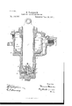
The accompanying drawing illustrates a vertical sectional view of my improved dashpot.
A represents the cylinder'of the dash-pot, and comprises an enlarged chamber a and a smaller or contracted chamberb, the chamber a being closed by an air-tight cap or head 0. In the center of this cap or head 0 a perforated boss or enlargement c is provided, through which the hollow piston-rod E is adapted to pass, said piston-rod being normally closed, as hereinafter set forth, and adapted to pass into the chamber 19 and form a piston for the lower chamber 12. At a point between its ends the piston-rod Eis provided with a piston E, adapted to operate in the chamber a and normally rest upon a ring e of cushioning material located in the bottom of the chamber a, said chamber being cut away to produce a recess a in the interior wall of the cylinder, for a purpose which will be explained further on. The lower. end of the rod E is provided with ahead F, having a central screw-threaded opening f for the reception of a socketed block G, the head F be ing cut away for the accommodation of packing material F, the edge of which is bent under said head and held in place by an annular flange G, projecting from the socket-ed piece G. The head F is so constructed that When the packing material F isin position an annular recess or chamber 1) will be formed above it. Beneath the packing material F the annular flange G of the head F will preferably be provided with openings 0L2. Near the upper end of thesocket G of the block or piece G a perforation h is made at right angles to the socket G2 and adapted to communicate with the hollow rod E. The block G is also provided in its upper end with a perforation, through which a valve-stemj is adapted to pass loosely, the body portion of said stem being made somewhat smaller than the socket G and provided at its lower end with a flange or head K, adapted to normallyproject slightly below the socketed block G, being maintain ed normally in this position by means of a spring L, which encircles the stem and rests at one end against the head K and at the other end against the top wall of the socket G The socket G is preferably enlarged at its lower end for the accommodation of the head K of the valve-stem j and produces a shoulder a 8c A washer a is preferably located on the head K. The stem j is provided withaperforation or duct M, the upper end of which is adapted to remain normally in proximity to the perforation h, and, when the valve-stem isforced upwardly by engagement with the bottom of the chamber 7), to align with said perforation and permit the escape of air from'the bottom of said chamber 1). Holes 0 0 are provided for oiling the lower cylinder and piston and communicate with the annular recess or channel Z) and serves to retain the oil poured into the hollow piston-rod from above and carried into the grooves through the holes 0 0.
Arranged at one side of the dash pot and adapted at its ends to communicate with the cylinder A of the dash-pot is an independent channel or by-pass g, which is adapted to be closed by a screw-plug valve q, said screw plug valve passing through a perforated boss -I0O The operating-wheel g of the valve q is provided with a series of notches for the reception of a spring-plate r, secured to the boss (1 whereby the valve q will be retained in the position in which it is set. Now it will be seen that when the steam-valve of the engine opens and the dash-pot piston rises a vacuum is formed in the lower chamber]; of the dashpot, and as soon as the lower edge of the large cushioning-piston E passes the point x in the chamber a air passes under the piston, as shown by the arrows in Fig. 1. This continues until the upper edge of the piston E reaches the point y, when the air still remaining above the piston will be compressed. If now the dash-pot piston is released,the vacuum under the piston in the smaller chamber 1) and also the compression above the piston E will assist to quickly drop the piston and close the steam-valve B, the air now passing over it in the opposite direction.
In order to prevent excessive resistance under the piston, the by-pass q is provided,
through which the air may pass from under the piston into the cylinder, over the piston, a sufficient amount of air remaining under the piston to afford the requisite cushioning effect. The extent of escape of air from one side of the piston to the other through the bypass q may be regulated by the plug-valve q.
Any air that might accumulate by leakage between the piston or piston-rod and cylinder will find release through the perforation in the valve-stem j and perforation h when said valve-stem is forced by air under the piston to lift.
It is evident that slight changes might be made in the details of construction of my invent-ion without departing from the spirit thereof or limiting its scope. Hence I do not wish to limit myself tothe precise details of construction herein set forth; but,
Having fully described myinvention, what I 3. A dash-pot comprising communicating v cylinders of different diameters, a piston-rod, a piston thereon, a by-pass or independent passage communicating at its ends with the larger cylinder, a wheel carried by said valve and having notches in its periphery, and a spring-plate adapted to engage in said notches to retain the valve in position, substantially as set forth.
4. In a dash-pot, the combination, with a cylinder comprising two chambers, of a 1101- low piston-rod, a piston for each chamber carried by said piston-rod, the smaller piston being provided with a perforation and asocket, a valve-stem in said socket having a duct therein, and a spring adapted to normally maintain the duct in the valve-stem out of alignment with said perforation, anda valved by-pass communicating at its ends with the ends of the larger chamber, substantially as set forth.
In testimony whereof I have signed this specification in the presence of two subscribing witnesses.
HERMAN II'ABERLIN.
\Vitnesses:
W. G. PITKIN, J. G. POPE.
Publications (1)
| Publication Number | Publication Date |
|---|---|
| US465797A true US465797A (en) | 1891-12-22 |
Family
ID=2534661
Family Applications (1)
| Application Number | Title | Priority Date | Filing Date |
|---|---|---|---|
| US465797D Expired - Lifetime US465797A (en) | Herman haberlin |
Country Status (1)
| Country | Link |
|---|---|
| US (1) | US465797A (en) |
-
0
- US US465797D patent/US465797A/en not_active Expired - Lifetime
Similar Documents
| Publication | Publication Date | Title |
|---|---|---|
| US20180135718A1 (en) | Shock absorber | |
| US20180187576A1 (en) | Support element | |
| US2452885A (en) | Hydraulic shock absorber | |
| US671559A (en) | Pneumatic power-cylinder. | |
| US449878A (en) | habeelin | |
| JPS633479Y2 (en) | ||
| US957286A (en) | Piston-valve. | |
| US1195429A (en) | John acton | |
| US940143A (en) | Valve-stem lubricator and packing. | |
| US518026A (en) | Valve device | |
| US730814A (en) | Lubricating device. | |
| US685931A (en) | Valve. | |
| US670795A (en) | Balancing device for engine-valves. | |
| US1226673A (en) | Pneumatic cushioning device. | |
| US825588A (en) | Suction-valve. | |
| US706616A (en) | Governor-valve. | |
| US248728A (en) | Puppet-valve | |
| US1161648A (en) | Drain-cock. | |
| US1018517A (en) | Plunger. | |
| US1319022A (en) | Planooftaph co | |
| US1268270A (en) | Fluid-power hammer. | |
| US334860A (en) | Milan w | |
| US786915A (en) | Pump-governing device. | |
| US626122A (en) | Speed-regulator for explosive-engines | |
| US919513A (en) | Pressure-regulator. |