US465655A - Independent electric clock - Google Patents
Independent electric clock Download PDFInfo
- Publication number
- US465655A US465655A US465655DA US465655A US 465655 A US465655 A US 465655A US 465655D A US465655D A US 465655DA US 465655 A US465655 A US 465655A
- Authority
- US
- United States
- Prior art keywords
- lever
- pendulum
- circuit
- magnet
- armature
- Prior art date
- Legal status (The legal status is an assumption and is not a legal conclusion. Google has not performed a legal analysis and makes no representation as to the accuracy of the status listed.)
- Expired - Lifetime
Links
- 230000010355 oscillation Effects 0.000 description 6
- 239000000725 suspension Substances 0.000 description 6
- 230000000694 effects Effects 0.000 description 4
- 230000035939 shock Effects 0.000 description 3
- 238000010276 construction Methods 0.000 description 2
- 230000004048 modification Effects 0.000 description 2
- 238000012986 modification Methods 0.000 description 2
- 230000000284 resting effect Effects 0.000 description 2
- 230000000717 retained effect Effects 0.000 description 2
- 101100536354 Drosophila melanogaster tant gene Proteins 0.000 description 1
- 230000002950 deficient Effects 0.000 description 1
- 238000010586 diagram Methods 0.000 description 1
- 229940035564 duration Drugs 0.000 description 1
- 230000005484 gravity Effects 0.000 description 1
- 238000000034 method Methods 0.000 description 1
- 230000003534 oscillatory effect Effects 0.000 description 1
- 230000010287 polarization Effects 0.000 description 1
- 230000000630 rising effect Effects 0.000 description 1
- 239000007787 solid Substances 0.000 description 1
Images
Classifications
-
- G—PHYSICS
- G04—HOROLOGY
- G04C—ELECTROMECHANICAL CLOCKS OR WATCHES
- G04C3/00—Electromechanical clocks or watches independent of other time-pieces and in which the movement is maintained by electric means
- G04C3/02—Electromechanical clocks or watches independent of other time-pieces and in which the movement is maintained by electric means wherein movement is regulated by a pendulum
- G04C3/021—Electromechanical clocks or watches independent of other time-pieces and in which the movement is maintained by electric means wherein movement is regulated by a pendulum using mechanical coupling
- G04C3/022—Electromechanical clocks or watches independent of other time-pieces and in which the movement is maintained by electric means wherein movement is regulated by a pendulum using mechanical coupling with constant impulses
Definitions
- Myinvention relates to an electric clock of that class in which a time-measurin g vibrator, preferably a pendulum, controls in its vibrations the circuit of an electro-magnet, which in turn actuates an impelling device that imparts to the vibrator an impulse suflicient to counteract the resistance to its vibratory movement, and thus maintain its oscillatory motion.
- a time-measurin g vibrator preferably a pendulum
- the present invention is shown embodied in a clock having a pendulum to measure the time and a gravitating impelling device; and the invention consists, mainly, in details of the construction of the impelling device and the means for supporting it when raised by the electro-magnct, and for disengaging it from its support, so that its weight is applied to the pendulum to give it the impulse; in the means for controlling the circuit of the electro-magnet by which the impelling device is raised at ter theimpulse has been given byit,preparatory for giving the nextimpulse; in the means used to actuate the train by which the hands of the clock are moved, so that an occasional failure of contact will not affect the indicating part of the clock, and in the form and arrangement of the electro-magnet and armature relatively to the impelling device.
- the devices co-operating with the pendulum comprise two levers pivoted near the center of oscillation of the pendulum and each having a projection that engages with one side of the pendulum-rod, these devices resembling in their relation to the pendulum-rod the crutch commonly used in spring or weight driven clocks, except that each engages the pendulum-rod at one side only.
- Both of the pivoted levers are weighted,so as to causethe projections carried by them to bear against the pendulum-rod, tending to give an impulse to the same; but one of them bears against the rod both as the latter moves toward and from it, so that its effect, so far as impelling the rod is concerned, is nothing.
- the other of said levers constitutes the impelling device, and it is raised independently of the pendulum and while disengaged therefrom, and is in engagement with the pendulum only while the latter is moving away from it, so that the force of gravity on the impelling device is added as an impulse to the pendulum and is sufficient to counteract the resistance to the movement of the pendulum, so as to maintain it in substantially uniform oscillation.
- Said lever also co-operates with the circuit-closing devices to limit the duration of the closure of circuit to the time actually required to raise said lever to its highest point, being arranged to break the circuit when :l' ully so raised.
- the first mentioned lever which engages with the pendulum both in the rising and falling movement, operates the circuit-closer for an electro-magnet, the armature of which raises the impelling-lever, and said first-mentioned or circuit-controlling lever also co-operates v with a detent for the impelling-lever, which detent supports the latter while the pendulum is completing its vibration away from it after the impulse has been given and while the pendulum is making practically its whole vibration toward the said impelling-lever, at the end of which the said detent is disengaged by the conjoint action of the pendulum-rod and the circuit-closing lever at the other side thereof.
- Said first-mentioned or circuit-closing lever also actuates the train of wheels which moves the hands of the clock by means of a click or pawl preferably pivoted on one extremity of a bell-crank lever which is used to transmit the motion of the circuit-closing lever to the detent for the impelling-lever, said click or pawl actuating a ratchet-wheel forming part of said train of wheels step by step at each vibration of the pendulum.
- the impelling-lever and the circuit-closing lever both accompany the pendulum-rod about to the middle point of its oscillation and are there arrested, so that the pendulum-rod co-operates with one of the pivoted levers while at one side of the middle point of its oscillation and with the other while at the other side of its middle point of oscillation and as the movement of the bellcrank lever and attached click or pawl which actuate the hands of the clock caused by the weight of the circuit-closing lever can only'take place when the pendulum-rod has engaged the impelling-lever and released it from its detent, and therefore when said pendulum-rod is out of engagement with said circuit-closing lever the inequalities of the train of wheels do not practically affect the pendulum.
- the armature of the electro-magnet.which raises the impelling device is of special form and pivoted at its center between the poles of said electro-magnet, which is of the ordinary double branched variety, so that said armature is turned upon its center by the attraction of the magnet. This is done to secure a large angular movement of said armature with maximum power, combined with lightness of moving parts and absence of strain on pivots; also, to bring the pivotal points of the armature and impelling-lever as near together as possible to avoid rubbing friction in transmitting the motion of the armature to the impelling-lever.
- the impelling-lever can only engage the circuit-closing spring when the former is near its raised position orlocking-point, and will then break the circuit and keep it broken so long as it is held in this raised position, which it will be by its detent until released by the action of the pendulumrod, when after a slight movement in the direction toward which said impelling-lever moves in giving impulse to the pendulum it releases said circuit-closer, which would immediately close the circuit and thereby prevent the further movement of said impellinglever. Said circuit-closer is now engaged by the circuit-closing lever, which latter is now at its lowest position and the circuit-closer is thereby prevented from engaging with its stationary member until the impelling device has given its full impulse to the pendulum and reached its lowest position.
- the pendulum-rod will have engaged the circuit-closing lever and raised it, thereby permitting the circuit-closer to close the circuit, which will remain closed long enough for the action of the electro-magnet to raise the impelling-lever nearly to its raised or looking position, when said lever will engage with the circuit-closer and break the circuit.
- the action of the electro-magnet will then cease; but the acquired momentum of the impelling-lever will be sufficient to carry it past the locking-point with the circuit broken.
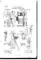
- Figure 1 is a front elevation of the operative parts of an electric clock embodying this invention, the face and hands of the clock and gearing immediately connected with the hands being removed.
- Fig. 2 is a side elevation as viewed from the left of Fig. 1.
- Figs. 1 and 5 are detached and enlarged elevations of the escapement or parts immediately eonnected with the pendulum, viewed from the front as in Fig. 1.
- Fig. 3 is a detached elevation of part of the circuit-controlling devices, viewed from the right of Fig. 4.
- Figs. 6 and 7 are detached elevations of modifications of parts of the escapement.
- Fig. 8 is a view of a modification of the circuit-controlling devices.
- the rod (6 of the pendulum, which latter is not shown, may be hung to oscillate about a support at a in the usual manner, the said rod being broken away in places to show parts beneath.
- Rod ct is between projecting fingers b c of levers b c, which are pivoted at b c near the center of suspension of the pendulum, said levers each being supported on a rock-shaft having its bearings in the main frame-plates A A that support the working parts of the clock-movement, front plate A having a projecting cock C to receive the front ends of said rock-shafts.
- pendulum is intended to include any time-measuring vibrator.
- Levers b and 0 have weighted lateral arms 13 c, which tend to turn said levers on their pivots in such direction as to move the pendulum-engaging fingers b 0 toward the pendulum-rod.
- the lever c with its weighted arm c ,is the impelling device, and is further provided with an arm 0 and projecting pin 0 to control the circuit-closer for the electro-magnet e, as hereinafter described.
- Lever Z) operates the circuit-closer for electro-magnet e, by which the impelling device is raised, and will be hereinafter called the circuit-closing 'lever althou h it also imnels the hands of the clock and performs otherfunctions, which will be hereinafter described.
- the circuit-closing lever 11 operates a contact-spring f, constituting one member of a circuit-closer and arranged to engage by its own resiliency the stationary member f which is supported by an insulated post f, said members controlling the circuit of the electro-inagnet c, said circuit being indicated in diagram in Fig. 1, and includes the battery B, by which said magnet is energized, said spring being also operated by impelling-lever c to break the circuit when said lever is raised to its highest point.
- Contact-spring f has one end rigidly secured at f to plate A, while near its other end it is provided with a contact-plate f which when said spring is unconstrained rests against the other member f secured to and insulated from plate A, as shown, the cont-act of said plate with member f closing a circuit comprising a battery 13, frame A A of the clock, and the coils of electro-magnet 6, thereby energizing said magnet.
- the pivoted portions of the levers b and care rock-shafts having theirbearings in the frameplates A A while their lower ends engage with pen dnl uni-rod 0.
- Electro-magnet e which is of the ordinary double-branched form, is placed between the plates A A of the clock, its cores passing through both of said plates, as shown in Figs. 1 and 2. Said cores are joined behind the back plate A by a yoke of the usual form, while the other ends of said cores project a little beyond the front plate A, as shown in Figs. 1 and 2. Said magnet is thus firmly secured in place.
- the amature 7c of electro-magnet e which is best shown in Fig. 1, is pivoted in front of plate A, one of its pivots being in the same cock 0 of plate A as the pivots of levers b and c, and as near them as possible the other pivot of said armature is in plate A
- the pivotal point of said armature 7.: is also in the middle of a straight line joining the centers of the projecting ends 6 of the cores of magnet 6, so that the attraction of the poles of said magnet acts as a couple to turn said armature on its pivots W, said armature being shaped as shown in Fig.
- a pin 70 fixed in one end of armature 7t, projects forward beneath weighted arm 0 of impulse-lever c and in such relation thereto that when said armature is attracted said pin engages with and raises said arm and forces said lever c to the left in Fig. 1 until said lever is in position to be retained so raised by a catch (1, pivoted at (1 and with a hooked end d said hooked end engaging an elastic projection 0 secured to lever c, as shown in Fig. l.
- Detent (Z is by its own weight normally kept in the position shown in full lines in Fig. 4, but is momentarily lifted into the position shown in dotted lines by the end 0 of the elastic projection of lever c, sliding along theinclined face of said detent when said lever c is being raised into the locking position by magnet c.
- Lever b by its finger b engages the pendulum-rod both while the pendulum is moving to the right in Fig. 1, so as to close the contacts ff and while the pendulum is making the first part of its return movement to the left, the weight of said lever and its weighted arm 11 tending to accelerate the pendulum as much in its return movement as they tended to retard it in its movement to the right, and the finger 1) follows the pondulum-rod in its return movement until said finger engages vertical arm 9 of a bell-crank lever g, pivoted at g" and having a horizontal arm weight-ed so as to normally keep the vertical arm g against a stop-pin g, secured in the front plate A of the clock.
- the horizontal arm 9 of the bell-crank extends to the left in Figs. 1, 1, and 5, and passesimmediatelybeneath a pin (Z secured in the free end of detent (Z, said pin (Z forming a stop to limit the downward movementof detentd, the downward movement of thehorizontal arm 9 of the bell-crank on which said pin rests being limited by the vertical arm g engaging pin g.
- Lever l is snfficiently weighted to overcome the weights of detentd and thehorizontal arm g of the bell-crank if they are otherwise uncontrolled, but is not sufficient to overcome the resistance of impulselever c, which is at this time by its projection c lockinginto said detent, both said detent and projection being formed with a certain amount of hook or draw, both to render the locking securer and to prevent the shock of the contact of lever 1) with arm 9 of the bell-crank from unlocking said impulse arm.
- Pendulum-rod a continues its motion to the right independently of lever 0, until said rod again engages with finger I) of lever Z), the position of parts being at this time as in Fig. 4, and moves said lever into the dotted position in said figure, permitting the horizontal arm of the bell-crank g and also detent cl to drop down ready to support impulse-lever 0 when raised, which is done when contact-spring j", which follows the motion of lever 1), makes contact with stationary member f thereby closing the circuit of and engaging electromagnet e, the latter attracting armature 7c, and thereby raising lever c, said lever again breaking the contact between spring f and fixed member-f by engaging the same with pin 0 in arm 0 of said lever, the required momentum, however, carrying said lever beyond its locking position with detent d, so that it is supported thereby with the circuit of magnet 6 broken, as hereinbefore explained.
- the time thus measured by the beats of the pendulum is indicated by a clockdial and hands inany usual manner, the said hands being turned by a train of wheel-work t i '2'", the shaft of which latter wheel is provided with a ratchet-wheel r, engaged by a click or pawl m, pivoted at m near the extremity of horizontal arm of bell-crank g, said click or pawl engaging with the teeth of ratchet-wheel 1', said ratchet-wheel being pivoted as near as possible to the pivotal point of bell-crank g.
- a pin b secured in lever b is arranged to engage either with detentpawl r or the periphery of said ratchet-wheel, and thereby arrest the motion of said lever and ratchet-wheel simultaneously as soon as click on has moved said wheel one tooth, thereby preventing any further motion of said wheel, said pin 11 serving both to prevent the skippingof ratchet-wheel rand. as a banking or step-pin for lever 12.
- contact-spring f may also be secured to lever b, as at f, Fig. 6, instead of to frame-plate A, otherwise operating as hereinbefore described, and this may in some cases be a preferable construction.
- the driving-click m instead of being pivoted to bell-crank g, may be replaced by click m Fig.
- the detent-p:.twl 0' may be placed in such relation to click m that said click rides over said dctent-pawl when said click is drawn back beyond one tooth of wheel 1, as shown by full and dotted lines in Fig. 7; or a projection m Fig. (5, of frame-plate A of the clock may raise click at outof engagementwith wheel r when said click is drawn back too far, and detent (Z may be dispensed with in this arrangement, bell crank g serving also as a detent for impulselever c, as shown in Fig.
- a doublewound resistance-coil s is arranged as a shunt or branch circuit around the coils of magnet e, the resistance of said coilbeing adjusted to prevent sparking in the circuitcloser in a well-known manner.
- said pendulum-rod may engage the circuitcloser directly without the intervention of said lever, as in Fig. 8, pendulum-rod a closi ng the circuit and impelling-lever c breaking the circuit when raised by the eleetro-magnet, as hereinbefore described.
- the devices for controlling the circuit of the electro-magnet and battery are of great value, for it is necessary to reduce the dura tion of closure of circuit as much as possible, both because the battery thereby lasts longer and its polarization is greatly lessened.
- I claim- 1 The combination of the time-measuring vibrator, its impelling device and restoring electro-magnet and armature therefor, a second lever independent of said impelling device pivoted near the center of suspension of and engaged by said tim e-measu ring vibrator, and a circuit-closer for said electro-magnet independent of but normally jointly controlled by said impelling device and secondlever, substantially as described.
Landscapes
- Physics & Mathematics (AREA)
- General Physics & Mathematics (AREA)
- Magnetic Treatment Devices (AREA)
Description
(No Model.)
W. J. DUDLEY.
INDEPENDENT ELECTRIC CLOCK.
No. 465,655. Patented Dec. 22, 1891.
WITNEI 55:5.
UNITED STATES PATENT OEEIcE.
\VALTER J. DUDLEY, OF SOT-\IERVILLE, MASSAOHUSET' INDEPENDENT ELECTRIC CLOCK.
SPECIFICATION forming part cf Letters Patent No. 465,655, dated December 22, 1891.
Application filed July 11, 1891. Serial No. 399,249. (No model.)
To all whazn it may concern:
Be it known that I, WALTER J .DUDLEY, of Somerville, in the county of Middlesex and State of Massachusetts, have invented a new and usefullmprovement in Independent Electric Clocks, of which the following, taken in connection with the accompanying drawings, is a specificatiomlike letters on the drawings representing like parts.
Myinvention relates to an electric clock of that class in which a time-measurin g vibrator, preferably a pendulum, controls in its vibrations the circuit of an electro-magnet, which in turn actuates an impelling device that imparts to the vibrator an impulse suflicient to counteract the resistance to its vibratory movement, and thus maintain its oscillatory motion.
The present invention is shown embodied in a clock having a pendulum to measure the time and a gravitating impelling device; and the invention consists, mainly, in details of the construction of the impelling device and the means for supporting it when raised by the electro-magnct, and for disengaging it from its support, so that its weight is applied to the pendulum to give it the impulse; in the means for controlling the circuit of the electro-magnet by which the impelling device is raised at ter theimpulse has been given byit,preparatory for giving the nextimpulse; in the means used to actuate the train by which the hands of the clock are moved, so that an occasional failure of contact will not affect the indicating part of the clock, and in the form and arrangement of the electro-magnet and armature relatively to the impelling device. The devices co-operating with the pendulum comprise two levers pivoted near the center of oscillation of the pendulum and each having a projection that engages with one side of the pendulum-rod, these devices resembling in their relation to the pendulum-rod the crutch commonly used in spring or weight driven clocks, except that each engages the pendulum-rod at one side only. Both of the pivoted levers are weighted,so as to causethe projections carried by them to bear against the pendulum-rod, tending to give an impulse to the same; but one of them bears against the rod both as the latter moves toward and from it, so that its effect, so far as impelling the rod is concerned, is nothing. The other of said levers constitutes the impelling device, and it is raised independently of the pendulum and while disengaged therefrom, and is in engagement with the pendulum only while the latter is moving away from it, so that the force of gravity on the impelling device is added as an impulse to the pendulum and is sufficient to counteract the resistance to the movement of the pendulum, so as to maintain it in substantially uniform oscillation. Said lever also co-operates with the circuit-closing devices to limit the duration of the closure of circuit to the time actually required to raise said lever to its highest point, being arranged to break the circuit when :l' ully so raised. The first mentioned lever, which engages with the pendulum both in the rising and falling movement, operates the circuit-closer for an electro-magnet, the armature of which raises the impelling-lever, and said first-mentioned or circuit-controlling lever also co-operates v with a detent for the impelling-lever, which detent supports the latter while the pendulum is completing its vibration away from it after the impulse has been given and while the pendulum is making practically its whole vibration toward the said impelling-lever, at the end of which the said detent is disengaged by the conjoint action of the pendulum-rod and the circuit-closing lever at the other side thereof. Said first-mentioned or circuit-closing lever also actuates the train of wheels which moves the hands of the clock by means of a click or pawl preferably pivoted on one extremity of a bell-crank lever which is used to transmit the motion of the circuit-closing lever to the detent for the impelling-lever, said click or pawl actuating a ratchet-wheel forming part of said train of wheels step by step at each vibration of the pendulum. The impelling-lever and the circuit-closing lever both accompany the pendulum-rod about to the middle point of its oscillation and are there arrested, so that the pendulum-rod co-operates with one of the pivoted levers while at one side of the middle point of its oscillation and with the other while at the other side of its middle point of oscillation and as the movement of the bellcrank lever and attached click or pawl which actuate the hands of the clock caused by the weight of the circuit-closing lever can only'take place when the pendulum-rod has engaged the impelling-lever and released it from its detent, and therefore when said pendulum-rod is out of engagement with said circuit-closing lever the inequalities of the train of wheels do not practically affect the pendulum.
The armature of the electro-magnet.which raises the impelling device is of special form and pivoted at its center between the poles of said electro-magnet, which is of the ordinary double branched variety, so that said armature is turned upon its center by the attraction of the magnet. This is done to secure a large angular movement of said armature with maximum power, combined with lightness of moving parts and absence of strain on pivots; also, to bring the pivotal points of the armature and impelling-lever as near together as possible to avoid rubbing friction in transmitting the motion of the armature to the impelling-lever. The circuitcloser-here a flat spring or pivoted lever carrying a contact point or points and cooperating with a stationary contact-point by its own resiliencyis controlled by both the impelling and circuit-closing levers, and when either of said' levers engages with the free end of said spring the circuit of the electromagnet is broken. The impelling-lever can only engage the circuit-closing spring when the former is near its raised position orlocking-point, and will then break the circuit and keep it broken so long as it is held in this raised position, which it will be by its detent until released by the action of the pendulumrod, when after a slight movement in the direction toward which said impelling-lever moves in giving impulse to the pendulum it releases said circuit-closer, which would immediately close the circuit and thereby prevent the further movement of said impellinglever. Said circuit-closer is now engaged by the circuit-closing lever, which latter is now at its lowest position and the circuit-closer is thereby prevented from engaging with its stationary member until the impelling device has given its full impulse to the pendulum and reached its lowest position. At this time the pendulum-rod will have engaged the circuit-closing lever and raised it, thereby permitting the circuit-closer to close the circuit, which will remain closed long enough for the action of the electro-magnet to raise the impelling-lever nearly to its raised or looking position, when said lever will engage with the circuit-closer and break the circuit. The action of the electro-magnet will then cease; but the acquired momentum of the impelling-lever will be sufficient to carry it past the locking-point with the circuit broken.
Figure 1 is a front elevation of the operative parts of an electric clock embodying this invention, the face and hands of the clock and gearing immediately connected with the hands being removed. Fig. 2 isa side elevation as viewed from the left of Fig. 1. Figs. 1 and 5 are detached and enlarged elevations of the escapement or parts immediately eonnected with the pendulum, viewed from the front as in Fig. 1. Fig. 3 is a detached elevation of part of the circuit-controlling devices, viewed from the right of Fig. 4. Figs. 6 and 7 are detached elevations of modifications of parts of the escapement. Fig. 8 is a view of a modification of the circuit-controlling devices.
The rod (6 of the pendulum, which latter is not shown, may be hung to oscillate about a support at a in the usual manner, the said rod being broken away in places to show parts beneath. Rod ct is between projecting fingers b c of levers b c, which are pivoted at b c near the center of suspension of the pendulum, said levers each being supported on a rock-shaft having its bearings in the main frame-plates A A that support the working parts of the clock-movement, front plate A having a projecting cock C to receive the front ends of said rock-shafts.
The term pendulum is intended to include any time-measuring vibrator.
Levers b and 0 have weighted lateral arms 13 c, which tend to turn said levers on their pivots in such direction as to move the pendulum-engaging fingers b 0 toward the pendulum-rod. The lever c, with its weighted arm c ,is the impelling device, and is further provided with an arm 0 and projecting pin 0 to control the circuit-closer for the electro-magnet e, as hereinafter described. Lever Z) operates the circuit-closer for electro-magnet e, by which the impelling device is raised, and will be hereinafter called the circuit-closing 'lever althou h it also imnels the hands of the clock and performs otherfunctions, which will be hereinafter described.
The circuit-closing lever 11 operates a contact-spring f, constituting one member of a circuit-closer and arranged to engage by its own resiliency the stationary member f which is supported by an insulated post f, said members controlling the circuit of the electro-inagnet c, said circuit being indicated in diagram in Fig. 1, and includes the battery B, by which said magnet is energized, said spring being also operated by impelling-lever c to break the circuit when said lever is raised to its highest point. Contact-spring f has one end rigidly secured at f to plate A, while near its other end it is provided with a contact-plate f which when said spring is unconstrained rests against the other member f secured to and insulated from plate A, as shown, the cont-act of said plate with member f closing a circuit comprising a battery 13, frame A A of the clock, and the coils of electro-magnet 6, thereby energizing said magnet. The pivoted portions of the levers b and care rock-shafts having theirbearings in the frameplates A A while their lower ends engage with pen dnl uni-rod 0. by the projecting fingers b 0 as hereinbefore described, the motion of said levers b and 0 being limited, as will be hereinafter explained, so that each follows said pendulum-rod down to about the vertical or middle position of said rod, so that each lever partakes of thejmotion of said rod during the time said rod is on that side of its middle position on which such lever lies. I-mpulse-lever c engages the free end of contactspringf by means of a pin 0, fixed in an arm 0 of said lever in such manner that when said lever is raised to its highest position or to the locking-point by the action of electro-magnet c said pin 0 forces said spring f away from its contact f and in this position the circuit of the electro-magnet is broken and any motion of circuit-closing lever b will not affect spring f. A pin 17, secured to lever I), also engages with the free end of contact-spring f in such manner as to force it away from its contact f at all times, except when said lever is raised to nearly its highest position, which occurs when the pendulum has swung to nearly the full extent of its motion. to the right in Figs. 1, 4, 5, and 6. Thus the circuit of magnet e and its energizing-battery B can only be closed when impulse-lever c is at its lowest point and circuit-closing lever b at nearly its highest position, or when the pendulum of the clock has swung to the right, Fig. 1, after receiving impulse from impulselever c.
Electro-magnet e, which is of the ordinary double-branched form, is placed between the plates A A of the clock, its cores passing through both of said plates, as shown in Figs. 1 and 2. Said cores are joined behind the back plate A by a yoke of the usual form, while the other ends of said cores project a little beyond the front plate A, as shown in Figs. 1 and 2. Said magnet is thus firmly secured in place.
The amature 7c of electro-magnet e, which is best shown in Fig. 1, is pivoted in front of plate A, one of its pivots being in the same cock 0 of plate A as the pivots of levers b and c, and as near them as possible the other pivot of said armature is in plate A The pivotal point of said armature 7.: is also in the middle of a straight line joining the centers of the projecting ends 6 of the cores of magnet 6, so that the attraction of the poles of said magnet acts as a couple to turn said armature on its pivots W, said armature being shaped as shown in Fig. 1, with its ends k formed to partially surround said poles to more efficiently utilize the magnetic force of said magnet, especially when said armature is farthest from said magnet. The normal unattracted position of armature Is, it being weighted to fall away from poles 6 is shown in full lines in Fig. 1, while the position it assumes when fully attracted is shown by dotted lines in said figure. The extent of movement of the ends k of armature 7t from poles e of magnet is adjusted by a stopscrew 19, threaded in a projection 13 of front plate A, against which one end of said armature strikes, as shown. A pin 70, fixed in one end of armature 7t, projects forward beneath weighted arm 0 of impulse-lever c and in such relation thereto that when said armature is attracted said pin engages with and raises said arm and forces said lever c to the left in Fig. 1 until said lever is in position to be retained so raised by a catch (1, pivoted at (1 and with a hooked end d said hooked end engaging an elastic projection 0 secured to lever c, as shown in Fig. l. Detent (Z is by its own weight normally kept in the position shown in full lines in Fig. 4, but is momentarily lifted into the position shown in dotted lines by the end 0 of the elastic projection of lever c, sliding along theinclined face of said detent when said lever c is being raised into the locking position by magnet c.
Lever b, by its finger b engages the pendulum-rod both while the pendulum is moving to the right in Fig. 1, so as to close the contacts ff and while the pendulum is making the first part of its return movement to the left, the weight of said lever and its weighted arm 11 tending to accelerate the pendulum as much in its return movement as they tended to retard it in its movement to the right, and the finger 1) follows the pondulum-rod in its return movement until said finger engages vertical arm 9 of a bell-crank lever g, pivoted at g" and having a horizontal arm weight-ed so as to normally keep the vertical arm g against a stop-pin g, secured in the front plate A of the clock. The horizontal arm 9 of the bell-crank extends to the left in Figs. 1, 1, and 5, and passesimmediatelybeneath a pin (Z secured in the free end of detent (Z, said pin (Z forming a stop to limit the downward movementof detentd, the downward movement of thehorizontal arm 9 of the bell-crank on which said pin rests being limited by the vertical arm g engaging pin g. Lever l) is snfficiently weighted to overcome the weights of detentd and thehorizontal arm g of the bell-crank if they are otherwise uncontrolled, but is not sufficient to overcome the resistance of impulselever c, which is at this time by its projection c lockinginto said detent, both said detent and projection being formed with a certain amount of hook or draw, both to render the locking securer and to prevent the shock of the contact of lever 1) with arm 9 of the bell-crank from unlocking said impulse arm. The object of making the locking projection c on lever c yielding or elastic is to prevent the shock and noise which, were said projection solid, would be caused by said lever 0 being carried past the lockingpointby electro-magnet e and then falling back suddenly against the hook of detent (1. Elastic projection c is secured to lever 0 at c and is made thin and long enough to bring about the desired effect. Lever b,
therefore, having followed the pendulum-rod in its return movement to the left, stops with its finger b resting against vertical arm 1 of the belhcrank g, ready to move said bellcrank and raise detent (Z when the latter is released from its locking with impulse-arm 0, while the pendulum continues its movement to the left independently of said lever, the position of parts at this time being shown in Fig. 1, in which a part of lever c is broken away to show the parts behind it.
\Vhen the pendulum-rod a nears the end.
of its motion to the left, it engages the finger c of lever c, and moves'said lever to the left, thus releasing the projection c from its looking with detent (1, under which conditions the weight of lever 12, acting directly on bell-crank g and thus indirectly on said detent d, raises the latter, the position of said parts being at this time as shown in Fig. 5, in which figure the pendulum has reached the limit of its movement to the left and is about to move to the right again. The weight of arm 0 is now pressing impulse-lever 0 against pendulumrod a, and as detent (Z is now raised out of the path of projection c said lever 0 follows the pendulum-rod until arm 0 of said lever engages pin 7& of armature 7t, and thereby arrests the motion of said lever, it having imparted sufficient impulse tothe pendulum, and being new in position to be again raised to the locking-point by said armature, and 'also having moved pin 0 so far out of engagement with contact-spring f that the latter is now resting against pin b in lever b, and said spring is now controlled by said lever Z). Pendulum-rod a continues its motion to the right independently of lever 0, until said rod again engages with finger I) of lever Z), the position of parts being at this time as in Fig. 4, and moves said lever into the dotted position in said figure, permitting the horizontal arm of the bell-crank g and also detent cl to drop down ready to support impulse-lever 0 when raised, which is done when contact-spring j", which follows the motion of lever 1), makes contact with stationary member f thereby closing the circuit of and engaging electromagnet e, the latter attracting armature 7c, and thereby raising lever c, said lever again breaking the contact between spring f and fixed member-f by engaging the same with pin 0 in arm 0 of said lever, the required momentum, however, carrying said lever beyond its locking position with detent d, so that it is supported thereby with the circuit of magnet 6 broken, as hereinbefore explained. By this co-operation between levers b and c and contact-spring f the closure of the circuit is limited to the time actually necessary to raise and lock lever c, and a great economy is realized over the ordinary methods of controllingthe circuits ofindependentelectric clocks, and the adjustments may be made once for all and will not be affected by any change in the are of the pendulum. The fixed member f of the circuit-closer is adjustable relatively to springf, being a screw threaded in a post f in which said screw turns stiifly, said post I being secured to but insulated from frameplate A. In this manner the pendulum is retained in vibration so long as the batter-yenergizes the magnet sufliciently to raise the impelling-lever. The time thus measured by the beats of the pendulum is indicated bya clockdial and hands inany usual manner, the said hands being turned by a train of wheel-work t i '2'", the shaft of which latter wheel is provided with a ratchet-wheel r, engaged by a click or pawl m, pivoted at m near the extremity of horizontal arm of bell-crank g, said click or pawl engaging with the teeth of ratchet-wheel 1', said ratchet-wheel being pivoted as near as possible to the pivotal point of bell-crank g. Click on advances ratchetwheel r one tooth each time that lever Z) actuates said bell-crank, and being drawn back ready to engage another tooth of the ratchetwheel when said lever is moved out of engagement with said bell-crank, said ratchetwheel being restrained from moving backward by a detent r pivoted to frame-plate A of the clock.
The parts are so adjusted that click on does not move ratchet-"wheel 9" until pendulum-rod a has moved out of engagement with lever l) and engaged with lever 0. Consequently all inequalities in the force required to move the hands of the clock or train errors can effeet the pendulum only through the variations in the force required to unlock lever c from detent (Z, and as the unlocking friction here is at most Very slight such variations are of no practical importance; but if lever 12 were to impel ratchet-wheel 7" while said lever was moving in engagement with and therefore practically a part of the pendulum any train-errors in the wheels connected with the moving hands of the clock would seriously effect the pendulum.
To prevent click on from moving ratchet wheel 1' more than one tooth, which it is apt to do unless prevented, as the motion of hellcrank g is quite rapid, and therefore ratchetwheel o might by its acquired momentum be carried by a tooth, a pin b secured in lever b, is arranged to engage either with detentpawl r or the periphery of said ratchet-wheel, and thereby arrest the motion of said lever and ratchet-wheel simultaneously as soon as click on has moved said wheel one tooth, thereby preventing any further motion of said wheel, said pin 11 serving both to prevent the skippingof ratchet-wheel rand. as a banking or step-pin for lever 12.
\Vhile the above-described arrangement and adjustment of the parts connected with the pendulum are believed to be preferable, such arrangement and adjustment may be varied without departing from the principle of my invention. For example, contact-spring f may also be secured to lever b, as at f, Fig. 6, instead of to frame-plate A, otherwise operating as hereinbefore described, and this may in some cases be a preferable construction. The driving-click m, instead of being pivoted to bell-crank g, may be replaced by click m Fig. 6, pivoted directly to lever l) and engaging ratchet-wheel r, as before, and to prevent said click from moving said wheel more than one tooth in case said click were drawn back too far by lever bthe detent-p:.twl 0' may be placed in such relation to click m that said click rides over said dctent-pawl when said click is drawn back beyond one tooth of wheel 1, as shown by full and dotted lines in Fig. 7; or a projection m Fig. (5, of frame-plate A of the clock may raise click at outof engagementwith wheel r when said click is drawn back too far, and detent (Z may be dispensed with in this arrangement, bell crank g serving also as a detent for impulselever c, as shown in Fig. 6 and described and claimed in my patent for independent electric clock, No. H2105. Stop-screwp, by varying the distance armature moves away from the poles e of magnet 6, also varies the distance through which lever 0 follows pendulum-rod a, and therefore by turning said screw the impulse given to the pendulum may be graduated with great accuracy. A doublewound resistance-coil s, Fig. 2, is arranged as a shunt or branch circuit around the coils of magnet e, the resistance of said coilbeing adjusted to prevent sparking in the circuitcloser in a well-known manner.
The form and arrangement of armature relatively to magnet e and lever c is impor-- tant,'as the maximum magnetic et'ficiency' combined with minimum weight of moving parts and avoidance of strain on the pivots of said armature is secured by this arrangement of the armature, and, what in a clock is verydesirable, there is very littie noise, while by placing the pivotal point of said armature as near as possible to that of lever c the force of said armature is exerted on said lever with but slight loss through rubbing friction between said lever and pin 70" in said armature. As lever I) while engaging with the circuitcloser f f is moving with and for this purpose practically a part of pendulum-rod a,
. said pendulum-rod may engage the circuitcloser directly without the intervention of said lever, as in Fig. 8, pendulum-rod a closi ng the circuit and impelling-lever c breaking the circuit when raised by the eleetro-magnet, as hereinbefore described.
The devices for controlling the circuit of the electro-magnet and battery are of great value, for it is necessary to reduce the dura tion of closure of circuit as much as possible, both because the battery thereby lasts longer and its polarization is greatly lessened.
The arrangement of click on or its equivalent m and co-operatin g parts actuating ratchet-wheel r is such that an occasional failure of circuit-closerff to close the circuit of the magnet will not perceptibly affect the hands of the clock, as the pendulum will in such event continue to actuate said hands fora considerable time, and the only effect of occasional defective contacts in the circuitcloser will be a slight falling off of the arc of the pendulum, which would not perceptibly aitect the rate of the clock, whereas if the hands of the clock were moved by a click actuated directly by thearmature of the electromagnet, as is usual, each failure of contact would cause the clock to lose an amount of time equal to one complete oscillation of the pendulum.
I claim- 1. The combination of the time-measuring vibrator, its impelling device and restoring electro-magnet and armature therefor, a second lever independent of said impelling device pivoted near the center of suspension of and engaged by said tim e-measu ring vibrator, and a circuit-closer for said electro-magnet independent of but normally jointly controlled by said impelling device and secondlever, substantially as described.
2. The combination of the pendulum-impelling device, the actuating electro-magnet therefor, and the armature for raising said impelling device pivoted near the axis of said device, said armature being centrally pivoted between the poles of said electro-magnet, so that the attraction of said poles acts as a couple to turn said armature upon its center and thereby raise said impelling device, substantially as described.
3. The combination of the pendulum-impelling device and its actuating electro-niagnet and armature, a detent for supporting said impelling device, a co-operating lever pivoted near the center of suspension of the pendulum and engaged by said pendulum, and a second or intermediate lever through which said first lever co-operates with said detent, substantially as described.
4. The combination of the pendulun1impelling device and actuating electro-magnetand armature therefor, a detent for supporting said impelling device, and the elastic projection of said impelling device engaging with said dctent for the purpose of lessening the shock and noise, substantially as described.
5. The combination of the pendulum-impelling device, its restoring electro-magnet and armature therefor and detent for retaining it when so restored, the train of wheelwork and actuating ratchetwheel thereof, the lever pivoted independently of the impelling device near the center of suspension of the pendulum, and the click or pawl mechanically actuated by said lever to impel said ratchet-wheel, substantially as described.
6. The combination of the time-measuring vibrator, its impelling device and restoring electro-magnet, the armature actuated by said electro-magnet and engaging with said impelling device both to restore it to its highest position and to form a stop for it in its lowest position, and an adjustable stop controlling the extent of motion of both said armature and said impelling device, substantially as described.
7. The combination of the pendulum-impelling device and its restoring electro-magnet and armature, the lever pivoted independently of the impelling device near the center of suspension of the pendulum, the click or pawl actuated by said lever and impellin g a ratchet-wheel and train of wheel-work connected therewith, and a projection of said lever engaging with said ratchet-wheel and simultaneously arresting the motion of said lever and ratchet-wheel, substantially as described.
8. The combination of the time-measuring vibrator and its impelling device and actuating electro-magnet and armature therefor, a detent orlatch forsupporting said device, and a circuit-controlling device for said electromagnet independent of said time-measuring vibrator and impelling device, comprising a fixed and a movable member, the movable member arranged to be engaged by said impelling device when in its raised or latched position, and thereby break the circuit of and to be controlled by said time-measuring vi brator to close the circuit of said electro-magnet when said impelling device is in its lowest position, substantially as described.
9. The combination of the time-measuring vibrator and its impelling device, the actuating electro-magnet with its projecting poles,
and the armature for said electro-magnet centrally pivoted between and turning in a plane at a right angle to the axes of said poles and engaging with said impelling device and with its extremities shaped to partially encircle said poles, substantially as described.
10. The combination of the time-measuring vibrator, its impelling device, and actuating electro magnet and armature therefor, the circuit-closer for said electro-magnet independent of said impelling device, comprising a fixed and a movable member, and a lever pivoted independently of said impelling device, and said circuit-closer engaged by and cooperating with said time-measuring vibrator and with the movable member of said circuit-closer, substantially as described.
11. The combination of the time-measuring vibrator, its impelling device and actuating electro-magnet, the detent for said impellin g device, the train of wheel-work and actuating ratchet-wheel thereof, the lever pivoted near the center of suspension of and engaged by said time-measuring vibrator and engaging with said detent, the click actuated by said lever to impel said ratchet-wheel and the arrangement of the time-measuring vibrator and the impelling device and its detent, so that the movement of said lever that impels said ratchet-wheel can occur only when said lever is disengaged from said time-measuring vibrator, substantially as described.
In testimony whereof I have signed my name to this specification, in the presence of two subscribing witnesses, on this 29th day of June, A. D. 1801.
WALTER J. DUDLEY.
\Yitnesses:
FRANCIS B. PATTEN, PHILIP A. JENKINS.
Publications (1)
| Publication Number | Publication Date |
|---|---|
| US465655A true US465655A (en) | 1891-12-22 |
Family
ID=2534520
Family Applications (1)
| Application Number | Title | Priority Date | Filing Date |
|---|---|---|---|
| US465655D Expired - Lifetime US465655A (en) | Independent electric clock |
Country Status (1)
| Country | Link |
|---|---|
| US (1) | US465655A (en) |
-
0
- US US465655D patent/US465655A/en not_active Expired - Lifetime
Similar Documents
| Publication | Publication Date | Title |
|---|---|---|
| US754397A (en) | Electric clock. | |
| US494832A (en) | Electric clock | |
| US330938A (en) | Primary electric clock | |
| US256386A (en) | Lius roosevelt | |
| US457030A (en) | Electric clock | |
| US274325A (en) | op new yoek | |
| US673020A (en) | Electric pendulum clock. | |
| US868696A (en) | Self-winding electric clock. | |
| US328769A (en) | Electric clock | |
| US446801A (en) | yande plancke | |
| US474771A (en) | Telethermometer | |
| US455532A (en) | Self-winding electric clock | |
| US1756472A (en) | Electric clock | |
| US319534A (en) | William f | |
| US930754A (en) | Electric clock. | |
| US484797A (en) | Mechanism for timing and adjusting watch-balances and hair-springs | |
| US392230A (en) | Electric regulating and hand-setting mechanism for clocks | |
| US706817A (en) | Electric clock. | |
| US638160A (en) | Electric clock. | |
| US350177A (en) | Tric clock comp | |
| US527786A (en) | Self-winding electric clock | |
| US341449A (en) | carey | |
| US454643A (en) | And william c | |
| US363215A (en) | Electric striking device for clocks | |
| US399128A (en) | Self-winding electric clock |