US465633A - stonemetz - Google Patents
stonemetz Download PDFInfo
- Publication number
- US465633A US465633A US465633DA US465633A US 465633 A US465633 A US 465633A US 465633D A US465633D A US 465633DA US 465633 A US465633 A US 465633A
- Authority
- US
- United States
- Prior art keywords
- frame
- shaft
- cylinders
- sheet
- knife
- Prior art date
- Legal status (The legal status is an assumption and is not a legal conclusion. Google has not performed a legal analysis and makes no representation as to the accuracy of the status listed.)
- Expired - Lifetime
Links
- 230000007246 mechanism Effects 0.000 description 18
- 238000010276 construction Methods 0.000 description 2
- 238000010586 diagram Methods 0.000 description 1
- 230000003467 diminishing effect Effects 0.000 description 1
- 238000009963 fulling Methods 0.000 description 1
Images


Classifications
-
- B—PERFORMING OPERATIONS; TRANSPORTING
- B65—CONVEYING; PACKING; STORING; HANDLING THIN OR FILAMENTARY MATERIAL
- B65H—HANDLING THIN OR FILAMENTARY MATERIAL, e.g. SHEETS, WEBS, CABLES
- B65H45/00—Folding thin material
- B65H45/12—Folding articles or webs with application of pressure to define or form crease lines
- B65H45/30—Folding in combination with creasing, smoothing or application of adhesive
-
- B—PERFORMING OPERATIONS; TRANSPORTING
- B31—MAKING ARTICLES OF PAPER, CARDBOARD OR MATERIAL WORKED IN A MANNER ANALOGOUS TO PAPER; WORKING PAPER, CARDBOARD OR MATERIAL WORKED IN A MANNER ANALOGOUS TO PAPER
- B31B—MAKING CONTAINERS OF PAPER, CARDBOARD OR MATERIAL WORKED IN A MANNER ANALOGOUS TO PAPER
- B31B50/00—Making rigid or semi-rigid containers, e.g. boxes or cartons
Definitions
- VUNTTl-n STATES PATENT OFFICE.
- the aim of this invention is to produce a compact folding-machine by which a four, six, or eight page paper, as desired, can be folded in the same machine.
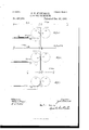
- Fig. 2 is a longitudinal section on line X X of Fig. 3.
- Fig. 3 is a plan view.
- Fig. 4t is an end elevation.
- Figs. 5, 6, and 7 are diagrams illustrating the Way in which a four, six, or eight page paper, respectively, is folded.
- 1 represents the folder-frame.
- the shaft fl. driven by any means and carries a number of tape-pulleys 5 5, around which pass the tapes 6 6.
- These tapes are carried across the machine and pass around pulleysv 7, mounted on shaft S, journaled in bearings 9 10, bolted to the frame.
- the sheets are, carried from a printing-press by these tapes or are fed by hand from the table 11.
- the sides of the frame are raised up in the center, as shown at 12 l2, and on top and between these portions is fastened the slotted plate 13.
- the top of the tapes 6 is iiush or a littlehigher than the top of this plate 13, so that the sheets rest on the same.
- Vorking in the slot in the plate 13 is a first fold mechanism of the character described and claimed in my application, Serial No. 387,972, filed April 7, 18.91, an d which will now be briefly described.
- the same consists of the knife 14, which is journaled by strips l5 on the shaft 1G.
- This shaft 1G is fastened in the crank -arms 17 and 1S.
- the crankarms are journaled in the same line and the crank-arm 17 is journaled in a bearing 10, fastened on the fixed shaft 20, held by brackets 2l 22, bolted to the sides of the frame.
- crank-arm 1S is fastened on a short This shaft isl shaft, which is journaled in ⁇ abearing 23, bolted to the frame, and on the other end of this short shaft is fastened the crank-arm 24 set at one hundred and eighty degrees to the crank-arm 1S.
- the crank-arm 2st has 'a proj ection with a roller which works in a slot cut in the face of the gear 25, running on a stud ⁇ set in a bracket 26, bolted to the side of' the frame.
- This gear 25 is driven as hereinafter described and operates the knife 14.-
- the front edge of the knife is guided in a straight line by means of a roller Working in a slot in ⁇ the bracket 26 and the part 12 and is given a peculiar accelerating and diminishing recip- Irocating movement.
- Figure 1 is a side elevation of the machine.
- the sheet-s are tucked by the knife 14 between the cylinders 27 and 2S, journaled in the frame, as shown in Fig. 2.
- the cylinder 2S has the projecting er or knife 29, which fits in the slot or recess 30 in the cylinder 27.
- the sheet is tucked between cylinders 27 and 2S, so that the same starts in at a point approximately diametrically opposite the slot 30, and the circumference of the cylinders is equal to the width of two sheets plus a small amount for lap, which need not be further considered.
- the sheet is carried down between the cylinders until the knife 29 tucks the same into the recess 30.
- the recess 30 is provided with any of the usual and necessary gripper mechanisms, and the saterrorisms adapted to release the front edge of the sheet as the same comes between the tapes 32 and the cylinder 27.
- This gripper mechanism is so well understood, and as the same,perse,forms no part of my invention, it has not been thought necessary to show the samel on the drawings.
- This point or'fold is then stripped from the cylinder 27 by the stripper-fingers 3l, and the sheet is then carried bythe tapes 32 over the folding-rolls 33 Si. The sheet is then tucked between these rolls by the knife 35, carried by arms 36, fastened on shaft 37, journaled in suitable bearings mounted on the frame.
- This shaft 37 has the crank 38,
- the rolls 33 and 34 are geared so as to run togetherin the usual manner, and the gear 35 of the roll 33 d rives the gear 36, fast on the shaft 37, mounted in suitable bearings.
- the roll 33 is turned down at 38, and keyed on the same is the longitudinally-adjustable trimmer 39, which cooperates with the trimmer 40, fasten ed on the shaft 37.
- the trimmer 39 has a series of cutting-edges, as shown, and the trimmer 40' is held against one of these edges bythe spring 41, bearing against the collar 42.
- Bot-h trimmers are adjustable on their respective shafts, so that the same may be set at any desired point on the sheet to trim off as much as may be necessary.
- This trimmer mechanism is the same as that described and claimed in my patent, No. 301,178, dated July 1, 1884, and a further description thereof is not deemed necessary; but it is to be understood that I am ,not limited to the use of this particular trimmer mechanism, as any other suitable device that will accomplish the same result may be used. From the rolls and 34 and trimmer the sheet is carried over the foldingrolls 43 44 by the usual tapes.(not shown) and tucked between the same by the knife 45, carried by the arms 46 46, fastened on shaft 47,which latteris operated in any of the well-known ways.
- the folded paper then drops into a suitable receiving device 48, each page thereof folded twice or-into quarter size.
- a suitable receiving device 48 each page thereof folded twice or-into quarter size.
- another set of foldingrolls can be added and the three sets placed in the usual position relatively to each other, so that another fold may be given; or, in other words, so that each page may be folded three times or into eighth size.
- the gearing of the rolls 33 34 and the trimmer is covered by a shield 49, so that the sheet will not catch in the same, and a set of guide-fingers 50 are arranged on a shaft and may be swung up to guide the sheet directly onto the tapes 32 for a purpose hereinafter explained.
- the driving mechanism consists of the pulley 50, the shaft of which is journaled inl the frame and which has a pinion 51, meshing into the gear 52 on cylinder 2S, which in turn meshes into gear 53 on cylinder 27, arranged on the inside of the frame.
- Gear 52 meshes into gear 54 on the inside of the frame, and on the same shaft journaled in the frame on the outside thereof is the gear 55 and the bevel-gear 56.
- Gear 55 drives gear 25 through the intermediate 57, journaled on a stud Xed to the frame, thus actuating the cylinders 27 28 and the co-operating knife mechanism thereof.
- the folding-rolls and 34 are driven by means of the bevel-gear 57, fastened on the shaft of the roll 33, bevelgear 53, shaft 59, journaled in suitable bearings fastened to the frame, bevel-gears 60 and 6l, shaft 62, journaled in suitable bearings mounted on the frame, and the bevel-gear 63 on the end of the shaft 62, meshing with the bevel-gear 56.
- the folding-rolls 43 44 are driven from the shaft 62 by means of spurgear 64, meshing with spur-gear 65, fast on a short shaft journaled in a bearing bolted to the frame, and on the other end of this shaft is the bevel-gear 66, which meshes in the bevel-gear 67, fast on the shaft of theroll 44.
- spurgear 64 meshing with spur-gear 65
- spur-gear 65 fast on a short shaft journaled in a bearing bolted to the frame
- bevel-gear 66 which meshes in the bevel-gear 67, fast on the shaft of theroll 44.
- A. suitable paste-box 68 is fastened on the shaft and is adjustable thereon.
- This paste device is of any of the usual constructions, and, if so desired, the paste-roll of the same may be driven from the shaft 8 in the usual manner.
- the sheet is then tucked between the cylin-v ders 27 and 23, and is pulled down between the same until the knife 29 tucks the sheet into the slot 30. (See Fig. 5.)
- the edge of the fold thus made is then carried around and is stripped from the cylinder 27 and is delivered onto the tapes 32 in the form indicated at 69, Fig. 5.
- the edges are trimmed off, as indicated, which thus leaves the ends of the pages free.
- the action of the folder mechanism is so well understood that a description of the next fold or folds is deemed unnecessary.
- the sheet is printed as indicated in Fig. 6, and a pasting-strip is left on one of the sides thereof.
- This six-page sheet is folded and pasted in the same manner as the eight-page sheet, and the only difference is that instead of the third leaf of an eight-page paper a small pasting-strip is formed.
- the four-page paper is tricked into the cylinders 27 2S, so as just to'clear the knife 29, and is guided directly onto the tapes 32 by the guideiingers 50, which are swung up into the position shown in Fig. 7.
- the trimmer mechanism is not necessary with the four-page paper, and the sheet' after being carried by the tapes into the proper position is folded and delivered in the usual manner.
- a folding-machine is provided by which either a four, six, or eight page paper canbe folded, pasted, and trimmed at one operation in a very rapid and accurate manner.
- a device in a paper-folding machine, the combination of the frame, a device, as a set of travcling tapes, to feed the sheets onto the frame, and a paste-box set to deposit a line of paste at a line that is approximately the width of one page from the center of the machine, and two cylinders mounted in the frame on each side of the center of the machine, and a tucker mechanism for starting the sheets between these cylinders, one of said cylinders having a recess and the othera coacting knife or tucker, substantially as described.
Landscapes
- Folding Of Thin Sheet-Like Materials, Special Discharging Devices, And Others (AREA)
Description
' (No'Model.) 5 sheets-sheet 2.
J. H. STQNBMBTZ'.
A PAPER FOLDING MACHINE. No. 465,633.N Patented Dec. 22, 1891. Q
f (N0 MOdGL) 5 Sheets-Sheet 3.
J. H. STONEMBTZ.
PAPER FOLDING MACHINE. No. 465,633. Patented Dec. 22, 1891i.
(Nd Modell.) 5 sheets-sheet 4.
J. H. STONEMETZ. PAPER FOLDING MACHINE.
No. 466,633. Patented Dem-22, 18911.`
x9 Lc N z Q nl #gl Q Vi s Snom/fot (No Model.) 5 sheetssheet 5.
AJ; H. STONBMBTZ. PAPER FOLDING MACHINE.
No.465`,633. Patented Dec. 22, 1891.
' J2 7 Pzm 2 l 3 w l 6". s l. 1 J
WLM/moo@ @wozu/toc "ma Novus wenn: no., nNuYo-Lrmu., wnanmnfau, n. c.
VUNTTl-n STATES PATENT OFFICE.
JOHN Il. STONEMETZ, OF MILLBURY, MASSACHUSETTS, ASSIGNOR TO THE STONEMETZ PRINTERS MACHINERY COMPANY, OF SAME PLACE.
PAPER-FOLDING`NIACHINE.
SPECIFICATION forming part f Letters Patent N0. 465,633, dated December 22, 1891.
Application filed May 12, 1891. Serial No. 392,462. (No model.)
.To wZZ whom it may concern:
Be it known that I, JOHN H. STONEMETZ, a citizen of the United States, residing at Millbury, in the county of Worcester and State of Massachusetts, have invented a new and useful Improvement in Paper-Folding Machines, of which the following is a specification.
The aim of this invention is to produce a compact folding-machine by which a four, six, or eight page paper, as desired, can be folded in the same machine.
To this end the invention consists of the device described and claimed in this specification, and illustrated in the accompanying drawings, in Which- Fig. 2 is a longitudinal section on line X X of Fig. 3. Fig. 3 is a plan view. Fig. 4t is an end elevation. Figs. 5, 6, and 7 are diagrams illustrating the Way in which a four, six, or eight page paper, respectively, is folded.
In detail, 1 represents the folder-frame. Mounted on the top of the frame in suitable bearings 2 and 3 is the shaft fl. driven by any means and carries a number of tape-pulleys 5 5, around which pass the tapes 6 6. These tapes are carried across the machine and pass around pulleysv 7, mounted on shaft S, journaled in bearings 9 10, bolted to the frame. The sheets are, carried from a printing-press by these tapes or are fed by hand from the table 11. The sides of the frame are raised up in the center, as shown at 12 l2, and on top and between these portions is fastened the slotted plate 13. The top of the tapes 6 is iiush or a littlehigher than the top of this plate 13, so that the sheets rest on the same.
Vorking in the slot in the plate 13 is a first fold mechanism of the character described and claimed in my application, Serial No. 387,972, filed April 7, 18.91, an d which will now be briefly described. The same consists of the knife 14, which is journaled by strips l5 on the shaft 1G. This shaft 1G is fastened in the crank -arms 17 and 1S. The crankarms are journaled in the same line and the crank-arm 17 is journaled in a bearing 10, fastened on the fixed shaft 20, held by brackets 2l 22, bolted to the sides of the frame. The other crank-arm 1S is fastened on a short This shaft isl shaft, which is journaled in` abearing 23, bolted to the frame, and on the other end of this short shaft is fastened the crank-arm 24 set at one hundred and eighty degrees to the crank-arm 1S. The crank-arm 2st has 'a proj ection with a roller which works in a slot cut in the face of the gear 25, running on a stud` set in a bracket 26, bolted to the side of' the frame. This gear 25 is driven as hereinafter described and operates the knife 14.- The front edge of the knife is guided in a straight line by means of a roller Working in a slot in `the bracket 26 and the part 12 and is given a peculiar accelerating and diminishing recip- Irocating movement. Figure 1 is a side elevation of the machine.
The details of this mechanism and its operation are set forth at length in my applica- `tion before referred to, and no further description of the same is deemed necessary in this case.
The sheet-s are tucked by the knife 14 between the cylinders 27 and 2S, journaled in the frame, as shown in Fig. 2. The cylinder 2S has the projecting er or knife 29, which fits in the slot or recess 30 in the cylinder 27. The sheet is tucked between cylinders 27 and 2S, so that the same starts in at a point approximately diametrically opposite the slot 30, and the circumference of the cylinders is equal to the width of two sheets plus a small amount for lap, which need not be further considered. The sheet is carried down between the cylinders until the knife 29 tucks the same into the recess 30. The recess 30 is provided with any of the usual and necessary gripper mechanisms, and the sanieis adapted to release the front edge of the sheet as the same comes between the tapes 32 and the cylinder 27. As this gripper mechanism is so well understood, and as the same,perse,forms no part of my invention, it has not been thought necessary to show the samel on the drawings. This point or'fold is then stripped from the cylinder 27 by the stripper-fingers 3l, and the sheet is then carried bythe tapes 32 over the folding-rolls 33 Si. The sheet is then tucked between these rolls by the knife 35, carried by arms 36, fastened on shaft 37, journaled in suitable bearings mounted on the frame. This shaft 37 has the crank 38,
which is connected to any of the usual knife- IOO operating mechanisms,which it is not deemed necessary to show and describe. The rolls 33 and 34 are geared so as to run togetherin the usual manner, and the gear 35 of the roll 33 d rives the gear 36, fast on the shaft 37, mounted in suitable bearings. The roll 33 is turned down at 38, and keyed on the same is the longitudinally-adjustable trimmer 39, which cooperates with the trimmer 40, fasten ed on the shaft 37. The trimmer 39 has a series of cutting-edges, as shown, and the trimmer 40' is held against one of these edges bythe spring 41, bearing against the collar 42. Bot-h trimmers are adjustable on their respective shafts, so that the same may be set at any desired point on the sheet to trim off as much as may be necessary. This trimmer mechanism is the same as that described and claimed in my patent, No. 301,178, dated July 1, 1884, and a further description thereof is not deemed necessary; but it is to be understood that I am ,not limited to the use of this particular trimmer mechanism, as any other suitable device that will accomplish the same result may be used. From the rolls and 34 and trimmer the sheet is carried over the foldingrolls 43 44 by the usual tapes.(not shown) and tucked between the same by the knife 45, carried by the arms 46 46, fastened on shaft 47,which latteris operated in any of the well-known ways. The folded paper then drops into a suitable receiving device 48, each page thereof folded twice or-into quarter size. Of course, if so desired, another set of foldingrolls can be added and the three sets placed in the usual position relatively to each other, so that another fold may be given; or, in other words, so that each page may be folded three times or into eighth size. The gearing of the rolls 33 34 and the trimmer is covered by a shield 49, so that the sheet will not catch in the same, and a set of guide-fingers 50 are arranged on a shaft and may be swung up to guide the sheet directly onto the tapes 32 for a purpose hereinafter explained.
The driving mechanism consists of the pulley 50, the shaft of which is journaled inl the frame and which has a pinion 51, meshing into the gear 52 on cylinder 2S, which in turn meshes into gear 53 on cylinder 27, arranged on the inside of the frame. Gear 52 meshes into gear 54 on the inside of the frame, and on the same shaft journaled in the frame on the outside thereof is the gear 55 and the bevel-gear 56. Gear 55 drives gear 25 through the intermediate 57, journaled on a stud Xed to the frame, thus actuating the cylinders 27 28 and the co-operating knife mechanism thereof. The folding-rolls and 34 are driven by means of the bevel-gear 57, fastened on the shaft of the roll 33, bevelgear 53, shaft 59, journaled in suitable bearings fastened to the frame, bevel-gears 60 and 6l, shaft 62, journaled in suitable bearings mounted on the frame, and the bevel-gear 63 on the end of the shaft 62, meshing with the bevel-gear 56. The folding-rolls 43 44 are driven from the shaft 62 by means of spurgear 64, meshing with spur-gear 65, fast on a short shaft journaled in a bearing bolted to the frame, and on the other end of this shaft is the bevel-gear 66, which meshes in the bevel-gear 67, fast on the shaft of theroll 44. This system of gearing is unimportant, as the various fold mechanisms and cylinders may be driven by any suitable form of gearing that may be designed to suit the special locations of the same.
A. suitable paste-box 68 is fastened on the shaft and is adjustable thereon. This paste device is of any of the usual constructions, and, if so desired, the paste-roll of the same may be driven from the shaft 8 in the usual manner.
The operation will be now described: If an eight-page paper is desired, a sheet four pages Wide, printed in the manner shown in Fig. 5,
is fed sidewise onto the machine, a layer of paste being deposited at the point indicated.
The sheet is then tucked between the cylin-v ders 27 and 23, and is pulled down between the same until the knife 29 tucks the sheet into the slot 30. (See Fig. 5.) The edge of the fold thus made is then carried around and is stripped from the cylinder 27 and is delivered onto the tapes 32 in the form indicated at 69, Fig. 5. Now, as the sheet is carried through the rolls 33 34 to make the next fold, the edges are trimmed off, as indicated, which thus leaves the ends of the pages free. The action of the folder mechanism is so well understood that a description of the next fold or folds is deemed unnecessary. In the case of a six-.page paper the sheet is printed as indicated in Fig. 6, and a pasting-strip is left on one of the sides thereof. This six-page sheet is folded and pasted in the same manner as the eight-page sheet, and the only difference is that instead of the third leaf of an eight-page paper a small pasting-strip is formed. The four-page paper is tricked into the cylinders 27 2S, so as just to'clear the knife 29, and is guided directly onto the tapes 32 by the guideiingers 50, which are swung up into the position shown in Fig. 7. The trimmer mechanism is not necessary with the four-page paper, and the sheet' after being carried by the tapes into the proper position is folded and delivered in the usual manner. Thus it will be seen that a folding-machine is provided by which either a four, six, or eight page paper canbe folded, pasted, and trimmed at one operation in a very rapid and accurate manner.
The details of construction herein shown may be greatly varied by a skilled mechanic without departing from the broad scope of my invention, as expressed in the claims.
Having thus fully described my invention, what I claim, and desire to secure by Letters Patent, is-
l.. In a paper-folding machine, the combination of the frame, the two cylinders journaled in the frame, one of said cylinders carrying a knife or tucker and the other having IOO IZO
a recess in which said knife Works, and a mechanism for tucking the sheets between said cylinders, substantially as described.
2. In a paper-folding machine, the combination of the frame, the two cylinders mounted in the frame, one of the said cylinders carrying` a knife or tucker and the other having a recess in which said knife works, mechanism for tucking` the sheets between said cylinders, and a folder mechanism to which the sheets are delivered from said cylinders, substantially as described.
3. In a paper-folding,` machine, the combination of the frame, the two cylinders mounted in said frame, one of said cylinders carrying a knife or tucker and the other having a recess in which said knife Works, the circumference of said cylinders being approximately equal to the width of two pages of the sheet that is to be folded, and a tucker mechanism set to tuck the sheets between said cylinders at a point approximately diametrically opposite to the said knife and recess, substantially as described.
4. In a paper-folding machine, the combination of the frame, a device, as a set of travcling tapes, to feed the sheets onto the frame, and a paste-box set to deposit a line of paste at a line that is approximately the width of one page from the center of the machine, and two cylinders mounted in the frame on each side of the center of the machine, and a tucker mechanism for starting the sheets between these cylinders, one of said cylinders having a recess and the othera coacting knife or tucker, substantially as described.
5. In a paper'folding machine, the combination of the frame, the tapes 6 6, the pasteboX mounted at the point specified, the cylinders 27 2S geared together, the cylinder 28, having the knife or tucker 29, and the cylinder 27, having the recess 30, and the tucker mechanism for starting` the sheets between said cylinders 27 and 2S, substantially as described.
In testimony whereof I have hereunto set my hand in the presence of two subscribing` witnesses.
JOHN Il, STONEMETZ.
Witnesses:
LoUIs W.VS0UTHGATE, J AMES J. RAFFERTY.
CPD
Publications (1)
| Publication Number | Publication Date |
|---|---|
| US465633A true US465633A (en) | 1891-12-22 |
Family
ID=2534498
Family Applications (1)
| Application Number | Title | Priority Date | Filing Date |
|---|---|---|---|
| US465633D Expired - Lifetime US465633A (en) | stonemetz |
Country Status (1)
| Country | Link |
|---|---|
| US (1) | US465633A (en) |
-
0
- US US465633D patent/US465633A/en not_active Expired - Lifetime
Similar Documents
| Publication | Publication Date | Title |
|---|---|---|
| US556409A (en) | Printing-press | |
| US778637A (en) | Machine for folding paper or other fabrics. | |
| US839899A (en) | Folding-machine. | |
| US195115A (en) | Improvement in duplex printing-machines and folding apparatus combined | |
| US339530A (en) | cbowell | |
| US439306A (en) | Sheet-delivery apparatus for printing-presses | |
| US278777A (en) | Apparatus | |
| US656924A (en) | Paper folder and paster. | |
| US818611A (en) | Folding machinery. | |
| US879510A (en) | Folding mechanism for printing-presses. | |
| US706862A (en) | Web-folding machine. | |
| US465635A (en) | Machine | |
| US512944A (en) | Paper-folder | |
| US713726A (en) | Paper-folding machine. | |
| US452596A (en) | crowell | |
| US729597A (en) | Rotary folding and delivery mechanism. | |
| US197693A (en) | Improvement in sheet-delivering apparatus for printing-machines | |
| US339532A (en) | ceo well | |
| US197700A (en) | Improvement in sheet-delivering apparatus for printing-machines | |
| US472317A (en) | Paper foldina machine- | |
| US212466A (en) | Improvement in paper-folding machines | |
| US742299A (en) | Folding-machine. | |
| US873979A (en) | Rotary printing-press. | |
| US1027657A (en) | Folding mechanism. | |
| US339531A (en) | crowell |