US465357A - Attachment for th rashers - Google Patents
Attachment for th rashers Download PDFInfo
- Publication number
- US465357A US465357A US465357DA US465357A US 465357 A US465357 A US 465357A US 465357D A US465357D A US 465357DA US 465357 A US465357 A US 465357A
- Authority
- US
- United States
- Prior art keywords
- chaff
- grain
- riddle
- elevator
- carrier
- Prior art date
- Legal status (The legal status is an assumption and is not a legal conclusion. Google has not performed a legal analysis and makes no representation as to the accuracy of the status listed.)
- Expired - Lifetime
Links
- 235000013339 cereals Nutrition 0.000 description 34
- 239000000969 carrier Substances 0.000 description 28
- 238000010276 construction Methods 0.000 description 12
- 241000542980 Mimidae Species 0.000 description 6
- 241000681094 Zingel asper Species 0.000 description 4
- 239000002699 waste material Substances 0.000 description 4
- 241000726103 Atta Species 0.000 description 2
- 240000008529 Triticum aestivum Species 0.000 description 2
- 240000008042 Zea mays Species 0.000 description 2
- 238000009825 accumulation Methods 0.000 description 2
- 238000007664 blowing Methods 0.000 description 2
- 150000001875 compounds Chemical class 0.000 description 2
- 230000000694 effects Effects 0.000 description 2
- 239000000463 material Substances 0.000 description 2
- 238000005096 rolling process Methods 0.000 description 2
- 238000000926 separation method Methods 0.000 description 2
- 239000007787 solid Substances 0.000 description 2
- 235000021307 wheat Nutrition 0.000 description 2
Images

Classifications
-
- B—PERFORMING OPERATIONS; TRANSPORTING
- B07—SEPARATING SOLIDS FROM SOLIDS; SORTING
- B07B—SEPARATING SOLIDS FROM SOLIDS BY SIEVING, SCREENING, SIFTING OR BY USING GAS CURRENTS; SEPARATING BY OTHER DRY METHODS APPLICABLE TO BULK MATERIAL, e.g. LOOSE ARTICLES FIT TO BE HANDLED LIKE BULK MATERIAL
- B07B1/00—Sieving, screening, sifting, or sorting solid materials using networks, gratings, grids, or the like
- B07B1/42—Drive mechanisms, regulating or controlling devices, or balancing devices, specially adapted for screens
Definitions
- This invention relates to thrashingmachines, and more especially todevices adapted to beconnected thereto for the purpose of separating the grain from the chaff after it has passed from the thrasher.
- the object of the invention is to effect improvements in devices of this character whereby less waste of grain will occur than in devices of a similar nature heretofore constructed.
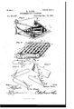
- Figure l is a plan view'of this device complete with the cover removed.
- Fig. 2 is a central longitudinal section thereof.
- Fig. 3 is a perspective view of the riddle and its operating devices.
- Fig. e is a similar View of.. my improved chaff-carrier, partly broken away, the better to show its construction.
- Fig. 5 is an elevation of the front end of thev machine, showing the upper end ofthe return-trough and the switch for directing the grain therefrom to either end ⁇ ofthe cylinder.
- Fig. 6 shows several views of the weightboX for automatically shifting the switch.
- the letter F designates the frame of this device, which is of any preferred size and material, and A is anI air-blast located therein, in the present instance being a rotary fan directing its blast throughthe shakin g-screen or riddle S.
- A is anI air-blast located therein, in the present instance being a rotary fan directing its blast throughthe shakin g-screen or riddle S.
- a return-auger R Across the lower end of this riddle is a return-auger R, above which is a picker P, and the auger delivers through one side of the frame-work into a return trough or elevator E.
- This elevator delivers the grain and chaff into aswitchbox B, whence it is dropped onto the thrashing-cylinder or onto the grain-carrier G, and is returned thereby to the riddle S to be again treated.
- C is my improved chaff-carrier, which is hinged just in rear of the return-auger, and
- the specific construction of these parts is as follows:
- the frame F is of course adaptedy to receive the several parts of this device, and
- vthe fan A is preferably of the shape andrelative size shown, its mouth directing the blast of air through the riddle S.
- This riddle is best seen in Fig. 3 and comprises a curved which carries off the 'chaff that has passed j cranks 7 are connected by vertical links 4 with the upper corners of theframe-work 2 and preferably set opposite to each other.
- This elevator may be a rotating auger within a trough or an endless band having buckets; but its function is to carry the grain and whatever chaff may be therein, which is delivered by the return-auger R, back to the 'grain-carrier orto the thrashing-cylinder to be retreated.
- the object of this is that a more thorough separation may take place and that no grain which may be embedded in the chaff, and hence not pass through the sieve 1, will be lost.
- a switch-box B which is locatedat the front end of this device and over the thrashing-cylinder.
- this box is arranged a switch 2l,pivoted at 22 near its lower end and its free end adapted to move across the mouth 23 of the elevator E.
- Beneath this box is arranged a rectangular guideway 24, preferably composed of rods, and in this guideway travels a weightedwheel 25, whose grooved periphery loosely engages said rods.
- . i f t and 27 is a pair of slotted arms rigidly secured to and depending from the lever 2S, their slots loosely engaging said stub-shafts.
- lever 28 is pivoted near its upper ⁇ end, and a link 29 connects the ends of the switch and lever, as shown.
- the object of this construction is that when the device is located upon a side hill, as is often the case, the weighted wheel will travel to the lower end of the box and will automatically move the switch so as to cause the elevator Eto deliver to the up* per end of the thrashing-cylinder rather than to the lower end, as would be the case if vthe weight and switch were not used.
- the wheat and chaff are then rethrashed, as will be obvious, and fall upon the grain -carrier G, which is a traveling apron, whereby they are delivered onto the riddle again along with the grain which is already thrashed.
- chaff-carrier C which is located in rear of the returnauger R.
- This carrier comprises side plates 30, connected by a screen or sieve 31, and having a solid bottom 32 inclining down ⁇ wardly and delivering into the trough of the return-auger R.
- 33 is a shaft extending through the frarne F and through the lower ends of the side plates and having a sprocket-wheel 34 upon one end, by means of which it is rotated by a suitable chain belt.
- This shaft extends across the lower end of the sieve 3l and a companion shaft 35 extends across the upper end, its ends preferably projecting beyond the side plates 30 and moving in curved slots 36 in the sides of the frame F.
- the carrier is pivotal-ly mounted upon its lower shaft 33 and its up- 'per end can be raised or lowered to set itat a greater or less angle to the riddle, as may be desired.
- On the shafts 33 and 35 are sprocketwheels 37 inside the side plates 30,'and around ⁇ these wheels travel chain belts 3S, which are con nectedacross the carrier by slats 39, thereby forming an apron which moves in the direction of the arrow.
- the grain is fed from the thrashing-machine onto the riddle or shaking-screen S, through which it falls ontov the inclined board I, and is delivered by vthe delivery-auger D to a receptacle in the usual manner; but what grain sticks in the chaff and is blown by the fan off the rid dle S and has heretofore been lost *in this device falls upon the chaff-carrier G and is returned through the auger R and elevator E to be thrashed again. Moreover, what chaff sticks in the fingers 3 of the riddle Sis forced outwardly by the picker l? and dropped into the auger R, when it will be subject to rethrashing.
- the combination with an elevator, a box into which said elevator delivers, and a Vswitch pivoted near its lower end at the center of the box and moving across the mouth ofsaid elevator, of the rectangular guideway below said box, a weighted wheel in said guideway having flanges engaging the sides thereof, stub-shafts on said wheel, a pivotedlever having a pair of slotted arms loosely engaging the stub-shafts, and a link connecting said lever with the lower end of the switch, as and for the purpose set forth.
Landscapes
- Threshing Machine Elements (AREA)
Description
2 sheetssheet 1.
(No Model.)
,ATTA'GHMENT FOR THRASHERS..
Patented Deo. 15, 1891.
fu: ucmms ravens co., wm'ovumn., wnsmsnrsu. n. c.
l(No Model.) 2. Sheets-Sheet 2.
, 5. DAVIS. ATTACHMENT FOR THRASEEBS.
No. 455,357. Patented Dem-15,1891.
Eggs-:21:12:: :zzz-
* IM. f 'l' UNITED STATES PATENT OFFICE.
ROBERT DAVIS, OF MODESTO, CALIFORNIA.
ATTACHMENT Fo'R'THRAsHERs.
SPECIFICATION forming part of Letters Patent No. 465,357, dated December 15, 1891.
Application nea 111.5115, 1891. serai No. 389,051. (No mais.)
To @ZZ whom t may concern:
Be it known that I, ROBERT DAVIS, a citizen of the United States, residing at Modesto, in the county of Stanislaus and State of California, have invented a new and useful Attachment for Thrashers, of which the following is a specification. y
This invention relates to thrashingmachines, and more especially todevices adapted to beconnected thereto for the purpose of separating the grain from the chaff after it has passed from the thrasher.
The object of the invention is to effect improvements in devices of this character whereby less waste of grain will occur than in devices of a similar nature heretofore constructed. f
To this end the invention kconsists of the details of construction hereinafter more fully described and claimed, and as illustrated on the two sheets of drawings, wherein# Figure l is a plan view'of this device complete with the cover removed. Fig. 2 isa central longitudinal section thereof. Fig. 3 is a perspective view of the riddle and its operating devices. Fig. eis a similar View of.. my improved chaff-carrier, partly broken away, the better to show its construction. Fig. 5 is an elevation of the front end of thev machine, showing the upper end ofthe return-trough and the switch for directing the grain therefrom to either end `ofthe cylinder. Fig. 6 shows several views of the weightboX for automatically shifting the switch.
Referring to the said drawings, the letter F designates the frame of this device, which is of any preferred size and material, and A is anI air-blast located therein, in the present instance being a rotary fan directing its blast throughthe shakin g-screen or riddle S. Across the lower end of this riddle is a return-auger R, above which is a picker P, and the auger delivers through one side of the frame-work into a return trough or elevator E. This elevator delivers the grain and chaff into aswitchbox B, whence it is dropped onto the thrashing-cylinder or onto the grain-carrier G, and is returned thereby to the riddle S to be again treated.
C is my improved chaff-carrier, which is hinged just in rear of the return-auger, and
from the riddle.
The specific construction of these parts 'is as follows: The frame F is of course adaptedy to receive the several parts of this device, and vthe fan A is preferably of the shape andrelative size shown, its mouth directing the blast of air through the riddle S. This riddle is best seen in Fig. 3 and comprises a curved which carries off the 'chaff that has passed j cranks 7 are connected by vertical links 4 with the upper corners of theframe-work 2 and preferably set opposite to each other. i By this construction when the sprocket-wheel 8 is driven p by a chain beltf rom some wheel on the machine the lower endof the sievcwill be caused to move longitudinally, while the upper end will be caused to move vertically and also to wabble, and the resultant compound movement of the riddle will Very effectually separate the grain from the chaff. The grain which drops through the riddle falls on an inclined board I and is carried by a delivery-auger D to a suitable receptacle in the ordinary manner. The airblast from the fan blowing through the sieve l drives the chaff over onto the chaff-carrier C, and heretofore some of the grain was often blown over with the chaff and lost. The chaff which travels down the sieve l is caught by the lingers 3 and prevented from falling into the return-auger R, (whose function will be hereinafter described,) and in order to prevent the accumulation of chaff upon these fingers I provide a picker l?, which, as shown, is simply a rotating shaft having fingers, it being understood that these fingers pass between those at the lower end of the riddle.
Thus the chaff is picked from the fingers .3 f
Ico
rotating shaft lllwith a screw-blade 12 thereon, and as the auger turns the blade carries the grain in the trough 10 through an opening in the frame F into the return-trough or elevator E, located outside the frame-work and leading to a point above the grain-carrier G. This elevator may be a rotating auger within a trough or an endless band having buckets; but its function is to carry the grain and whatever chaff may be therein, which is delivered by the return-auger R, back to the 'grain-carrier orto the thrashing-cylinder to be retreated. The object of this is that a more thorough separation may take place and that no grain which may be embedded in the chaff, and hence not pass through the sieve 1, will be lost.
ln Fig. is shown a switch-box B, which is locatedat the front end of this device and over the thrashing-cylinder. X'Vithin this box is arranged a switch 2l,pivoted at 22 near its lower end and its free end adapted to move across the mouth 23 of the elevator E. Beneath this box is arranged a rectangular guideway 24, preferably composed of rods, and in this guideway travels a weightedwheel 25, whose grooved periphery loosely engages said rods. At the center of this wheel isarranged a pair ofoppositely-extendingstub-shafts 26,
. i f t and 27 is a pair of slotted arms rigidly secured to and depending from the lever 2S, their slots loosely engaging said stub-shafts. The
, lever 28 is pivoted near its upper` end, and a link 29 connects the ends of the switch and lever, as shown. The object of this construction is that when the device is located upon a side hill, as is often the case, the weighted wheel will travel to the lower end of the box and will automatically move the switch so as to cause the elevator Eto deliver to the up* per end of the thrashing-cylinder rather than to the lower end, as would be the case if vthe weight and switch were not used.- The wheat and chaff are then rethrashed, as will be obvious, and fall upon the grain -carrier G, which is a traveling apron, whereby they are delivered onto the riddle again along with the grain which is already thrashed.
In Fig. 4: is shown my improved chaff-carrier C, which is located in rear of the returnauger R. This carrier comprises side plates 30, connected by a screen or sieve 31, and having a solid bottom 32 inclining down` wardly and delivering into the trough of the return-auger R. 33 isa shaft extending through the frarne F and through the lower ends of the side plates and having a sprocket-wheel 34 upon one end, by means of which it is rotated by a suitable chain belt. This shaft extends across the lower end of the sieve 3l anda companion shaft 35 extends across the upper end, its ends preferably projecting beyond the side plates 30 and moving in curved slots 36 in the sides of the frame F. By this means the carrier is pivotal-ly mounted upon its lower shaft 33 and its up- 'per end can be raised or lowered to set itat a greater or less angle to the riddle, as may be desired. On the shafts 33 and 35 are sprocketwheels 37 inside the side plates 30,'and around `these wheels travel chain belts 3S, which are con nectedacross the carrier by slats 39, thereby forming an apron which moves in the direction of the arrow. vBy this means what grain and chaff may blow from the riddle over onto the chaff-carrier is dragged by the slats 39 upwardly over the sieve 3l,the chaff being delivered into the waste pile and the grain sifting through the sieve onto the bottom 32 and being dragged thereon by the slats`39 back into the trough 10 of lthe returnauger R. From this point it is carried upwardly by the elevator E, rethrashed, and again fed by the grain-carrier G to theriddle S. It will thus be seen that the grain is fed from the thrashing-machine onto the riddle or shaking-screen S, through which it falls ontov the inclined board I, and is delivered by vthe delivery-auger D to a receptacle in the usual manner; but what grain sticks in the chaff and is blown by the fan off the rid dle S and has heretofore been lost *in this device falls upon the chaff-carrier G and is returned through the auger R and elevator E to be thrashed again. Moreover, what chaff sticks in the fingers 3 of the riddle Sis forced outwardly by the picker l? and dropped into the auger R, when it will be subject to rethrashing. Thus the device is very effectual and prevents any grain ,from being lost. I also consider the specific details of construction above described highly desirable, if not essential, for use in this' connection, although considerable change may be made .therein without departing from the spirit of my of invention.
What is claimed as new isl. In a device of the .character described, the combination, with an elevator, of a box intowhich said elevator delivers, a switch pivoted near its lower end at the center of the box and having its free end moving across the mouth of thev elevator, and a rolling weight located in a guideway and having stub-shafts and a pivoted'lever, one end connected with said switch and the other end having a pair of slotted arms loosely embracing said stubshafts, as and for the purpose set forth.
2. In a device of the character described, the combination, with an elevator, a box into which said elevator delivers, and a Vswitch pivoted near its lower end at the center of the box and moving across the mouth ofsaid elevator, of the rectangular guideway below said box, a weighted wheel in said guideway having flanges engaging the sides thereof, stub-shafts on said wheel, a pivotedlever having a pair of slotted arms loosely engaging the stub-shafts, and a link connecting said lever with the lower end of the switch, as and for the purpose set forth.
3. The herein-described riddle, the same comprising a wire frame-work 2,- a sievemounted upon the same, links risingfrom the IOO IIO
thereof and its free end moving across the mouth of said elevator, a rectangular open guideway, a Weighted Wheel therein havmg anges engaging the sides of the guideway, and connections between said Weight and switch, as and for the purpose hereinbefore' set forth. v In testimony that I claim the foregoing as my own I have hereto affixed my signature 1n presence of two Witnesses.
. ROBERT DAVIS. IIitliesses: t
JN0. B. ZIMDARS, GEO. P. SOHAFEP..
Publications (1)
| Publication Number | Publication Date |
|---|---|
| US465357A true US465357A (en) | 1891-12-15 |
Family
ID=2534222
Family Applications (1)
| Application Number | Title | Priority Date | Filing Date |
|---|---|---|---|
| US465357D Expired - Lifetime US465357A (en) | Attachment for th rashers |
Country Status (1)
| Country | Link |
|---|---|
| US (1) | US465357A (en) |
-
0
- US US465357D patent/US465357A/en not_active Expired - Lifetime
Similar Documents
| Publication | Publication Date | Title |
|---|---|---|
| US465357A (en) | Attachment for th rashers | |
| US555533A (en) | Thrashing-machine | |
| US273391A (en) | rader | |
| US796117A (en) | Grain-separator. | |
| US801141A (en) | Grain-separator. | |
| US826988A (en) | Grain-separator. | |
| US747507A (en) | Pea-harvester. | |
| US620731A (en) | Harvester grain separator and cleaner attachment | |
| US887024A (en) | Threshing-machine. | |
| US261867A (en) | Thrashing and separating machine | |
| US149741A (en) | Improvement in separators for thrashing-machines | |
| US632271A (en) | Threshing-machine. | |
| US1443241A (en) | Thrashing machine | |
| US541936A (en) | Pneumatic straw-stacker | |
| US1179365A (en) | Grain-saving device for threshing-machines. | |
| US735146A (en) | Thresher. | |
| US353591A (en) | Corn sheller and separator | |
| US353885A (en) | Corn-sheller | |
| US820816A (en) | Grain-separator. | |
| US182516A (en) | Improvement in grain thrashing and separating machines | |
| US540576A (en) | butler | |
| US480660A (en) | Quhar | |
| US572086A (en) | Recleaner for threshing-machines | |
| US526200A (en) | Grain-separator | |
| US502619A (en) | Machine for separating peanuts from the vine and for stemming |