US4649729A - Method for manufacturing steel bar with intermittent smooth surface and patterned relief segments, and mine roof bolt product - Google Patents
Method for manufacturing steel bar with intermittent smooth surface and patterned relief segments, and mine roof bolt product Download PDFInfo
- Publication number
- US4649729A US4649729A US06/691,141 US69114185A US4649729A US 4649729 A US4649729 A US 4649729A US 69114185 A US69114185 A US 69114185A US 4649729 A US4649729 A US 4649729A
- Authority
- US
- United States
- Prior art keywords
- bar
- segments
- intermittent
- rollers
- patterned
- Prior art date
- Legal status (The legal status is an assumption and is not a legal conclusion. Google has not performed a legal analysis and makes no representation as to the accuracy of the status listed.)
- Expired - Fee Related
Links
Images


Classifications
-
- B—PERFORMING OPERATIONS; TRANSPORTING
- B21—MECHANICAL METAL-WORKING WITHOUT ESSENTIALLY REMOVING MATERIAL; PUNCHING METAL
- B21B—ROLLING OF METAL
- B21B1/00—Metal-rolling methods or mills for making semi-finished products of solid or profiled cross-section; Sequence of operations in milling trains; Layout of rolling-mill plant, e.g. grouping of stands; Succession of passes or of sectional pass alternations
- B21B1/16—Metal-rolling methods or mills for making semi-finished products of solid or profiled cross-section; Sequence of operations in milling trains; Layout of rolling-mill plant, e.g. grouping of stands; Succession of passes or of sectional pass alternations for rolling wire rods, bars, merchant bars, rounds wire or material of like small cross-section
- B21B1/163—Rolling or cold-forming of concrete reinforcement bars or wire ; Rolls therefor
-
- B—PERFORMING OPERATIONS; TRANSPORTING
- B21—MECHANICAL METAL-WORKING WITHOUT ESSENTIALLY REMOVING MATERIAL; PUNCHING METAL
- B21H—MAKING PARTICULAR METAL OBJECTS BY ROLLING, e.g. SCREWS, WHEELS, RINGS, BARRELS, BALLS
- B21H8/00—Rolling metal of indefinite length in repetitive shapes specially designed for the manufacture of particular objects, e.g. checkered sheets
-
- E—FIXED CONSTRUCTIONS
- E04—BUILDING
- E04C—STRUCTURAL ELEMENTS; BUILDING MATERIALS
- E04C5/00—Reinforcing elements, e.g. for concrete; Auxiliary elements therefor
- E04C5/01—Reinforcing elements of metal, e.g. with non-structural coatings
- E04C5/02—Reinforcing elements of metal, e.g. with non-structural coatings of low bending resistance
- E04C5/03—Reinforcing elements of metal, e.g. with non-structural coatings of low bending resistance with indentations, projections, ribs, or the like, for augmenting the adherence to the concrete
-
- E—FIXED CONSTRUCTIONS
- E04—BUILDING
- E04C—STRUCTURAL ELEMENTS; BUILDING MATERIALS
- E04C5/00—Reinforcing elements, e.g. for concrete; Auxiliary elements therefor
- E04C5/08—Members specially adapted to be used in prestressed constructions
- E04C5/12—Anchoring devices
- E04C5/125—Anchoring devices the tensile members are profiled to ensure the anchorage, e.g. when provided with screw-thread, bulges, corrugations
-
- E—FIXED CONSTRUCTIONS
- E21—EARTH OR ROCK DRILLING; MINING
- E21D—SHAFTS; TUNNELS; GALLERIES; LARGE UNDERGROUND CHAMBERS
- E21D21/00—Anchoring-bolts for roof, floor in galleries or longwall working, or shaft-lining protection
- E21D21/0026—Anchoring-bolts for roof, floor in galleries or longwall working, or shaft-lining protection characterised by constructional features of the bolts
Definitions
- the pattern traditionally found a rebar--usually a diamond-shaped pattern is not ideal for use as a mine roof bolt. Furthermore, it is expensive and time consuming to individually swage or grind off the pattern on each of many hundreds or thousands of bolts after they are cut and before they are threaded.
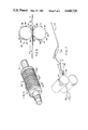
- FIG. 5 is a perspective view of one of two rollers of the type which is used to create the intermittent raised pattern on the surface of the metal bar;
- FIG. 8 A pass design of one type which is suitable for manufacturing bar according to the present invention is shown in FIG. 8.
- the end product of the example set forth here is a bar 43/64 of an inch (1.7 cm.) in diameter.
- the billet described above is first reduced to a billet 133/4(4.4 cm.) inches on a side. Then, during successive passes, the bar assumes the shape and sizes indicated in FIG. 8, concluding with the thickness indicated after the eighth pass.
- the raised segments 13A and 13B shown on the bar after the eighth pass are in exaggerated scale.
Landscapes
- Engineering & Computer Science (AREA)
- Architecture (AREA)
- Structural Engineering (AREA)
- Mining & Mineral Resources (AREA)
- Mechanical Engineering (AREA)
- Civil Engineering (AREA)
- Life Sciences & Earth Sciences (AREA)
- General Life Sciences & Earth Sciences (AREA)
- Geochemistry & Mineralogy (AREA)
- Geology (AREA)
- Metal Rolling (AREA)
Abstract
Description
Claims (4)
Priority Applications (1)
| Application Number | Priority Date | Filing Date | Title |
|---|---|---|---|
| US06/691,141 US4649729A (en) | 1985-01-14 | 1985-01-14 | Method for manufacturing steel bar with intermittent smooth surface and patterned relief segments, and mine roof bolt product |
Applications Claiming Priority (1)
| Application Number | Priority Date | Filing Date | Title |
|---|---|---|---|
| US06/691,141 US4649729A (en) | 1985-01-14 | 1985-01-14 | Method for manufacturing steel bar with intermittent smooth surface and patterned relief segments, and mine roof bolt product |
Publications (1)
| Publication Number | Publication Date |
|---|---|
| US4649729A true US4649729A (en) | 1987-03-17 |
Family
ID=24775320
Family Applications (1)
| Application Number | Title | Priority Date | Filing Date |
|---|---|---|---|
| US06/691,141 Expired - Fee Related US4649729A (en) | 1985-01-14 | 1985-01-14 | Method for manufacturing steel bar with intermittent smooth surface and patterned relief segments, and mine roof bolt product |
Country Status (1)
| Country | Link |
|---|---|
| US (1) | US4649729A (en) |
Cited By (14)
| Publication number | Priority date | Publication date | Assignee | Title |
|---|---|---|---|---|
| EP0351465A1 (en) * | 1986-11-14 | 1990-01-24 | Videx Wire Products (Pty) Limited | Rock bolt |
| US4955219A (en) * | 1986-11-14 | 1990-09-11 | Videx-Wire Products (Proprietary) Limited | Rock bolt |
| US6079907A (en) * | 1995-11-03 | 2000-06-27 | Sistemas S.R.S., S.L. | Reinforcements and a reinforcement system for stabilized earth |
| EP1057968A1 (en) * | 1999-06-01 | 2000-12-06 | Max Dipl.-Ing. Aicher | Method for producing a tip in a steel anchor bolt |
| WO2000079071A1 (en) * | 1999-06-22 | 2000-12-28 | Connector Vinkeveen B.V. | Concrete structure comprising anchor rods and anchor rod |
| US6457909B1 (en) * | 2000-12-22 | 2002-10-01 | Shulin Xu | Multi-purpose anchor bolt assembly |
| US20060144007A1 (en) * | 2005-01-06 | 2006-07-06 | Michael Azarin | Coil bar anchor |
| WO2012131579A1 (en) * | 2011-03-30 | 2012-10-04 | Rand York Castings (Proprietary) Limited | Steel bar |
| US20140010598A1 (en) * | 2010-12-24 | 2014-01-09 | Fci Holdings Delaware, Inc. | Rock Bolt |
| US9010165B2 (en) | 2011-01-18 | 2015-04-21 | Nucor Corporation | Threaded rebar manufacturing process and system |
| US20150113886A1 (en) * | 2013-10-31 | 2015-04-30 | Cheng Chi Steel Co., Ltd. | Pre-embedded Piece, Method for Producing the Same, and Reinforcing Steel Structures Including the Same |
| US9551150B2 (en) | 2010-06-24 | 2017-01-24 | Nucor Corporation | Tensionable threaded rebar bolt |
| USD835977S1 (en) * | 2016-02-08 | 2018-12-18 | Ncm Innovation (Pty) Ltd. | Grout anchored rock bolt |
| CN109877155A (en) * | 2019-03-26 | 2019-06-14 | 巩义市金迪冶金设备有限公司 | A kind of high ductility cold-rolled ribbed bars production technology |
Citations (13)
| Publication number | Priority date | Publication date | Assignee | Title |
|---|---|---|---|---|
| US440095A (en) * | 1890-11-04 | Half to julius arnd | ||
| US1577430A (en) * | 1922-01-20 | 1926-03-16 | Witherow Steel Company | Die-rolled article and method of making the same |
| US1635658A (en) * | 1921-12-15 | 1927-07-12 | Charles S Boardman | Reenforcing bar for concrete |
| US1998970A (en) * | 1931-08-31 | 1935-04-23 | Republic Steel Corp | Die rolled article and die rolling method |
| FR1574005A (en) * | 1968-04-01 | 1969-07-11 | Lamendin Louis | Improvement in anchor rods for mine galleries |
| US3653217A (en) * | 1970-08-03 | 1972-04-04 | Chester I Williams | Rock bolt rod configuration |
| US3693359A (en) * | 1971-01-25 | 1972-09-26 | Said M Karara | Rock stabilizing apparatus |
| US4040232A (en) * | 1974-03-08 | 1977-08-09 | Snow Kenneth T | Building brace |
| US4064729A (en) * | 1977-03-02 | 1977-12-27 | Alex Homery | Metal forming device |
| US4112637A (en) * | 1976-02-16 | 1978-09-12 | Dyckerhoff & Widmann Aktiengesellschaft | Removable press anchor with destructible anchor body |
| US4303354A (en) * | 1979-03-28 | 1981-12-01 | Peabody Coal Company | Mine roof bolting |
| US4338807A (en) * | 1980-08-26 | 1982-07-13 | Armco Inc. | Method of producing improved serrated flats used in the manufacturing of grating |
| US4589803A (en) * | 1984-01-09 | 1986-05-20 | Totten Iii Arthur B | Method and apparatus for installing mine roof supports |
-
1985
- 1985-01-14 US US06/691,141 patent/US4649729A/en not_active Expired - Fee Related
Patent Citations (13)
| Publication number | Priority date | Publication date | Assignee | Title |
|---|---|---|---|---|
| US440095A (en) * | 1890-11-04 | Half to julius arnd | ||
| US1635658A (en) * | 1921-12-15 | 1927-07-12 | Charles S Boardman | Reenforcing bar for concrete |
| US1577430A (en) * | 1922-01-20 | 1926-03-16 | Witherow Steel Company | Die-rolled article and method of making the same |
| US1998970A (en) * | 1931-08-31 | 1935-04-23 | Republic Steel Corp | Die rolled article and die rolling method |
| FR1574005A (en) * | 1968-04-01 | 1969-07-11 | Lamendin Louis | Improvement in anchor rods for mine galleries |
| US3653217A (en) * | 1970-08-03 | 1972-04-04 | Chester I Williams | Rock bolt rod configuration |
| US3693359A (en) * | 1971-01-25 | 1972-09-26 | Said M Karara | Rock stabilizing apparatus |
| US4040232A (en) * | 1974-03-08 | 1977-08-09 | Snow Kenneth T | Building brace |
| US4112637A (en) * | 1976-02-16 | 1978-09-12 | Dyckerhoff & Widmann Aktiengesellschaft | Removable press anchor with destructible anchor body |
| US4064729A (en) * | 1977-03-02 | 1977-12-27 | Alex Homery | Metal forming device |
| US4303354A (en) * | 1979-03-28 | 1981-12-01 | Peabody Coal Company | Mine roof bolting |
| US4338807A (en) * | 1980-08-26 | 1982-07-13 | Armco Inc. | Method of producing improved serrated flats used in the manufacturing of grating |
| US4589803A (en) * | 1984-01-09 | 1986-05-20 | Totten Iii Arthur B | Method and apparatus for installing mine roof supports |
Cited By (18)
| Publication number | Priority date | Publication date | Assignee | Title |
|---|---|---|---|---|
| EP0351465A1 (en) * | 1986-11-14 | 1990-01-24 | Videx Wire Products (Pty) Limited | Rock bolt |
| US4955219A (en) * | 1986-11-14 | 1990-09-11 | Videx-Wire Products (Proprietary) Limited | Rock bolt |
| US6079907A (en) * | 1995-11-03 | 2000-06-27 | Sistemas S.R.S., S.L. | Reinforcements and a reinforcement system for stabilized earth |
| EP1057968A1 (en) * | 1999-06-01 | 2000-12-06 | Max Dipl.-Ing. Aicher | Method for producing a tip in a steel anchor bolt |
| WO2000079071A1 (en) * | 1999-06-22 | 2000-12-28 | Connector Vinkeveen B.V. | Concrete structure comprising anchor rods and anchor rod |
| NL1012410C2 (en) * | 1999-06-22 | 2001-01-10 | R C M Ankertec B V | Concrete construction with anchor rods and anchor rod. |
| US6688071B1 (en) | 1999-06-22 | 2004-02-10 | Connector Vinkeveen B.V. | Concrete structure comprising anchor rods and anchor rod |
| US6457909B1 (en) * | 2000-12-22 | 2002-10-01 | Shulin Xu | Multi-purpose anchor bolt assembly |
| US20060144007A1 (en) * | 2005-01-06 | 2006-07-06 | Michael Azarin | Coil bar anchor |
| US9551150B2 (en) | 2010-06-24 | 2017-01-24 | Nucor Corporation | Tensionable threaded rebar bolt |
| US20140010598A1 (en) * | 2010-12-24 | 2014-01-09 | Fci Holdings Delaware, Inc. | Rock Bolt |
| US9010165B2 (en) | 2011-01-18 | 2015-04-21 | Nucor Corporation | Threaded rebar manufacturing process and system |
| US20150336156A1 (en) * | 2011-01-18 | 2015-11-26 | Nucor Corporation | Threaded rebar manufacturing process and system |
| US9855594B2 (en) * | 2011-01-18 | 2018-01-02 | Nucor Corporation | Threaded rebar manufacturing process and system |
| WO2012131579A1 (en) * | 2011-03-30 | 2012-10-04 | Rand York Castings (Proprietary) Limited | Steel bar |
| US20150113886A1 (en) * | 2013-10-31 | 2015-04-30 | Cheng Chi Steel Co., Ltd. | Pre-embedded Piece, Method for Producing the Same, and Reinforcing Steel Structures Including the Same |
| USD835977S1 (en) * | 2016-02-08 | 2018-12-18 | Ncm Innovation (Pty) Ltd. | Grout anchored rock bolt |
| CN109877155A (en) * | 2019-03-26 | 2019-06-14 | 巩义市金迪冶金设备有限公司 | A kind of high ductility cold-rolled ribbed bars production technology |
Similar Documents
| Publication | Publication Date | Title |
|---|---|---|
| US4649729A (en) | Method for manufacturing steel bar with intermittent smooth surface and patterned relief segments, and mine roof bolt product | |
| KR900000726B1 (en) | Metal strip for use in stabilized earth structures | |
| EP2665567B1 (en) | Threaded rebar manufacturing process and system | |
| DE60114890T2 (en) | METHOD OF MANUFACTURING A COMPONENT WITH THREAD AND COMPONENT MANUFACTURED THEREFOR | |
| EP2000609A1 (en) | Reinforcing bar | |
| EP1512875B1 (en) | Connection device for a wood concrete connection | |
| EP0662018B1 (en) | Hollow bars and method of manufacture | |
| DE60001999T2 (en) | Slitting device for the production of several profiles | |
| US20050108971A1 (en) | Threaded deformed reinforcing bar and method for making the bar | |
| DE1427880A1 (en) | Process for the production of H-beams with protrusions on the outer surface of at least one flange | |
| US5443331A (en) | Threaded bar construction | |
| CA2070485C (en) | Extrusion of aluminium with hollow ribs | |
| DE10337251A1 (en) | Stator and disassembly method and associated device | |
| EP1169524B1 (en) | Wall tie fastener | |
| CA1236343A (en) | Method of rolling a simulated hole in sheet metal without drilling or punching | |
| EP0351465B1 (en) | Rock bolt | |
| JPS5841641A (en) | Manufacture of expanded metal type rolling material | |
| AT216730B (en) | Rolled concrete rebar | |
| EP0174501A2 (en) | Method for bending section bars of metal, in particular of aluminium, with non supported webs, lips or the like | |
| US4506399A (en) | Method of making strut nuts | |
| DE3887326T2 (en) | Anchor bolt. | |
| CA1317489C (en) | Rock bolt | |
| WO2000047349A1 (en) | Method for externally threading a deformed bar | |
| DE2651127A1 (en) | PROCESS FOR REFORMING SPLIT WIRE | |
| DE3200085A1 (en) | Load suspension device for support sections in underground working |
Legal Events
| Date | Code | Title | Description |
|---|---|---|---|
| AS | Assignment |
Owner name: FLORIDA STEEL CORPORATION, HWY. 115 & LAKEVIEW RD. Free format text: ASSIGNMENT OF ASSIGNORS INTEREST.;ASSIGNOR:MC DOWELL, A. DALE;REEL/FRAME:004610/0055 Effective date: 19850108 Owner name: EASTERN COMPANY THE, NAUGATUCK, CT., A CORP OF CT. Free format text: ASSIGNMENT OF ASSIGNORS INTEREST.;ASSIGNOR:VASS, GEORGE S.;REEL/FRAME:004610/0057 Effective date: 19841217 Owner name: FLORIDA STEEL CORPORATION, A CORP OF FL. Free format text: ASSIGNMENT OF ASSIGNORS INTEREST.;ASSIGNOR:EASTERN COMPANY THE, A CORP OF CT.;REEL/FRAME:004610/0059 Effective date: 19841221 Owner name: FLORIDA STEEL CORPORATION, HWY. 115 & LAKEVIEW RD. Free format text: ASSIGNMENT OF ASSIGNORS INTEREST;ASSIGNOR:MC DOWELL, A. DALE;REEL/FRAME:004610/0055 Effective date: 19850108 Owner name: EASTERN COMPANY THE, NAUGATUCK, CT., A CORP OF CT. Free format text: ASSIGNMENT OF ASSIGNORS INTEREST;ASSIGNOR:VASS, GEORGE S.;REEL/FRAME:004610/0057 Effective date: 19841217 Owner name: FLORIDA STEEL CORPORATION, A CORP OF FL., STATELES Free format text: ASSIGNMENT OF ASSIGNORS INTEREST;ASSIGNOR:EASTERN COMPANY THE, A CORP OF CT.;REEL/FRAME:004610/0059 Effective date: 19841221 |
|
| FEPP | Fee payment procedure |
Free format text: PAYOR NUMBER ASSIGNED (ORIGINAL EVENT CODE: ASPN); ENTITY STATUS OF PATENT OWNER: LARGE ENTITY |
|
| FPAY | Fee payment |
Year of fee payment: 4 |
|
| REMI | Maintenance fee reminder mailed | ||
| LAPS | Lapse for failure to pay maintenance fees | ||
| FP | Lapsed due to failure to pay maintenance fee |
Effective date: 19950322 |
|
| AS | Assignment |
Owner name: BANK OF AMERICA, N.A., AS ADMINISTRATIVE AGENT, GE Free format text: SECURITY AGREEMENT;ASSIGNOR:GERDAU AMERISTEEL US INC.;REEL/FRAME:016914/0682 Effective date: 20051028 |
|
| STCH | Information on status: patent discontinuation |
Free format text: PATENT EXPIRED DUE TO NONPAYMENT OF MAINTENANCE FEES UNDER 37 CFR 1.362 |