US4646474A - Drill grinder - Google Patents
Drill grinder Download PDFInfo
- Publication number
- US4646474A US4646474A US06/806,905 US80690585A US4646474A US 4646474 A US4646474 A US 4646474A US 80690585 A US80690585 A US 80690585A US 4646474 A US4646474 A US 4646474A
- Authority
- US
- United States
- Prior art keywords
- seat
- block
- drill bit
- main frame
- gear
- Prior art date
- Legal status (The legal status is an assumption and is not a legal conclusion. Google has not performed a legal analysis and makes no representation as to the accuracy of the status listed.)
- Expired - Fee Related
Links
- 238000000034 method Methods 0.000 description 3
Images


Classifications
-
- B—PERFORMING OPERATIONS; TRANSPORTING
- B24—GRINDING; POLISHING
- B24B—MACHINES, DEVICES, OR PROCESSES FOR GRINDING OR POLISHING; DRESSING OR CONDITIONING OF ABRADING SURFACES; FEEDING OF GRINDING, POLISHING, OR LAPPING AGENTS
- B24B3/00—Sharpening cutting edges, e.g. of tools; Accessories therefor, e.g. for holding the tools
- B24B3/24—Sharpening cutting edges, e.g. of tools; Accessories therefor, e.g. for holding the tools of drills
- B24B3/26—Sharpening cutting edges, e.g. of tools; Accessories therefor, e.g. for holding the tools of drills of the point of twist drills
Definitions
- This invention relates to an improved drill grinder.
- the clearance angle (as defined in FIG. 9-1) and the point angle P (as defined in FIG. 9-2) of a drill bit usually have various specifications in order to meet the requirements of different purposes.
- the desired clearance and point angles of a drill bit have to be obtained by manually controlling the conventional drill grinder therefore it is difficult to achieve the accurate clearance angle or point angl e therefrom.
- FIG. 1 is a perspective view of a preferred embodiment of the present invention
- FIG. 2 is a local perspective view of a preferred embodiment of the present invention
- FIG. 3 is a fragmental perspective view of FIG. 2;
- FIG. 4 is a perspective view of a positioning seat of a preferred embodiment of the present invention.
- FIG. 5-1 shows that the positioning seat cooperates with the clamping means to adjust the position of the drill bit clamped therein;
- FIG. 5-2 is a side view of the clamping means wherein the drill bit is clamped between the first and the second seats;
- FIG. 6 is a simplified top view illustrating the drill bit being contacted with the grinding wheel and defining the vertical distance B thereof;
- FIG. 7 shows that the clearance angle can be accurately defined by the values of A and B
- FIG. 8 shows the grinding position of the drill bit when in operation
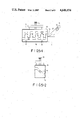
- FIG. 9-1 shows the clearance angle of a drill bit
- FIG. 9-2 shows the point angle of a drill bit.
- an improved drill grinder (10) comprises a main frame (1) which is provided with a grinding means (11) on which a grinding wheel (111) is rotatably disposed.
- the main frame (1) is furnished with a first seat (12) on which a rib (121) is formed.
- a second seat (13) provided with a rib (131) is slidably mounted on the first seat (12) to move along the rib (121) of the first seat (12).
- a third seat (14) is slidably mounted on the second seat (13) to move along the rib (131) of the second seat (13).
- a L-shaped stand (2) is formed with a hole (21).
- a pin (211) passes through the hole (21) of the stand (2) and is secured to the third seat (14) to let the stand (2) pivotally mounted on the third seat (14) thereby capable of changing the relative position between the stand (2) and the grinding wheel (111).
- a shaft (22) passes through the hole (23) of the stand (2) and is provided at one end with a handle (24).
- a block (3) is secured to the other end of the shaft (22).
- the block (3) is provided with a dovetail groove (31).
- the center of the block (3) is formed with a recess (32) in which a gear (33) can be disposed.
- a knob (34) passes through the block (3) to be secured to the gear (33) therefore when the knob (34) is rotated, the gear (33) can be rotated therewith.
- a sliding seat (4) is furnished with a dovetail (41) which corresponds to the dovetail groove (31) of the block (3) and can be moved therealong.
- a rack (42) is secured to the dovetail (41) to mesh in the gear (33) so that when the gear (33) is rotated in a predetermined manner the sliding seat (4) can be moved up or down along the dovetail groove (31) of the block (3).
- the sliding seat (4) is provided with a supporting plate (43) of which the central line (431) intersects the central line (44) of the sliding seat (4) at an angle of 45° (FIG. 6).
- a pair of pins (45) are respectively formed on both sides of the supporting plate (43).
- a clamping means (5) comprises a first seat (51) and a second seat (52).
- the first seat (51) can be adjusted by means of screw (53) to approach the second seat (52) so that the drill bit (54) can be properly clamped between the first and second seats (51) and (52).
- the second seat (52) is provided with a pair of positioning holes (55) (FIG. 5-1) which respectively correspond to the pins (45) of the supporting plate (43).
- the clamping means (5) can be mounted on the supporting plate (43) with the pins (45) thereof respectively inserting into the corresponding positioning holes (55).
- a L-shaped positioning seat (6) is furnished with a slot (61) along which a positioning member (62) can move.
- the positioning member (62) is provided with a screw (63) by which it can be fixed at a specified position.
- the vertical distance from the central axis of the handle (24) to the central axis of the drill bit (54) is defined as B.
- the drill bit (54) is disposed between the first and second seats (51) and (52).
- the positioning member (62) of the positioning seat (6) is fixed at a specified position which is used to set the desired value of B. This will be described later.
- the drill bit (54) is adjusted to contact the positioning member (62) and then is tightly clamped between the first and second seats (51) and (52). After so doing, the desired value of B can be accurately obtained. For example, if the positioning member (62) is fixed at the mark of 40 mm, after completing the above-noted procedure, the corresponding value of B will be set at 40 mm too.
- the clamping means (5) with the drill bit (54) fixed in the desired position is mounted on the supporting plate (43) of the sliding seat (4) as described hereinbefore.
- the vertical distance from the central axis of the handle (24) to the central axis of the drill bit (54) is defined as A (not shown). Since the clearance angle ( ⁇ ) can be accurately defined by the values of A and B we can rotate the knob (34) of the block (3) to adjust the vertical distance A thereof to a predetermined value so as to achieve the desired clearance angle ( ⁇ ). For illustration, referring to FIG. 7, the angle ⁇ 1 can be accurately defined by values B (40 mm) and A (3 mm) while the angle ⁇ 2 by values B (40 mm) and A (9 mm).
- the second and third seats (13) and (14) are properly adjusted to let the portion (C) of the drill bit (54) contact the grinding wheel (111), as shown in the imaginary line of FIG. 8. Then rotate the handle (24) until the portion (D) of the drill bit (54) contacts the grinding wheel (111) as shown in the solid line of FIG. 8.
- the clearance angle ( ⁇ ) of the drill bit (54) can be accurately achieved after repeating the above-noted process a few times.
- rearrange the clamping means (5) to make the pins (45) respectively be inserted into the positioning holes (56) of the first seat (51) and the another clearance angle can be similarly achieved.
- the point angle (P) of the drill bit (54) can be achieved by mans of adjusting the relative position between the stand (2) and the grinding wheel (111).
Landscapes
- Engineering & Computer Science (AREA)
- Mechanical Engineering (AREA)
- Finish Polishing, Edge Sharpening, And Grinding By Specific Grinding Devices (AREA)
Abstract
This invention relates to an improved drill grinder and particularly to one which comprises a main frame. A grinding wheel is disposed on one end of the main frame. A stand is located on the slidable seats which are disposed on the other end of the main frame. The stand is provided with a handle which is used to drive a block in a predetermined manner. A sliding seat having a supporting plate is slidably secured to the block. A clamp having a drill bit clamped therein is disposed on the supporting plate of the sliding seat. In operation, the relative position between the drill bit and the grinding wheel is predetermined by means of adjusting a positioning seat and the sliding seat thereby easily and accurately obtaining the desired clearance angle and point angle of the drill bit.
Description
This invention relates to an improved drill grinder.
The clearance angle (as defined in FIG. 9-1) and the point angle P (as defined in FIG. 9-2) of a drill bit usually have various specifications in order to meet the requirements of different purposes. However, the desired clearance and point angles of a drill bit have to be obtained by manually controlling the conventional drill grinder therefore it is difficult to achieve the accurate clearance angle or point angl e therefrom.
It is, therefore, an object of the present invention to obviate and mitigate the above-noted drawback.
It is the primary object of the present invention to provide an improved drill grinder which can be correctly and quickly operated and is applicable to any sizes of drill bits.
It is another object of the present invention to provide an improved drill grinder which is so simple to operate that even an unskilled person can produce perfect product within a short period.
It is still another object of the present invention to provide an improved drill grinder which is economic to fabricate.
It is a further object of the present invention to provide an improved drill grinder which is practical for use.
FIG. 1 is a perspective view of a preferred embodiment of the present invention;
FIG. 2 is a local perspective view of a preferred embodiment of the present invention;
FIG. 3 is a fragmental perspective view of FIG. 2;
FIG. 4 is a perspective view of a positioning seat of a preferred embodiment of the present invention;
FIG. 5-1 shows that the positioning seat cooperates with the clamping means to adjust the position of the drill bit clamped therein;
FIG. 5-2 is a side view of the clamping means wherein the drill bit is clamped between the first and the second seats;
FIG. 6 is a simplified top view illustrating the drill bit being contacted with the grinding wheel and defining the vertical distance B thereof;
FIG. 7 shows that the clearance angle can be accurately defined by the values of A and B;
FIG. 8 shows the grinding position of the drill bit when in operation;
FIG. 9-1 shows the clearance angle of a drill bit; and
FIG. 9-2 shows the point angle of a drill bit.
Referring to the drawings and particularly to FIGS. 1 to 3, an improved drill grinder (10) comprises a main frame (1) which is provided with a grinding means (11) on which a grinding wheel (111) is rotatably disposed. The main frame (1) is furnished with a first seat (12) on which a rib (121) is formed. A second seat (13) provided with a rib (131) is slidably mounted on the first seat (12) to move along the rib (121) of the first seat (12). A third seat (14) is slidably mounted on the second seat (13) to move along the rib (131) of the second seat (13). A L-shaped stand (2) is formed with a hole (21). A pin (211) passes through the hole (21) of the stand (2) and is secured to the third seat (14) to let the stand (2) pivotally mounted on the third seat (14) thereby capable of changing the relative position between the stand (2) and the grinding wheel (111). A shaft (22) passes through the hole (23) of the stand (2) and is provided at one end with a handle (24). A block (3) is secured to the other end of the shaft (22). The block (3) is provided with a dovetail groove (31). The center of the block (3) is formed with a recess (32) in which a gear (33) can be disposed. A knob (34) passes through the block (3) to be secured to the gear (33) therefore when the knob (34) is rotated, the gear (33) can be rotated therewith.
A sliding seat (4) is furnished with a dovetail (41) which corresponds to the dovetail groove (31) of the block (3) and can be moved therealong. A rack (42) is secured to the dovetail (41) to mesh in the gear (33) so that when the gear (33) is rotated in a predetermined manner the sliding seat (4) can be moved up or down along the dovetail groove (31) of the block (3). The sliding seat (4) is provided with a supporting plate (43) of which the central line (431) intersects the central line (44) of the sliding seat (4) at an angle of 45° (FIG. 6). A pair of pins (45) are respectively formed on both sides of the supporting plate (43).
Referring to FIGS. 5-1 and 5-2, a clamping means (5) comprises a first seat (51) and a second seat (52). The first seat (51) can be adjusted by means of screw (53) to approach the second seat (52) so that the drill bit (54) can be properly clamped between the first and second seats (51) and (52). The second seat (52) is provided with a pair of positioning holes (55) (FIG. 5-1) which respectively correspond to the pins (45) of the supporting plate (43). The clamping means (5) can be mounted on the supporting plate (43) with the pins (45) thereof respectively inserting into the corresponding positioning holes (55). There are another pair of positioning holes (56) (FIG. 1) formed on the first seat (51) and the function thereof is similar to the positioning holes (55) of the second seat (52).
Referring to FIG. 4, a L-shaped positioning seat (6) is furnished with a slot (61) along which a positioning member (62) can move. The positioning member (62) is provided with a screw (63) by which it can be fixed at a specified position. There is a mark (64) formed on the top face of the positioning seat (6) to illustrate the specified position at which the positioning member (62) is located.
Referring to FIG. 6, after the clamping means (5) is mounted on the supporting plate (43) of the sliding seat (4) and the drill bit (54) disposed in the clamping means (5) is arranged to contact the grinding wheel (111) thereof, the vertical distance from the central axis of the handle (24) to the central axis of the drill bit (54) is defined as B.
In operation, firstly the drill bit (54) is disposed between the first and second seats (51) and (52). Secondly, the positioning member (62) of the positioning seat (6) is fixed at a specified position which is used to set the desired value of B. This will be described later. Thirdly, referring to FIGS. 5-1 and 5-2, the drill bit (54) is adjusted to contact the positioning member (62) and then is tightly clamped between the first and second seats (51) and (52). After so doing, the desired value of B can be accurately obtained. For example, if the positioning member (62) is fixed at the mark of 40 mm, after completing the above-noted procedure, the corresponding value of B will be set at 40 mm too. Fourthly, the clamping means (5) with the drill bit (54) fixed in the desired position is mounted on the supporting plate (43) of the sliding seat (4) as described hereinbefore.
The vertical distance from the central axis of the handle (24) to the central axis of the drill bit (54) is defined as A (not shown). Since the clearance angle (θ) can be accurately defined by the values of A and B we can rotate the knob (34) of the block (3) to adjust the vertical distance A thereof to a predetermined value so as to achieve the desired clearance angle (θ). For illustration, referring to FIG. 7, the angle θ1 can be accurately defined by values B (40 mm) and A (3 mm) while the angle θ2 by values B (40 mm) and A (9 mm).
After completing the above-noted procedures, referring to FIG. 8, the second and third seats (13) and (14) are properly adjusted to let the portion (C) of the drill bit (54) contact the grinding wheel (111), as shown in the imaginary line of FIG. 8. Then rotate the handle (24) until the portion (D) of the drill bit (54) contacts the grinding wheel (111) as shown in the solid line of FIG. 8. Thus, the clearance angle (θ) of the drill bit (54) can be accurately achieved after repeating the above-noted process a few times. Then, rearrange the clamping means (5) to make the pins (45) respectively be inserted into the positioning holes (56) of the first seat (51) and the another clearance angle can be similarly achieved.
Also, the point angle (P) of the drill bit (54) can be achieved by mans of adjusting the relative position between the stand (2) and the grinding wheel (111).
Claims (1)
1. An improved drill grinder comprising:
a main frame;
a grinding means being disposed on the main frame, a grinding wheel being rotatably disposed on the main frame;
a first seat on which a rib is formed being mounted on the main frame, a second seat being provided with a rib perpendicular to the rib of the first seat and being slidably mounted on the first seat to move along the rib of the first seat, a third seat being slidably mounted on the second seat to move along the rib of the second seat;
a L-shaped stand being pivotally mounted on the third seat to be capable of changing the relative position thereof to the grinding wheel of the grinding means, the stand being provided with a rotatable handle;
a block being secured to one end of the handle of the stand, the block being provided with a dovetail groove, the block being formed with a recess in which a gear is disposed, a knob passing through the block to be secured to the gear whereby when the knob is rotated, the gear can be rotated therewith;
a sliding seat being furnished with a dovetail which corresponds to the dovetail groove of the block and can be moved therealong, a rack being secured to the dovetail to mesh in the gear of the block whereby when the gear is rotated in a predetermined manner the sliding seat can be moved up or down along the dovetail groove of the block, the sliding seat being furnished with a supporting plate of which the central line intersects the central line of the sliding seat at an angle of 45°;
a clamping means comprising a first seat and a second seat, the first seat capable of being adjusted to approach the second seat so that a drill bit can be properly clamped between the first and second seats, the clamping means capable of being mounted on the supporting plate of the sliding seat whereby the drill bit is arranged to contact the grinding wheel;
a L-shaped positioning seat being furnished with a slot along which a positioning member can move, the positioning member being provided with a screw by which it can be fixed at a specified position, a mark being formed on the positioning seat to illustrate the specified position at which the positioning member is located.
Priority Applications (1)
| Application Number | Priority Date | Filing Date | Title |
|---|---|---|---|
| US06/806,905 US4646474A (en) | 1985-12-09 | 1985-12-09 | Drill grinder |
Applications Claiming Priority (1)
| Application Number | Priority Date | Filing Date | Title |
|---|---|---|---|
| US06/806,905 US4646474A (en) | 1985-12-09 | 1985-12-09 | Drill grinder |
Publications (1)
| Publication Number | Publication Date |
|---|---|
| US4646474A true US4646474A (en) | 1987-03-03 |
Family
ID=25195101
Family Applications (1)
| Application Number | Title | Priority Date | Filing Date |
|---|---|---|---|
| US06/806,905 Expired - Fee Related US4646474A (en) | 1985-12-09 | 1985-12-09 | Drill grinder |
Country Status (1)
| Country | Link |
|---|---|
| US (1) | US4646474A (en) |
Cited By (10)
| Publication number | Priority date | Publication date | Assignee | Title |
|---|---|---|---|---|
| US4769955A (en) * | 1986-08-09 | 1988-09-13 | Reinhold Reiling | Fixture for holding a hole-cutting tool having cutting edges to be ground |
| US4841678A (en) * | 1988-01-19 | 1989-06-27 | Thomas Peter C | Tool sharpening apparatus |
| US5788559A (en) * | 1994-02-25 | 1998-08-04 | Jungnitsch; Paul Lewis | Web adjust drill bit sharpener and method of using |
| US7147546B1 (en) | 2005-10-06 | 2006-12-12 | Professional Tool Manufacturing, Llc | Tool holder with moveable alignment finger |
| US20070058881A1 (en) * | 2005-09-12 | 2007-03-15 | Nishimura Ken A | Image capture using a fiducial reference pattern |
| WO2009157867A1 (en) * | 2008-06-26 | 2009-12-30 | Tj Utveckling Ab | A device for sharpening a twist drill point and a method for its use |
| US7641202B1 (en) | 2005-10-06 | 2010-01-05 | Professional Tool Manufacturing, Llc | End effector with moveable jaw assembly to manipulate an article |
| CN104526473A (en) * | 2014-12-25 | 2015-04-22 | 东莞理工学院 | Tooling device for grinding arc relief angle of tool |
| CN114633155A (en) * | 2022-02-23 | 2022-06-17 | 河南中烟工业有限责任公司 | Grinding explorator and grinding device for twist drill |
| USD1056844S1 (en) | 2021-10-06 | 2025-01-07 | Darex, Llc | Power sharpener |
Citations (4)
| Publication number | Priority date | Publication date | Assignee | Title |
|---|---|---|---|---|
| US3521405A (en) * | 1968-02-14 | 1970-07-21 | Radial Lip Machine Corp | Drill grinding apparatus |
| GB2026357A (en) * | 1978-07-29 | 1980-02-06 | Reiling R | Fixture for holding a twist drill to be reground |
| DE3039649A1 (en) * | 1979-04-18 | 1982-05-19 | Karl 7539 Kämpfelbach Reiling | Twist drill grinding unit - has swivelable drill clamp on slidable and swivelable support and slidable and swivelable grind disc unit |
| US4471581A (en) * | 1982-09-09 | 1984-09-18 | Darex Corporation | Universal twist drill sharpener apparatus |
-
1985
- 1985-12-09 US US06/806,905 patent/US4646474A/en not_active Expired - Fee Related
Patent Citations (4)
| Publication number | Priority date | Publication date | Assignee | Title |
|---|---|---|---|---|
| US3521405A (en) * | 1968-02-14 | 1970-07-21 | Radial Lip Machine Corp | Drill grinding apparatus |
| GB2026357A (en) * | 1978-07-29 | 1980-02-06 | Reiling R | Fixture for holding a twist drill to be reground |
| DE3039649A1 (en) * | 1979-04-18 | 1982-05-19 | Karl 7539 Kämpfelbach Reiling | Twist drill grinding unit - has swivelable drill clamp on slidable and swivelable support and slidable and swivelable grind disc unit |
| US4471581A (en) * | 1982-09-09 | 1984-09-18 | Darex Corporation | Universal twist drill sharpener apparatus |
Cited By (15)
| Publication number | Priority date | Publication date | Assignee | Title |
|---|---|---|---|---|
| US4769955A (en) * | 1986-08-09 | 1988-09-13 | Reinhold Reiling | Fixture for holding a hole-cutting tool having cutting edges to be ground |
| US4841678A (en) * | 1988-01-19 | 1989-06-27 | Thomas Peter C | Tool sharpening apparatus |
| US5788559A (en) * | 1994-02-25 | 1998-08-04 | Jungnitsch; Paul Lewis | Web adjust drill bit sharpener and method of using |
| US20070058881A1 (en) * | 2005-09-12 | 2007-03-15 | Nishimura Ken A | Image capture using a fiducial reference pattern |
| US7641202B1 (en) | 2005-10-06 | 2010-01-05 | Professional Tool Manufacturing, Llc | End effector with moveable jaw assembly to manipulate an article |
| US7147546B1 (en) | 2005-10-06 | 2006-12-12 | Professional Tool Manufacturing, Llc | Tool holder with moveable alignment finger |
| WO2009157867A1 (en) * | 2008-06-26 | 2009-12-30 | Tj Utveckling Ab | A device for sharpening a twist drill point and a method for its use |
| CN102099154A (en) * | 2008-06-26 | 2011-06-15 | Tj开发公司 | A device for sharpening a twist drill point and a method for its use |
| US20110171884A1 (en) * | 2008-06-26 | 2011-07-14 | Tj Utveckling Ab | Device for sharpening a twist drill point and a method for its use |
| JP2011525862A (en) * | 2008-06-26 | 2011-09-29 | ティジェイ ユトベクリング アーベー | Apparatus for polishing twist drill tip and method of use thereof |
| US8425277B2 (en) | 2008-06-26 | 2013-04-23 | Tj Utveckling Ab | Device for sharpening a twist drill point and a method for its use |
| CN102099154B (en) * | 2008-06-26 | 2015-04-29 | Tj开发公司 | A device for sharpening a twist drill point and a method for its use |
| CN104526473A (en) * | 2014-12-25 | 2015-04-22 | 东莞理工学院 | Tooling device for grinding arc relief angle of tool |
| USD1056844S1 (en) | 2021-10-06 | 2025-01-07 | Darex, Llc | Power sharpener |
| CN114633155A (en) * | 2022-02-23 | 2022-06-17 | 河南中烟工业有限责任公司 | Grinding explorator and grinding device for twist drill |
Similar Documents
| Publication | Publication Date | Title |
|---|---|---|
| US5711356A (en) | Finger joint template | |
| US4646474A (en) | Drill grinder | |
| JP4541384B2 (en) | Key cutting method | |
| US4787432A (en) | Apparatus and method for producing mortise and tenon joints | |
| KR101504460B1 (en) | Jig base for double angle processing | |
| US5979283A (en) | Miter guide | |
| US3748940A (en) | Portable punch | |
| JPS5948362B2 (en) | support positioning device | |
| US2726690A (en) | Contour guide for routers | |
| KR20030015027A (en) | Jig for milling machine | |
| US2704951A (en) | Vise mounting providing tiltable and rotatable adjustment | |
| US4913206A (en) | Router guide assembly | |
| US2769466A (en) | Lathe attachment | |
| US2764380A (en) | Support | |
| EP1049564B1 (en) | Coping apparatus | |
| US5163664A (en) | Alignment tool for machine vise and the like | |
| US2521231A (en) | Vise and jig | |
| US4566227A (en) | Auxiliary device for re-grinding of spiral drills | |
| CN214560686U (en) | Positioning clamping device and direction-changing positioning locking device | |
| US3974571A (en) | Sine bar | |
| US6145367A (en) | Workpiece holder for press brake | |
| US5816898A (en) | Cutter sharpening device | |
| US6016854A (en) | Woodworking apparatus for making curved components | |
| JP2975521B2 (en) | Polishing angle setting device for polishing machine | |
| US4304276A (en) | Router table for cutting laminated plastics |
Legal Events
| Date | Code | Title | Description |
|---|---|---|---|
| FEPP | Fee payment procedure |
Free format text: PAYOR NUMBER ASSIGNED (ORIGINAL EVENT CODE: ASPN); ENTITY STATUS OF PATENT OWNER: SMALL ENTITY |
|
| FPAY | Fee payment |
Year of fee payment: 4 |
|
| REMI | Maintenance fee reminder mailed | ||
| LAPS | Lapse for failure to pay maintenance fees | ||
| FP | Lapsed due to failure to pay maintenance fee |
Effective date: 19950308 |
|
| STCH | Information on status: patent discontinuation |
Free format text: PATENT EXPIRED DUE TO NONPAYMENT OF MAINTENANCE FEES UNDER 37 CFR 1.362 |