US4644608A - Thigh deboner - Google Patents
Thigh deboner Download PDFInfo
- Publication number
- US4644608A US4644608A US06/570,914 US57091484A US4644608A US 4644608 A US4644608 A US 4644608A US 57091484 A US57091484 A US 57091484A US 4644608 A US4644608 A US 4644608A
- Authority
- US
- United States
- Prior art keywords
- bone
- conveyor
- meat
- slot
- along
- Prior art date
- Legal status (The legal status is an assumption and is not a legal conclusion. Google has not performed a legal analysis and makes no representation as to the accuracy of the status listed.)
- Expired - Fee Related
Links
- 210000000689 upper leg Anatomy 0.000 title claims abstract description 26
- 210000000988 bone and bone Anatomy 0.000 claims abstract description 131
- 235000013372 meat Nutrition 0.000 claims abstract description 129
- 244000144977 poultry Species 0.000 claims abstract description 50
- 210000001694 thigh bone Anatomy 0.000 claims description 25
- 241000282472 Canis lupus familiaris Species 0.000 claims description 11
- 230000000717 retained effect Effects 0.000 claims description 11
- 238000000034 method Methods 0.000 abstract description 4
- 210000002414 leg Anatomy 0.000 description 7
- 206010040844 Skin exfoliation Diseases 0.000 description 5
- 230000000750 progressive effect Effects 0.000 description 4
- 210000002435 tendon Anatomy 0.000 description 4
- 241000287828 Gallus gallus Species 0.000 description 3
- 238000013459 approach Methods 0.000 description 3
- 230000000694 effects Effects 0.000 description 3
- JOYRKODLDBILNP-UHFFFAOYSA-N Ethyl urethane Chemical compound CCOC(N)=O JOYRKODLDBILNP-UHFFFAOYSA-N 0.000 description 2
- 230000000712 assembly Effects 0.000 description 2
- 238000000429 assembly Methods 0.000 description 2
- 239000012530 fluid Substances 0.000 description 2
- 229910001220 stainless steel Inorganic materials 0.000 description 2
- 239000010935 stainless steel Substances 0.000 description 2
- XLYOFNOQVPJJNP-UHFFFAOYSA-N water Substances O XLYOFNOQVPJJNP-UHFFFAOYSA-N 0.000 description 2
- 241000286209 Phasianidae Species 0.000 description 1
- 238000010521 absorption reaction Methods 0.000 description 1
- 239000003638 chemical reducing agent Substances 0.000 description 1
- 238000004140 cleaning Methods 0.000 description 1
- 239000000463 material Substances 0.000 description 1
- 238000012986 modification Methods 0.000 description 1
- 230000004048 modification Effects 0.000 description 1
- 238000004806 packaging method and process Methods 0.000 description 1
Images


Classifications
-
- A—HUMAN NECESSITIES
- A22—BUTCHERING; MEAT TREATMENT; PROCESSING POULTRY OR FISH
- A22C—PROCESSING MEAT, POULTRY, OR FISH
- A22C21/00—Processing poultry
- A22C21/0069—Deboning poultry or parts of poultry
- A22C21/0076—Deboning poultry legs and drumsticks
-
- A—HUMAN NECESSITIES
- A22—BUTCHERING; MEAT TREATMENT; PROCESSING POULTRY OR FISH
- A22C—PROCESSING MEAT, POULTRY, OR FISH
- A22C17/00—Other devices for processing meat or bones
- A22C17/04—Bone cleaning devices
Definitions
- the present invention relates to an apparatus and a method for deboning poultry pieces and more particularly to a unique apparatus for removing the meat from an elongated bone of a poultry thigh piece, leg and the like.
- Various methods and machines have been used to separate an eviscerated poultry carcass into its various component pieces or parts for subsequent processing, packaging and sale.
- the cut-up operations typically involve removal of the meat components from the carcass. Cut-up and deboning operations have been and continue to be performed by hand.
- the eviscerated carcasses may be mounted on shackles along a processing line.
- the component parts are removed by manual cutting. The parts may be subsequently processed to remove the meat from the bones.
- a machine which has been developed for deboning poultry legs, thighs and the like may be found in U.S. Pat. No. 4,327,463 entitled SINGLE STATION ANATOMICAL SECTION DE-BONING MACHINE and issued on May 4, 1982 to Eugene G. Martin.
- the machine of this patent includes a gripper blade assembly which engages and retains an end of the bone.
- a head deboning assembly includes a set of blades through which the bone is pulled by the gripper blade assembly. The deboning assembly in effect pulls the bone out of the meat portion or peels the meat back along the longitudinal axis of the elongated bone.
- Prior approaches have not been readily adaptable to different types of poultry such as chicken or turkeys. Also, the prior machines have been relatively complex and/or have not achieved the desired maximum removal of the meat from the bones. The water jet approaches also present problems with excessive water absorption by the meat which can make the meat components unacceptable.
- a unique apparatus and method are provided for peeling and folding the meat down the lateral sides of an elongated bone and then cutting or severing the meat from the bone on a continuous, progressive basis.
- the apparatus includes means for conveying the poultry part longitudinally. Provision is made to engage the poultry part and progressively fold or peel the meat until it is retained along a longitudinal edge of the bone.
- a cutting means severs the meat from the bone.
- the poultry part is initially fed into a hold-down assembly.
- a longitudinal edge of the part is scored and initial progressive folding or peeling down of the meat is accomplished.
- the part then passes into a finish peel-down assembly which removes the meat along the lateral sides of the bone.
- the part then engages a ramp assembly which defines a slot.
- the bone passes over the ramp and the peeled down meat passes through the slot.
- the meat is then severed by a rotary cutting blade which overlies the slot between the bone and the top surface of the ramp.
- the progressive peeling or folding of the meat down along the lateral sides of the longitudinally moving bone removes substantially all of the meat from the irregularly shaped bones of the poultry pieces.
- the cutting assembly including the ramp and rotary blade, cleanly severs the meat from the bone. The meat falls into a catch pan and the bone is conveyed out of the discharge end of the apparatus.
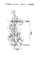
- FIG. 1 is a side, elevational view showing the basic layout of a deboning apparatus in accordance with the present invention
- FIG. 2 is a perspective, end view of the feed end of the apparatus
- FIG. 3 is a fragmentary, perspective view showing the left side of the apparatus
- FIG. 4 is a fragmentary, right side perspective view of the apparatus
- FIG. 5 is a fragmentary, perspective view showing the scoring knives of the apparatus
- FIG. 6 is a fragmentary, perspective view showing a portion of the peel-down subassembly incorporated in the present invention.
- FIG. 7 is a fragmentary, perspective view showing a portion of the peel-down subassembly and the cutter subassembly;
- FIG. 8 is a fragmentary, perspective view showing the cutter subassembly
- FIG. 9 is a fragmentary, perspective view showing the cutter subassembly
- FIG. 10 is a fragmentary, perspective view showing the discharge end of the apparatus
- FIG. 11 is a fragmentary, partially sectioned view of a cup knife
- FIG. 12 is a plan view of the cup knife of FIG. 11;
- FIG. 13 is a bottom, plan view of a hold-down bar subassembly incorporated in the present invention.
- FIG. 14 is a fragmentary, side-elevational view of the hold-down subassembly
- FIG. 15 is a fragmentary, top plan view of the peel-down or squeegee subassembly
- FIG. 16 is a top, plan view of a ramp plate
- FIG. 17 is a right-side, elevational view of the ramp plate of FIG. 16;
- FIG. 18 is a top, plan view of another ramp plate
- FIG. 19 is a side elevational view of the ramp plate of FIG. 18.
- FIG. 20 is a fragmentary, side elevational view schematically illustrating a portion of the peel-down subassembly and the cutter subassembly.
- FIG. 1 A preferred embodiment of the deboner apparatus in accordance with the present invention is illustrated generally in FIG. 1 and designated by numeral 10.
- Apparatus 10 includes an elongated frame 12 which supports a conveyor 14 having feed end 16 and discharge end 18. Also supported on the frame is a peel-down or fold-down subassembly generally designated 20 and a cutting subassembly generally designated 22. Supported at feed end 16 of apparatus 10 is a feed tray 24.
- Conveyor 14 is of the endless, flexible, chain type.
- Conveyor 14 includes a sprocket 26 rotatably mounted adjacent the feed end 16 and a driven sprocket 28 enclosed within chain guard 30.
- Sprocket 28 is driven by a suitable motor 32 through a speed reducer 34.
- Extending around sprockets 26, 28 is an endless roller chain schematically shown in FIG. 1 and designated 36.
- Chain 36 along the side plates thereof includes a plurality of generally V-shaped dogs 38.
- the conveyor therefore, includes two spaced, parallel rows of dogs 38.
- the dogs engage the poultry piece to transport the piece through the peel-down subassembly 20 and the cutting subassembly 22 along an upper run of chain 36.
- Arrow A in FIGS. 3, 4, 5, 6, 7 and 9 indicates the direction of travel of chain 36.
- Chain guide 42 Supported on frame 12 and extending the length of the frame below the upper run of the conveyor is a chain guide 42.
- Chain guide 42 is preferably formed from a USDA approved ultra high molecular weight plastic.
- Supported on frame 12 below chain guide 42 is a catch pan 44.
- a discharge chute 46 is supported on frame 12 at discharge end 18.
- Suitable controls are mounted on frame 12 within a liquid-tight control box 50.
- a safety limit switch 52 having a limit switch lever 54 which engages a panic stop bar 56.
- peel-down assembly 20 includes hold-down subassembly 60 and a final or finish peel-down or squeegee subassembly 62.
- Cutting subassembly 22 includes a ramp or plate structure 64 and a rotary cutting blade 66 driven by a suitable motor 68.
- feed tray 24 supports a tendon or cup knife subassembly 72.
- Subassembly 72 includes a support plate and guard structure 74 through which a drive shaft 76 of a drive motor 78 extends.
- Shaft 76 supports and rotates a rotary cup knife 80 illustrated in FIGS. 11 and 12.
- Cup knife 80 includes a cylindrical portion 82 joined to base 84.
- Base 84 defines a bore 86.
- Knife 80 is secured to shaft 76 by a suitable set screw.
- Knife 80 includes an inwardly angled flange or truncated cone portion 88. Portion 88 defines a cup blade 90.
- the apparatus when the apparatus is used to debone a poultry thigh piece, such as a turkey thigh, the large end of the thigh bone is inserted into the cup knife 80 to loosen meat from the large end thereof and sever the tendons at such end of the bone. This increases the meat yield. Edge 90 of the knife cuts into the tendons and meat along the end of the bone.
- Hold-down subassembly 60 is best seen in FIGS. 2, 3, 13 and 14.
- Subassembly 60 includes parallel, elongated support or mounting plates 100. Secured to plates 100 are a plurality of paired, tandemly arranged hold-down bars or guide rods 102, 104, each pair including a bar 102 and a bar 104.
- each bar 102, 104 includes an elongated, generally straight portion 106 joined to an intermediate, downwardly and outwardly angled portion 108 which in turn is joined to a trailing or free portion 110.
- Bars 102, 104 are supported on frame 12 from plates 100 so as to extend longitudinally along and immediately adjacent the sides of conveyor chain 36. This is best seen in FIGS. 2 and 3.
- Subassembly 60 is vertically adjustable on frame 12 by threaded members 112 received in frame cross pieces 114. The vertical spacing, therefore, of rods 102, 104 above conveyor chain 36 may then be adjusted to accommodate different size poultry parts.
- a poultry part such as a turkey thigh piece 120 is fed into the machine with a small end 122 of bone 124 entering the apparatus first.
- the so-called white knuckle 126 of the small end is positioned so as to extend upwardly into the slot defined by the spaced bars 102, 104.
- a lower longitudinal surface of the bone is engaged by the drive dogs 38.
- Subassembly 60 holds the piece in engagement with the conveyor so that it moves through the machine.
- each scraper or scoring blade assembly is supported on frame 12.
- a pair of tandemly arranged scraper blade or scoring knife assemblies 130 be supported on frame 12.
- Each scoring knife subassembly includes a knife holder 132 supporting a knife 134. Knife holder 132 is rotatably supported on a pivot pin or axle 136.
- a lever 138 is joined to holder 132. An upper end of lever 138 is engaged by a coil spring 140 at an end 141 of the spring.
- Blade 132 extends towards the conveyor chain 36 between the support plates 100 of subassembly 60. Blades 132 overlie the longitudinal axis of poultry part 120. As the poultry piece passes through subassembly 60, knives 132 engage and scrape or score an upper longitudinal edge of the piece. This aids in the initial peel down action accomplished by the hold-down rods 102, 104. Knives 132 insure more complete removal or folding down of the meat from the bone.
- squeegee subassembly 62 includes a subframe 160 having a pair of spaced mounting plates 162, 164. Bolted or otherwise suitably secured to mounting plates 162, 164 is a pair of squeegee plates 166. Plates 166, as seen in FIGS. 6 and 15, are positioned with opposed lateral edges 168 in spaced parallel relationship to define a peel-down slot 170. Ends 172 of plates 166 are notched as 174 to define an enlarged portion 176 for slot 170.
- Each assembly 180 includes a scraper knife 182 adjustably and pivotally mounted on plate 162 or 164 by fastener 184 and a support 196.
- a coil spring 186 has an end 188 fixed to frame 12 at a pin 190. Opposite end 192 of coil spring 186 is fixed to a lever 194. Lever 194 engages the knife support 196 (FIG. 7). Spring 186 biases the scoring knife 182 into the enlarged portion 176 of slot 170. Knives 182 will engage poultry part 120 along the lateral sides thereof, as schematically shown in FIG. 15, as the part passes through slot portion 176.
- the squeegee plates 166 are supported above the conveyor at an incline with respect to the upper run of the conveyor. Plates 166 are angled downwardly with the lateral edges of the plates at slot portion 176 overlying the sides of the chain and the drive dogs. As schematically shown in FIG. 20, poultry part 120 will pass through slot 170 and enlarged slot portion 176. As the part passes through the slot, the lateral edges of the plates will move along the lateral sides of the part in a wiping or peeling fashion to complete the peel-down operation.
- the scoring knives 182 assist in separating the meat from the bone by scoring along the lateral sides of the bone as it passes through the squeegee.
- the plates are formed from a plastic material, such as urethane.
- the plates peel or fold down the meat along the lateral sides of the bone by wiping the bone in a manner similar to that of a squeegee.
- the specific angle of the plates with respect to the conveyor chain is not believed to be critical. It is merely important that the plates be angled sufficiently so that the poultry piece will come in contact with the lateral edges of the plates along the entire lateral sides of the poultry part.
- the meat After the poultry part passes through the squeegee subassembly 62, the meat has been folded down along the lateral edges until it is retained on the bone principally along the lower longitudinal edge of the bone. The meat will be secured to the bone and overlie both sides of the upper run of the conveyor.
- the bone after leaving the squeegee subassembly, then enters the cutting subassembly 22 of the apparatus.
- Subassembly 22 is best seen in FIGS. 7, 8, 9 and 10.
- the subassembly is also schematically illustrated in FIG. 20.
- subassembly 22 includes a rotary cutter or blade 66 fixed to drive shaft 210 of drive motor 68.
- a blade guard 212 is positioned around blade 66.
- Cutter blade 66 is mounted for movement towards and away from conveyor chain 36 in a direction generally perpendicular to the longitudinal direction of movement of chain 36 which is moving in a direction indicated by arrow A (FIG. 9).
- the entire subassembly 22 is supported on a subframe 214 which is secured to pivoting links 216.
- Frame structure 214 and links 216 permit the entire cutter subassembly to be pivoted up and away from chain 36 for cleaning purposes, as illustrated in FIGS. 8 and 9.
- Subassembly 22 further includes a ramp structure 220.
- Ramp 220 has a pair of plates 222, 224 mounted in opposed, spaced, parallel relationship to define a guide slot 226.
- Guide slot 226 defined by the plates overlies the longitudinal centerline of conveyor chain 36 when in the position shown in FIG. 7.
- plate 222 includes a recess 227 to receive shaft 210 when cutter blade 66 is moved into position.
- Each of the plates 222, 224 includes a beveled leading edge 228 which extends along lateral edge 230 and into the leading or opening portion of slot 226.
- the poultry piece When the cutting assembly is in position overlying chain 36, the poultry piece is moved into engagement with the ramp so that the bone is forced over the top surface of the ramp.
- the folded down or peeled down meat is forced through the guide slot 226.
- the rotary guide blade 66 overlies slot 226 and is positioned beneath bone 124 of the piece.
- the rotary cutter severs the meat from the bone as it passes across plates 222, 224.
- Conveyor dogs 38 in engagement with the meat force the bone through the cutting subassembly.
- the meat falls into the catch pan 44.
- the bone is conveyed by the conveyor chain 36 to the discharge chute 46.
- the operation of the deboner in accordance with the present invention should be readily apparent to one of ordinary skill in the poultry processing art.
- the deboner while principally developed to remove meat from an elongated turkey thigh bone, would be usable to remove meat from other elongated poultry parts, including drumsticks, chicken parts and the like.
- the conveyor chain drive and the cutter motor are activated through conventional controls positioned within the control box 50.
- the thigh piece is initially prepared by loosening the meat from a large knuckel or end.
- the operator inserts the large end into cup knife 80 which is driven by cup knife motor 78.
- the initial preparation involves loosening of the meat and cutting of the tendons at the large end of the bone. Due to a natural curvature of the bone from the small end to the large end, this step insures better yields.
- the bone passes through the squeegee, since it is curved, both lateral sides are not wiped as efficiently. Loosening of the meat at the big end counteracts this problem and increases yield or meat removal.
- the piece is inserted between guide bars 102, 104 of the first pair of bars.
- the bars center the piece on the conveyor.
- Dogs 38 on the conveyor chain engage the poultry piece and transport it through the hold-down subassembly 60.
- angled portions 108 of the guide bars contact the meat and in a progressive fashion begin folding the meat down and along the lateral sides of the longitudinally extending bone.
- the thigh piece is contacted by scoring knives 132. This cutting along an upper longitudinal edge increases the efficiency of the folding down of the meat as it passes through the hold-down subassembly.
- the final or finish peeling is accomplished as the piece passes through the squeegee or final peel-down subassembly 62.
- the enlargement 176 in the peel-down slot 170 provides room for the knuckle, as well as the trailing end of the bone to pass.
- the spring biased knives 182 at enlarged portion 176 of slot 170 ride along the lateral edges or sides of the bone. This increases the efficiency of the squeegee operation. Due to the angular relationship of the squeegee with respect to the plane of travel of the conveyor, the lateral edges of the squeegee plates engage the meat and, in effect, wipe down along the lateral sides of the bone. This accomplishes a finish or final fold down of the meat until it is retained on the bone principally along the lower longitudinal edge of the bone.
- hold-down rods 102, 104 are formed from stainless steel and have a diameter of approximately 0.6 inches. Portion 106 of the leading pair of rods has a length of approximately 11 inches. Portions 108 of each rod 102, 104 have a length of approximately 4 inches, and trailing ends 110 have a length of approximately 1 inch. Portions 106 of the second and third pairs of rods 102, 104 have a length of approximately 6.5 inches. The distance between the centers of the first and second pairs of hold-down rods 102, 104 at the trailing ends 110 is approximately 3.75 inches.
- each guide rod 102, 104 are angled at an angle designated B in FIG. 14 of approximately 25 degrees.
- the squeegee plates 166 are fabricated from 3/8 inch thick 80 Durometer urethane which is USDA approved. Presently existing squeegees have an overall length of approximately 7 inches and an overall width of approximately 2 inches. The spacing or transverse dimension of slot 170 may be adjusted to accommodate the size of product being passed through the deboner. The plates are positioned so that the bone ends will pass through the enlarged portion 176.
- the ramp plates 222, 224 are fabricated from 1/4 ⁇ 2 inch stainless steel.
- the plates have an overall length of approximately 12 inches.
- the taper or ramp portion at the leading edge of the plates extends into the slot approximately 3.25 inches. Satisfactory operation has been obtained with the plates positioned so that the slot 226 defined therebetween is approximately 3/32 of an inch.
- the rotary cutting blade 66 has an approximately 4 inch diameter blade.
- the deboner in accordance with the present invention efficiently removes the meat from an elongated poultry piece.
- the portion of the bone which is fed into the machine in effect, guides or stabilizes the part as it moves through the machine.
- the white knuckle and the trailing end of the bone are contacted and retained by the hold-down bar assembly.
- the squeegee plates effectively engage and wipe the lateral edges of the bone so that the meat is positioned in a tucked-in manner along the lower longitudinal edge.
- the apparatus efficiently handles different sized poultry pieces.
- the apparatus is adjustable to accommodate different parts, including turkey parts and chicken parts.
Landscapes
- Life Sciences & Earth Sciences (AREA)
- Engineering & Computer Science (AREA)
- Wood Science & Technology (AREA)
- Zoology (AREA)
- Food Science & Technology (AREA)
- Processing Of Meat And Fish (AREA)
Abstract
Description
Claims (40)
Priority Applications (1)
| Application Number | Priority Date | Filing Date | Title |
|---|---|---|---|
| US06/570,914 US4644608A (en) | 1984-01-16 | 1984-01-16 | Thigh deboner |
Applications Claiming Priority (1)
| Application Number | Priority Date | Filing Date | Title |
|---|---|---|---|
| US06/570,914 US4644608A (en) | 1984-01-16 | 1984-01-16 | Thigh deboner |
Publications (1)
| Publication Number | Publication Date |
|---|---|
| US4644608A true US4644608A (en) | 1987-02-24 |
Family
ID=24281574
Family Applications (1)
| Application Number | Title | Priority Date | Filing Date |
|---|---|---|---|
| US06/570,914 Expired - Fee Related US4644608A (en) | 1984-01-16 | 1984-01-16 | Thigh deboner |
Country Status (1)
| Country | Link |
|---|---|
| US (1) | US4644608A (en) |
Cited By (8)
| Publication number | Priority date | Publication date | Assignee | Title |
|---|---|---|---|---|
| WO1988007329A3 (en) * | 1987-03-24 | 1988-11-17 | Bob Passchier | Process and apparatus for recovering meat from carcase sections in particular severed animal heads |
| US4939813A (en) * | 1989-01-31 | 1990-07-10 | Hazenbroek Jacobus E | Apparatus for removing the legs from back portion of poultry |
| EP0421551A1 (en) * | 1989-10-06 | 1991-04-10 | Stork Pmt B.V. | Device for boning a piece of meat |
| EP0439780A1 (en) * | 1990-01-30 | 1991-08-07 | Jacobus E. Hazenbroek | On-line thigh deboner |
| US5102369A (en) * | 1991-04-26 | 1992-04-07 | Foodcraft Holdings, Inc. | Dark meat deboner |
| US5176562A (en) * | 1991-04-26 | 1993-01-05 | Foodcraft Holdings, Inc. | Dark meat deboner with leg scraper |
| US6656032B2 (en) * | 2000-02-23 | 2003-12-02 | Systemate Group, B.V. | Leg part cutter |
| US20250338861A1 (en) * | 2022-05-03 | 2025-11-06 | Georgia Tech Research Corporation | Trimming Systems and Methods |
Citations (11)
| Publication number | Priority date | Publication date | Assignee | Title |
|---|---|---|---|---|
| US2897536A (en) * | 1958-04-04 | 1959-08-04 | Campbell Soup Co | Poultry boning machine |
| US3347680A (en) * | 1966-10-24 | 1967-10-17 | Herbert H Rambold | Method of preparing turkey product |
| US3348261A (en) * | 1963-11-20 | 1967-10-24 | Asa B Segur | Method for removing meat from poultry legs |
| US4016624A (en) * | 1975-10-17 | 1977-04-12 | Victor F. Weaver, Inc. | Poultry cut-up machine |
| US4020528A (en) * | 1975-08-15 | 1977-05-03 | Stig Lindbladh | Method and apparatus for removing skin from salted, seasoned or otherwise pre-treated fish, preferably herring filets |
| US4327463A (en) * | 1980-10-10 | 1982-05-04 | Victor F. Weaver, Inc. | Single station anatomical section de-boning machine |
| US4359807A (en) * | 1981-04-28 | 1982-11-23 | Oscar Mayer Foods Corporation | Meat gristle puller |
| US4373232A (en) * | 1981-01-28 | 1983-02-15 | Foster Poultry Farms | Poultry cutting machine |
| US4385421A (en) * | 1981-05-20 | 1983-05-31 | Victor F. Weaver, Inc. | Poultry leg/back processor |
| US4402112A (en) * | 1981-04-02 | 1983-09-06 | Gasbarro Geno N | Automatic poultry deboning apparatus |
| US4557017A (en) * | 1982-09-23 | 1985-12-10 | Gasbarro Geno N | Apparatus for filleting meat from poultry breast sections |
-
1984
- 1984-01-16 US US06/570,914 patent/US4644608A/en not_active Expired - Fee Related
Patent Citations (11)
| Publication number | Priority date | Publication date | Assignee | Title |
|---|---|---|---|---|
| US2897536A (en) * | 1958-04-04 | 1959-08-04 | Campbell Soup Co | Poultry boning machine |
| US3348261A (en) * | 1963-11-20 | 1967-10-24 | Asa B Segur | Method for removing meat from poultry legs |
| US3347680A (en) * | 1966-10-24 | 1967-10-17 | Herbert H Rambold | Method of preparing turkey product |
| US4020528A (en) * | 1975-08-15 | 1977-05-03 | Stig Lindbladh | Method and apparatus for removing skin from salted, seasoned or otherwise pre-treated fish, preferably herring filets |
| US4016624A (en) * | 1975-10-17 | 1977-04-12 | Victor F. Weaver, Inc. | Poultry cut-up machine |
| US4327463A (en) * | 1980-10-10 | 1982-05-04 | Victor F. Weaver, Inc. | Single station anatomical section de-boning machine |
| US4373232A (en) * | 1981-01-28 | 1983-02-15 | Foster Poultry Farms | Poultry cutting machine |
| US4402112A (en) * | 1981-04-02 | 1983-09-06 | Gasbarro Geno N | Automatic poultry deboning apparatus |
| US4359807A (en) * | 1981-04-28 | 1982-11-23 | Oscar Mayer Foods Corporation | Meat gristle puller |
| US4385421A (en) * | 1981-05-20 | 1983-05-31 | Victor F. Weaver, Inc. | Poultry leg/back processor |
| US4557017A (en) * | 1982-09-23 | 1985-12-10 | Gasbarro Geno N | Apparatus for filleting meat from poultry breast sections |
Cited By (10)
| Publication number | Priority date | Publication date | Assignee | Title |
|---|---|---|---|---|
| WO1988007329A3 (en) * | 1987-03-24 | 1988-11-17 | Bob Passchier | Process and apparatus for recovering meat from carcase sections in particular severed animal heads |
| US4918788A (en) * | 1987-03-24 | 1990-04-24 | Bob Passchier | Process and apparatus for recovering meat from carcase sections in particular severed animal heads |
| US4939813A (en) * | 1989-01-31 | 1990-07-10 | Hazenbroek Jacobus E | Apparatus for removing the legs from back portion of poultry |
| EP0421551A1 (en) * | 1989-10-06 | 1991-04-10 | Stork Pmt B.V. | Device for boning a piece of meat |
| US5104351A (en) * | 1989-10-06 | 1992-04-14 | Stork Pmt B.V. | Device for boning a piece of meat |
| EP0439780A1 (en) * | 1990-01-30 | 1991-08-07 | Jacobus E. Hazenbroek | On-line thigh deboner |
| US5102369A (en) * | 1991-04-26 | 1992-04-07 | Foodcraft Holdings, Inc. | Dark meat deboner |
| US5176562A (en) * | 1991-04-26 | 1993-01-05 | Foodcraft Holdings, Inc. | Dark meat deboner with leg scraper |
| US6656032B2 (en) * | 2000-02-23 | 2003-12-02 | Systemate Group, B.V. | Leg part cutter |
| US20250338861A1 (en) * | 2022-05-03 | 2025-11-06 | Georgia Tech Research Corporation | Trimming Systems and Methods |
Similar Documents
| Publication | Publication Date | Title |
|---|---|---|
| US6322438B1 (en) | Poultry leg and thigh processor | |
| US4688297A (en) | Process for gaining the meat from poultry and apparatus for performing this process | |
| US5035673A (en) | On-line breast halver | |
| CA2008386C (en) | Adjustable poultry carcass separator | |
| US5336127A (en) | Method and apparatus for centrally aligning and cutting the keel bone of a poultry carcass | |
| US4597136A (en) | On-line wing removal system | |
| US4827570A (en) | Method and apparatus for removing breast meat from poultry carcass | |
| US4503587A (en) | Automatic poultry breast processing machine and method | |
| US5015213A (en) | On-line cut-up system with joint opener | |
| EP0709031B1 (en) | Sequential wing remover | |
| US3943600A (en) | Apparatus and process for cutting chicken | |
| US4424608A (en) | Automatic poultry breast processing machine and method | |
| US4648156A (en) | Method and apparatus for removing the breast flesh from a poultry carcass | |
| US5154665A (en) | On-line poultry thigh remover | |
| US4873746A (en) | Method and apparatus for removing breast meat from poultry carcass | |
| US4385421A (en) | Poultry leg/back processor | |
| US4557017A (en) | Apparatus for filleting meat from poultry breast sections | |
| CA1205963A (en) | Apparatus and method for processing crabs | |
| US20080171506A1 (en) | Processing of Carcass Parts of Slaughtered Poultry | |
| US4939813A (en) | Apparatus for removing the legs from back portion of poultry | |
| NL9001246A (en) | METHOD AND APPARATUS FOR SEPARATING THE LEGS OF GENERAL POULTRY FROM A TRIBAL PART. | |
| JPH067074A (en) | Method and apparatus for slaughtered bird carcasses | |
| US4020528A (en) | Method and apparatus for removing skin from salted, seasoned or otherwise pre-treated fish, preferably herring filets | |
| US9167823B2 (en) | Method of mechanically removing skin from animal parts | |
| US4644608A (en) | Thigh deboner |
Legal Events
| Date | Code | Title | Description |
|---|---|---|---|
| AS | Assignment |
Owner name: FOODCRAFT EQUIPMENT COMPANY, INC., P.O. BOX 9, NEW Free format text: ASSIGNMENT OF ASSIGNORS INTEREST.;ASSIGNORS:MARTIN, EUGENE G.;RISSER, DALE M.;REEL/FRAME:004219/0586 Effective date: 19840113 |
|
| AS | Assignment |
Owner name: FAVORITE MAUFACTURING, INC., A CORP. OF PA. Free format text: MERGER;ASSIGNOR:FOOD CRAFT EQUIPMENT COMPANY, INC.;REEL/FRAME:004441/0336 Effective date: 19840324 |
|
| FEPP | Fee payment procedure |
Free format text: PAYOR NUMBER ASSIGNED (ORIGINAL EVENT CODE: ASPN); ENTITY STATUS OF PATENT OWNER: SMALL ENTITY |
|
| FPAY | Fee payment |
Year of fee payment: 4 |
|
| AS | Assignment |
Owner name: FOODCRAFT EQUIPMENT COMPANY, INC., PENNSYLVANIA Free format text: ASSIGNMENT OF ASSIGNORS INTEREST.;ASSIGNOR:FAVORITE MANUFACTURING, INC., A PA GENERAL PARTNERSHIP;REEL/FRAME:005465/0497 Effective date: 19900831 |
|
| AS | Assignment |
Owner name: FOOD CRAFT HOLDINGS, INC., 1105 NORTH MARKET STREE Free format text: ASSIGNMENT OF ASSIGNORS INTEREST.;ASSIGNOR:FOODCRAFT EQUIPMENT COMPANY, INC., A MD CORP.;REEL/FRAME:005584/0665 Effective date: 19910108 |
|
| AS | Assignment |
Owner name: MARTIN, A. EUGENE, PENNSYLVANIA Free format text: SECURITY INTEREST;ASSIGNOR:FOODCRAFT EQUIPMENT COMPANY, INC.;REEL/FRAME:006604/0316 Effective date: 19930326 |
|
| FEPP | Fee payment procedure |
Free format text: PAYER NUMBER DE-ASSIGNED (ORIGINAL EVENT CODE: RMPN); ENTITY STATUS OF PATENT OWNER: SMALL ENTITY Free format text: PAYOR NUMBER ASSIGNED (ORIGINAL EVENT CODE: ASPN); ENTITY STATUS OF PATENT OWNER: SMALL ENTITY |
|
| FEPP | Fee payment procedure |
Free format text: PAT HOLDER CLAIMS SMALL ENTITY STATUS - SMALL BUSINESS (ORIGINAL EVENT CODE: SM02); ENTITY STATUS OF PATENT OWNER: SMALL ENTITY |
|
| FPAY | Fee payment |
Year of fee payment: 8 |
|
| AS | Assignment |
Owner name: FIRST VALLEY BANK, PENNSYLVANIA Free format text: SECURITY INTEREST;ASSIGNOR:FOODCRAFT EQUIPMENT COMPANY, INC.;REEL/FRAME:007013/0542 Effective date: 19940418 |
|
| AS | Assignment |
Owner name: FOODCRAFT EQUIPMENT COMPANY, INC., PENNSYLVANIA Free format text: RELEASE BY SECURITY PARTY;ASSIGNOR:MARTIN, EUGENE;REEL/FRAME:007124/0609 Effective date: 19940831 |
|
| AS | Assignment |
Owner name: SUMMIT BANK, NEW JERSEY Free format text: ASSIGNMENT OF ASSIGNORS INTEREST;ASSIGNOR:FOODCRAFT EQUIPMENT COMPANY, INC.;REEL/FRAME:008770/0832 Effective date: 19970415 |
|
| FEPP | Fee payment procedure |
Free format text: PAYER NUMBER DE-ASSIGNED (ORIGINAL EVENT CODE: RMPN); ENTITY STATUS OF PATENT OWNER: SMALL ENTITY Free format text: PAYOR NUMBER ASSIGNED (ORIGINAL EVENT CODE: ASPN); ENTITY STATUS OF PATENT OWNER: SMALL ENTITY |
|
| REMI | Maintenance fee reminder mailed | ||
| LAPS | Lapse for failure to pay maintenance fees | ||
| FP | Lapsed due to failure to pay maintenance fee |
Effective date: 19990224 |
|
| STCH | Information on status: patent discontinuation |
Free format text: PATENT EXPIRED DUE TO NONPAYMENT OF MAINTENANCE FEES UNDER 37 CFR 1.362 |