US4636023A - Electrical connector with strain relief - Google Patents
Electrical connector with strain relief Download PDFInfo
- Publication number
- US4636023A US4636023A US06/718,148 US71814885A US4636023A US 4636023 A US4636023 A US 4636023A US 71814885 A US71814885 A US 71814885A US 4636023 A US4636023 A US 4636023A
- Authority
- US
- United States
- Prior art keywords
- cable
- strip
- well
- stuffer
- extending
- Prior art date
- Legal status (The legal status is an assumption and is not a legal conclusion. Google has not performed a legal analysis and makes no representation as to the accuracy of the status listed.)
- Expired - Lifetime
Links
- 239000012858 resilient material Substances 0.000 claims description 4
- 239000011810 insulating material Substances 0.000 claims description 3
- 230000000717 retained effect Effects 0.000 claims description 3
- 239000004020 conductor Substances 0.000 description 4
- 238000001125 extrusion Methods 0.000 description 3
- 230000014759 maintenance of location Effects 0.000 description 3
- 230000015572 biosynthetic process Effects 0.000 description 1
- 230000006835 compression Effects 0.000 description 1
- 238000007906 compression Methods 0.000 description 1
- 230000008602 contraction Effects 0.000 description 1
- 230000006866 deterioration Effects 0.000 description 1
- 238000004519 manufacturing process Methods 0.000 description 1
- 239000000463 material Substances 0.000 description 1
- 230000035515 penetration Effects 0.000 description 1
- 229920003023 plastic Polymers 0.000 description 1
- 239000004033 plastic Substances 0.000 description 1
- 238000006467 substitution reaction Methods 0.000 description 1
Images

Classifications
-
- H—ELECTRICITY
- H01—ELECTRIC ELEMENTS
- H01R—ELECTRICALLY-CONDUCTIVE CONNECTIONS; STRUCTURAL ASSOCIATIONS OF A PLURALITY OF MUTUALLY-INSULATED ELECTRICAL CONNECTING ELEMENTS; COUPLING DEVICES; CURRENT COLLECTORS
- H01R12/00—Structural associations of a plurality of mutually-insulated electrical connecting elements, specially adapted for printed circuits, e.g. printed circuit boards [PCB], flat or ribbon cables, or like generally planar structures, e.g. terminal strips, terminal blocks; Coupling devices specially adapted for printed circuits, flat or ribbon cables, or like generally planar structures; Terminals specially adapted for contact with, or insertion into, printed circuits, flat or ribbon cables, or like generally planar structures
- H01R12/70—Coupling devices
- H01R12/77—Coupling devices for flexible printed circuits, flat or ribbon cables or like structures
- H01R12/771—Details
- H01R12/772—Strain relieving means
Definitions
- the invention relates to electrical connectors having housings which both accommodate terminals terminating a series of closely spaced insulated conductors and provide strain relief for the terminations.
- the invention concerns connectors intended for use in the data or telecommunications industries and commonly known as modular plugs in which a series of very closely spaced terminals terminate a series of conductors received in front leading ends of connector housing cavities, such conductors being part of a cable extending into the cavities through mouths formed at the rear ends of the housings.
- Such connectors are of very small size in relation to the number of terminations and yet must be robust to permit repeated unplugging by hand which may involve tensile stress being imposed on the cable by the casual user.
- tensile stress being imposed on the cable by the casual user.
- the cables hang freely in an office or domestic environment or are connected to a telephone handset, considerable stress is imposed on the cord as a result of cord snagging or the user dropping the handset.
- a wall of the housing defining the cavity is formed with a well extending transversely of the cavity axis and a stuffer member comprising a portion of the housing integrally joined by a web to a side of the well is pivotable down the well from an initial wire admitting position located in the well to a final wire clamping position projecting into the cavity into clamping engagement with a cord received therein to provide strain relief.
- One side of the stuffer member remains integrally joined by a web to a front wall of the well in the final, wire clamping position and the opposite side is adapted to snap lock under a lip under the rear wall of the well with residual compression of the stuffer member.
- the provision of the stuffer member integrally formed with the housing enables the housing to be moulded in one piece, the asymmetrical structure of the stuffer member and the requirement for one side of the stuffer member to remain integrally joined to the well wall by the web in the cable clamping position is disadvantageous in that an imbalance is produced in the stresses imposed on the stuffer member in the cable clamping position.
- the depth of penetration of the cable by the stuffer member cannot be controlled to permit effective clamping of cables of different sizes either as preselected by the operator or arising from manufacturing tolerances in the cable.
- an electrical connector including a housing moulded from insulating material with a wall defining a cable receiving cavity extending between front and rear ends of the housing and opening at a cable admitting mouth at the rear end, a well extending through the housing wall to the cavity, a stuffer strip moulded from resilient material with a bulbous cable engaging face and a recessed opposite face, latching shoulders extending along opposite longitudinal edges of the stuffer strip between the faces, the stuffer strip being retained in the well with the edges engaging front and rear walls of the well in an interference fit in a cable admitting condition of the connectors and forcibly movable down the well into a cable clamping condition in which the cable engaging face is in compressive engagement with a cable admitted into the cavity and the shoulders latch with a snap action under front and rear walls of the well.
- the cable engaging face of the stuffer strip tapers symmetrically to an apex extending longitudinally of the strip, which taper maybe formed by a pair of convex surfaces extending between the apex and the opposite edges.
- a symmetrical distribution of the forces on each shoulder is obtained assuring stable retention of the stuffer in position.
- the predominant clamping forces are located adjacent the center line or apex of the stuffer strip avoiding overstress of the shoulders which would tend to dislodge the stuffer strip.
- the cable engaging face When seated against the cable, the cable engaging face is symmetrically deformed to define a pair of longitudinally extending concave surfaces which further assist in cable retention and concentration of forces adjacent the centerline of the stuffer strip.
- the stuffer strip may economically be moulded as a continuous extrusion and cut to desired length.
- the substitution of strips of different thicknesses manufactured simply by altering the extrusion die size may enable a range of cable sizes to be accommodated without a need to alter the complex housing mould of the prior art.
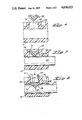
- FIG. 1 is a perspective view of an electrical connector according to the invention with a stuffer member exploded from the connector for clarity;
- FIG. 2 is a perspective view of a first example of stuffer member
- FIG. 4 is a fragmentary cross-sectional view of the rear of the connector taken along line 4-4 of FIG. 1;
Landscapes
- Details Of Connecting Devices For Male And Female Coupling (AREA)
Abstract
Description
Claims (6)
Priority Applications (1)
| Application Number | Priority Date | Filing Date | Title |
|---|---|---|---|
| US06/718,148 US4636023A (en) | 1985-04-01 | 1985-04-01 | Electrical connector with strain relief |
Applications Claiming Priority (1)
| Application Number | Priority Date | Filing Date | Title |
|---|---|---|---|
| US06/718,148 US4636023A (en) | 1985-04-01 | 1985-04-01 | Electrical connector with strain relief |
Publications (1)
| Publication Number | Publication Date |
|---|---|
| US4636023A true US4636023A (en) | 1987-01-13 |
Family
ID=24885011
Family Applications (1)
| Application Number | Title | Priority Date | Filing Date |
|---|---|---|---|
| US06/718,148 Expired - Lifetime US4636023A (en) | 1985-04-01 | 1985-04-01 | Electrical connector with strain relief |
Country Status (1)
| Country | Link |
|---|---|
| US (1) | US4636023A (en) |
Cited By (8)
| Publication number | Priority date | Publication date | Assignee | Title |
|---|---|---|---|---|
| US4887977A (en) * | 1988-06-15 | 1989-12-19 | E. I. Dupont De Nemours And Company | Cable connector haing a resilient cover |
| US5260678A (en) * | 1991-04-04 | 1993-11-09 | Magnetek, Inc. | Fluorescent-lamp leadless ballast with improved connector |
| US5445538A (en) * | 1993-11-17 | 1995-08-29 | Thomas & Betts Corporation | Electrical connector strain relief |
| US5478252A (en) * | 1993-02-10 | 1995-12-26 | Societe Anonyme Dite: Alcatel Cable Interface | Disconnectable male connector for communications networks |
| US5514007A (en) * | 1994-05-04 | 1996-05-07 | Thomas & Betts Corporation | Data connector strain relief assembly |
| WO2004071676A1 (en) * | 2003-02-11 | 2004-08-26 | Concept Express Pty Ltd | A fluid dispensing accessory |
| US20060025006A1 (en) * | 2004-07-29 | 2006-02-02 | David Powell | Cable retaining system |
| US20220278485A1 (en) * | 2021-02-26 | 2022-09-01 | Luxshare Precision Industry Co., Ltd. | Cable securing clamp and data transmission device |
Citations (3)
| Publication number | Priority date | Publication date | Assignee | Title |
|---|---|---|---|---|
| US3103399A (en) * | 1960-12-07 | 1963-09-10 | Ibm | Strain relief device |
| US4160575A (en) * | 1978-02-24 | 1979-07-10 | Vari-Tronics Co. | Telephone cord connector |
| US4211462A (en) * | 1979-01-22 | 1980-07-08 | Stewart Stamping Corporation, A Division Of Insilco Corp. | Electrical connector for termination cords with improved locking means |
-
1985
- 1985-04-01 US US06/718,148 patent/US4636023A/en not_active Expired - Lifetime
Patent Citations (3)
| Publication number | Priority date | Publication date | Assignee | Title |
|---|---|---|---|---|
| US3103399A (en) * | 1960-12-07 | 1963-09-10 | Ibm | Strain relief device |
| US4160575A (en) * | 1978-02-24 | 1979-07-10 | Vari-Tronics Co. | Telephone cord connector |
| US4211462A (en) * | 1979-01-22 | 1980-07-08 | Stewart Stamping Corporation, A Division Of Insilco Corp. | Electrical connector for termination cords with improved locking means |
Cited By (10)
| Publication number | Priority date | Publication date | Assignee | Title |
|---|---|---|---|---|
| US4887977A (en) * | 1988-06-15 | 1989-12-19 | E. I. Dupont De Nemours And Company | Cable connector haing a resilient cover |
| US5260678A (en) * | 1991-04-04 | 1993-11-09 | Magnetek, Inc. | Fluorescent-lamp leadless ballast with improved connector |
| US5350316A (en) * | 1991-04-04 | 1994-09-27 | Magnetek, Inc. | Fluorescent-lamp leadless ballast with improved connector |
| US5478252A (en) * | 1993-02-10 | 1995-12-26 | Societe Anonyme Dite: Alcatel Cable Interface | Disconnectable male connector for communications networks |
| US5445538A (en) * | 1993-11-17 | 1995-08-29 | Thomas & Betts Corporation | Electrical connector strain relief |
| US5514007A (en) * | 1994-05-04 | 1996-05-07 | Thomas & Betts Corporation | Data connector strain relief assembly |
| WO2004071676A1 (en) * | 2003-02-11 | 2004-08-26 | Concept Express Pty Ltd | A fluid dispensing accessory |
| US20060025006A1 (en) * | 2004-07-29 | 2006-02-02 | David Powell | Cable retaining system |
| US20220278485A1 (en) * | 2021-02-26 | 2022-09-01 | Luxshare Precision Industry Co., Ltd. | Cable securing clamp and data transmission device |
| US11509091B2 (en) * | 2021-02-26 | 2022-11-22 | Luxshare Precision Industry Co., Ltd. | Cable securing clamp and data transmission device |
Similar Documents
| Publication | Publication Date | Title |
|---|---|---|
| US4343528A (en) | Modular interconnect system | |
| US3954320A (en) | Electrical connecting devices for terminating cords | |
| US4243288A (en) | Connector assembly for mass termination | |
| CA1068363A (en) | Electrical connector having insulation stripping means | |
| US4934947A (en) | Modular jack for flat flexible cable | |
| US4269466A (en) | Connector and strain relief for flat transmission cable | |
| EP0310339B1 (en) | Field terminable modular connector | |
| EP0542164B1 (en) | An electrical connector arrangement | |
| EP0021731B1 (en) | Electrical contact member and connector including such contact members | |
| US4448471A (en) | Polarized locking latch cover for an electrical connector | |
| US4527852A (en) | Multigauge insulation displacement connector and contacts therefor | |
| CA1063204A (en) | Electrical connector housing for slotted terminal to insulated conductor connection | |
| US4557543A (en) | Key hole retention | |
| EP0751583A3 (en) | Electrical connector with improved conductor retention means | |
| US4435035A (en) | Mass terminatable single row connector assembly | |
| US4653831A (en) | Connector housing | |
| US5402561A (en) | Crimping tool having angularly offset crimping dies | |
| US5409404A (en) | Electrical connector with slotted beam contact | |
| US4636023A (en) | Electrical connector with strain relief | |
| JP3970321B2 (en) | Wire connection system | |
| US4475786A (en) | T Bar cover latch | |
| US4373766A (en) | Electrical connector assembly | |
| US4431249A (en) | Male/female cable connector | |
| CA1069199A (en) | Cam actuated low insertion force connector | |
| US6761576B1 (en) | Insulation displacement contact connector |
Legal Events
| Date | Code | Title | Description |
|---|---|---|---|
| AS | Assignment |
Owner name: AMP INCORPORATED, PO BOX 3608, HARRISBURG, PA. 17 Free format text: ASSIGNMENT OF ASSIGNORS INTEREST.;ASSIGNOR:OLSSON, BILLY E.;REEL/FRAME:004392/0986 Effective date: 19850328 |
|
| STCF | Information on status: patent grant |
Free format text: PATENTED CASE |
|
| FEPP | Fee payment procedure |
Free format text: PAYER NUMBER DE-ASSIGNED (ORIGINAL EVENT CODE: RMPN); ENTITY STATUS OF PATENT OWNER: LARGE ENTITY Free format text: PAYOR NUMBER ASSIGNED (ORIGINAL EVENT CODE: ASPN); ENTITY STATUS OF PATENT OWNER: LARGE ENTITY |
|
| FPAY | Fee payment |
Year of fee payment: 4 |
|
| FEPP | Fee payment procedure |
Free format text: PAYER NUMBER DE-ASSIGNED (ORIGINAL EVENT CODE: RMPN); ENTITY STATUS OF PATENT OWNER: LARGE ENTITY Free format text: PAYOR NUMBER ASSIGNED (ORIGINAL EVENT CODE: ASPN); ENTITY STATUS OF PATENT OWNER: LARGE ENTITY |
|
| FPAY | Fee payment |
Year of fee payment: 8 |
|
| FPAY | Fee payment |
Year of fee payment: 12 |