US4634334A - Vehicle restraint - Google Patents
Vehicle restraint Download PDFInfo
- Publication number
- US4634334A US4634334A US06/757,030 US75703085A US4634334A US 4634334 A US4634334 A US 4634334A US 75703085 A US75703085 A US 75703085A US 4634334 A US4634334 A US 4634334A
- Authority
- US
- United States
- Prior art keywords
- vehicle
- locking device
- releasable locking
- axis
- outwardly
- Prior art date
- Legal status (The legal status is an assumption and is not a legal conclusion. Google has not performed a legal analysis and makes no representation as to the accuracy of the status listed.)
- Expired - Lifetime
Links
- 230000002441 reversible effect Effects 0.000 claims description 2
- 230000000694 effects Effects 0.000 claims 1
- 230000006378 damage Effects 0.000 description 2
- 238000009434 installation Methods 0.000 description 2
- 238000005192 partition Methods 0.000 description 2
- 208000027418 Wounds and injury Diseases 0.000 description 1
- 230000002411 adverse Effects 0.000 description 1
- 238000004873 anchoring Methods 0.000 description 1
- 238000010276 construction Methods 0.000 description 1
- 230000001419 dependent effect Effects 0.000 description 1
- 208000014674 injury Diseases 0.000 description 1
- 230000007257 malfunction Effects 0.000 description 1
- 238000012986 modification Methods 0.000 description 1
- 230000004048 modification Effects 0.000 description 1
- 230000001681 protective effect Effects 0.000 description 1
- 125000006850 spacer group Chemical group 0.000 description 1
- 230000000007 visual effect Effects 0.000 description 1
- XLYOFNOQVPJJNP-UHFFFAOYSA-N water Substances O XLYOFNOQVPJJNP-UHFFFAOYSA-N 0.000 description 1
Images

Classifications
-
- B—PERFORMING OPERATIONS; TRANSPORTING
- B65—CONVEYING; PACKING; STORING; HANDLING THIN OR FILAMENTARY MATERIAL
- B65G—TRANSPORT OR STORAGE DEVICES, e.g. CONVEYORS FOR LOADING OR TIPPING, SHOP CONVEYOR SYSTEMS OR PNEUMATIC TUBE CONVEYORS
- B65G69/00—Auxiliary measures taken, or devices used, in connection with loading or unloading
- B65G69/003—Restraining movement of a vehicle at a loading station using means not being part of the vehicle
Definitions
- Wheel chocks are the most commonly employed because of their simplicity of design; however, they are susceptible to becoming lost or stolen; are ineffective where the roadway surface is slippery due to ice, water or oil drippings; and the proper positioning of the chocks relative to the rear set of wheels is normally the responsibility of the vehicle driver and is dependent upon the diligence and care exercised by the driver.
- prior vehicle restraints require troughs or ditches to be formed in the roadway or require recesses or pockets to be formed in the dock wall in order to accommodate various components of the particular restraint. Thus, the installation costs are inordinately high and require defacement of either the roadway or dock wall. In other instances, some prior vehicle restraints require elaborate controls and various power sources to actuate the restraints which add significantly to the complexity and costs of the restraint. In still other prior vehicle restraints, they are susceptible to malfunction due to certain of the components thereof being exposed and adversely affected by severe climatic conditions.
- a vehicle restraint for securing a parked vehicle adjacent an upright wall of a loading dock.
- the device includes a first means which is mounted adjacent the dock wall and the roadway on which the vehicle is parked.
- the first means projects outwardly from the dock wall.
- a second means is mounted on an outer distal end of the first means for selective movement about an outwardly projecting axis between operative and inoperative modes. When the second means is in an operative mode, at least a portion thereof projects upwardly and assumes a vehicle interlocking position.
- the said portion of the second means assumes a vehicle release position which is disposed at a substantial angle with respect to the vehicle interlocking position and in a non-obstructing relation with respect to the parked vehicle.
- Third means associated with the first means selectively actuates the second means from the inoperative mode to the operative mode.
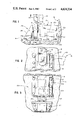
- FIG. 1 is a fragmentary side elevation view of one form of the improved vehicle restraint showing the locking device thereof in a operative mode.
- FIG. 2 is a fragmentary sectional view taken along line 2--2 of FIG. 1.
- FIG. 3 is a fragmentary top view of the restraint shown in FIG. 1.
- FIG. 4 is similar to FIG. 1 but showing a second form of the improved vehicle restraint.
- FIG. 5 is a fragmentary left end view of the restraint of FIG. 4.
- FIG. 6 is similar to FIG. 3 but of the restraint of FIG. 4.
- FIG. 7 is an enlarged perspective exploded view of a modified component of the restraint of FIG. 1.
- FIGS. 8 and 9 are enlarged fragmentary side elevational views of two forms of a component for the restraint of FIG. 4.
- the restraint 20 includes an elongated first member 21 which is provided with a mounting flange 21a secured by a plurality of anchoring bolts 22 to the dock wall W and the roadway R.
- the mounting flange 21a projects outwardly from a protective shroud or housing 21b.
- Rotatably mounted on the outer or distal end portion of the first member 21 is an elongated arm-like second member 23.
- Member 23 is adapted to be actuated by a drive motor M to rotate between an operative mode I and an inoperative mode II, see FIG. 2.
- the drive shaft of the motor is connected to a gear reduction unit U, which in turn is connected by a stub shaft X to the lower end portion of the arm-like member 23.
- the outer end of shaft X is supported in a journal bearing, not shown, formed in a bracket 24 disposed outwardly of member 23, see FIG. 1.
- the spacing Z between the outer end of member 21 and bracket 24 is of such dimension as to allow the lower end portion 23a of member 23 and a pair of spacer washers 25 to fit therebetween.
- Drive motor M is preferably of a reversible type and is connected by suitable wiring V to conventional push-button controls, not shown, which are normally located inside the plant or warehouse provided with the loading dock. Such controls are situated adjacent the doorway served by the loading dock and are under the control of loading dock personnel. Audio and visual warning signals, not shown, are mounted on the exterior of the plant or warehouse to alert the vehicle driver as to whether the restraint is in the operative vehicle-locking mode I or in the inoperative vehicle-release mode II. Similar signals are provided adjacent the push-button controls so as to alert the dock personnel as to when conditions are safe for loading or unloading the parked vehicle.
- First member 21 has a low profile and the upper surface of the shroud 21b has a preferred elevation relative to the roadway of between 10" to 12".
- the arm-like member 23 is set out from the dock wall W approximately 13". Where the vehicle restraint is used in conjunction with a dock leveler or end of dock ramp, neither of which is shown, the distance the member 23 is set out from the dock wall will depend upon the extent to which the lip plate or ramp projects from the wall when it is engaging the bed of the parked vehicle. Normally, the lip plate will project outwardly about 16".
- arm-like member 23 when in an operative mode, will restrain the parked vehicle, during loading and unloading from accidentally or inadvertently moving away from the dock wall an amount which will cause the lip plate or ramp from becoming disengaged from the vehicle bed.
- the dock leveler to which it is connected is unsupported at its outer end causing the deck of the dock leveler to suddently pivot downwardly. If a forklift truck, a cart, the loaded or unloaded product, or dock personnel is disposed on the deck at the time the lip plate or ramp becomes disengaged, serious injury to the personnel and damage to the product and handling equipment will result.
- the length of member 23 may vary as desired, but it is preferred that it project approximately 22"-24" above the top surface of the shroud or housing 21b, when the arm-like member 23 is in the operative mode. It has been found that with most trucks and semi-trailer trucks, the height of the ICC bar B above the roadway will vary from a minimum of about 15" to a maximum of about 30" and will experience a normal float of approximately 2"-3" in either direction during the loading or unloading operation. Because of the low profile of the shroud 21b and the length of arm-like member 23, the problem of float is of no concern as the ICC bar B is free to move vertically relative to member 23 when the latter is in the operative mode I.
- member 23 may be formed of a plurality of interconnected sections A and A', only two being shown in FIG. 7.
- Section A which is connected directly to stub shaft X, has an opening 26 formed in the free end thereof. The free end is accommodated by a bifurcated end 27 of section A' which also is provided with openings 28.
- openings 26 and 28 are in alignment and accommodate a connecting pin 30.
- the sections A and A' are adapted to normally assume a straight-line or aligned relation by one or more biasing springs 31.
- the section A' of member 23 may pivot in either direction relative to section A, if section A' should meet an obstruction and thus, permit section A to continue its pivotal movement to the desired mode.
- the pivot axis between sections A and A', defined by connecting pin 30, is substantially parallel to the pivot axis of member 23, defined by stub shaft X. Both axes are perpendicular to the dock wall W and thus, the sections A and A' will not pivot relative to one another when subjected to an outward, pulling force by the entrapped ICC bar B.
- the number and shape of the sections comprising the member 23 may vary from that shown, if desired.
- Restraint 120 includes an elongated, low profile, first member 121 which is secured to the dock wall W and roadway R by a plurality of anchor bolts 122.
- Member 121 includes a shroud or housing 121a, the height and length dimensions of which are substantially the same as those of shroud 21a; namely 10"-12" height and approximately 13" length.
- An L-shaped second member 123 is provided which is supported by the first member 121 and is adapted to pivot about one leg Q thereof as an axis between operative and inoperative modes.
- the second leg Y of member 123 projects laterally from the outer end of member 121, see FIG. 4.
- a drive motor M' Disposed within shroud 121a of member 121 is a drive motor M' which has the drive shaft thereof in meshing engagement with a gear G carried on the leg Q of the L-shaped member 123.
- the gear G is disposed within shroud 121a and is located between a pair of support bearings 150 and 151.
- Bearing 150 is mounted within an opening formed in an upright partition 152 which in turn is disposed in spaced substantially parallel proximate relation with respect to dock wall W.
- Bearing 151 is mounted within an opening formed in the end wall 121c of shroud 121.
- the inner end of the leg Q of member 123 has affixed thereto an enlarged end piece 153 which is disposed between partition 152 and the dock wall W.
- the end piece 153 may comprise a washer or collar K which is held in place on the leg Q by a lock nut or bolt N, see FIGS. 8 and 9.
- the L-shaped member 123 shown in FIG. 8 is substantially the same configuration as member 123, shown in FIG. 9 except in the latter version splines S in the leg Q have been substituted for the gear G. Accordingly, a worm gear, not shown, connected to the drive shaft of motor M' meshes with the splines so as to control the rotation of leg Y about leg Q as an axis.
- the Y leg of member 123 may comprise a plurality of sections, not shown, which are pivotally connected to one another in a manner similar to that shown in FIG. 7.
- the member 23 or 123 When the member 23 or 123 is in an operative mode, it assumes a vertical or 12 o'clock position and, when it is in an inoperative mode, it assumes a substantially horizontal or 3 o'clock position or a downwardly inclined position, so that the member 23 or 123 will not obstruct movement of the vehicle toward or away from the dock wall W.
- first member 21 or 121 is shown anchored to both the roadway and dock wall, attachment to only one of these surfaces may be sufficient in some installations.
- an improved vehicle restraint which is of simple, yet sturdy construction, is easy to install and can be utilized with or without a dock leveler. Furthermore, the improved vehicle restraint can readily accommodate trucks or trailers where the ICC bars thereof may vary in height and location over a wide range. Because of the shroud or housing having a low profile and the effective length of the arm-like member being substantial, the matter of float of the ICC bar during loading and unloading operation is of no concern.
- the improved vehicle restraint when in the inoperative mode, is not susceptible to being struck by a backing truck or trailer.
- the shroud 21 or 121 provides protection for the motor and gears against snow, ice, dirt and debris.
- the improved vehicle restraint does not interfere with any of the dock leveler components when the dock leveler is disposed in a below level position during end loading or unloading of the vehicle.
Landscapes
- Engineering & Computer Science (AREA)
- Mechanical Engineering (AREA)
- Auxiliary Methods And Devices For Loading And Unloading (AREA)
Abstract
Description
Claims (10)
Priority Applications (1)
| Application Number | Priority Date | Filing Date | Title |
|---|---|---|---|
| US06/757,030 US4634334A (en) | 1985-07-19 | 1985-07-19 | Vehicle restraint |
Applications Claiming Priority (1)
| Application Number | Priority Date | Filing Date | Title |
|---|---|---|---|
| US06/757,030 US4634334A (en) | 1985-07-19 | 1985-07-19 | Vehicle restraint |
Publications (1)
| Publication Number | Publication Date |
|---|---|
| US4634334A true US4634334A (en) | 1987-01-06 |
Family
ID=25046066
Family Applications (1)
| Application Number | Title | Priority Date | Filing Date |
|---|---|---|---|
| US06/757,030 Expired - Lifetime US4634334A (en) | 1985-07-19 | 1985-07-19 | Vehicle restraint |
Country Status (1)
| Country | Link |
|---|---|
| US (1) | US4634334A (en) |
Cited By (50)
| Publication number | Priority date | Publication date | Assignee | Title |
|---|---|---|---|---|
| US4695216A (en) * | 1986-05-14 | 1987-09-22 | Kelley Company, Inc. | Vehicle restraint |
| US4735542A (en) * | 1986-05-07 | 1988-04-05 | Nova Technology, Inc. | Truck restraint |
| US4759678A (en) * | 1986-09-08 | 1988-07-26 | Kelley Company Inc. | Vehicle restraint utilizing a fluid cylinder |
| US4815918A (en) * | 1987-08-21 | 1989-03-28 | Kelley Company, Inc. | Vehicle restraint having a snubbing restraining member |
| US4861217A (en) * | 1987-02-17 | 1989-08-29 | Kelley Company, Inc. | Vehicle restraint using both linear and pivotal movement |
| US4865508A (en) * | 1987-05-21 | 1989-09-12 | Kelley Company Inc. | Vehicle restraint |
| US4887954A (en) * | 1989-03-09 | 1989-12-19 | Air-Lec Industries, Inc. | Vehicle restraint |
| US4938648A (en) * | 1988-08-31 | 1990-07-03 | General Motors Corporation | Shipping dock hook |
| US4938647A (en) * | 1989-09-21 | 1990-07-03 | Kelley Company Inc. | Truck actuated vehicle restraint having a pivotable slide |
| US4973213A (en) * | 1989-09-21 | 1990-11-27 | Kelley Company Inc. | Truck actuated vehicle restraint having a pivotable inclined surface |
| US5203663A (en) * | 1991-05-23 | 1993-04-20 | Dock Leveler Manufacturing, Inc. | Vehicle restraining mechanism |
| US5259718A (en) * | 1990-01-18 | 1993-11-09 | The Serco Corporation | Vehicle restraint |
| USD349229S (en) | 1992-12-28 | 1994-08-02 | Blue Giant Equipment Corporation | Restraint latch for trucks |
| US5348437A (en) * | 1993-05-17 | 1994-09-20 | Overhead Door Corporation | Vehicle restraining apparatus |
| US5375965A (en) * | 1993-01-25 | 1994-12-27 | Rite-Hite Corporation | Vehicle restraining device |
| US5452489A (en) * | 1993-09-21 | 1995-09-26 | Systems, Inc. | Dock leveler with automatic end barrier |
| US5457838A (en) * | 1993-09-21 | 1995-10-17 | Systems, Inc. | Extendible dock leveler |
| US5553987A (en) * | 1994-03-07 | 1996-09-10 | Rite-Hite Corporation | Truck activated wheel chocking device |
| US5582498A (en) * | 1994-10-21 | 1996-12-10 | Rite-Hite Corporation | Wheel activated vehicle restraint |
| US5683219A (en) * | 1996-06-07 | 1997-11-04 | Pioneer Manufacturing, Inc. | Mechanical truck restraint |
| US5702223A (en) * | 1993-12-23 | 1997-12-30 | Rite-Hite Corporation | Vehicle restraint |
| US5762459A (en) * | 1994-10-21 | 1998-06-09 | Rite-Hite Corporation | Wheel-activated vehicle restraint system |
| US6010297A (en) * | 1996-09-03 | 2000-01-04 | Rite-Hite Holding Corporation | Vehicle restraint and improvements |
| US6190108B1 (en) * | 1990-01-18 | 2001-02-20 | The Serco Corporation | Vehicle restraint |
| US6318947B1 (en) | 1999-01-22 | 2001-11-20 | Rite-Hite Holding Corporation | Pulling-style restraint for a parked swap body |
| US20030170097A1 (en) * | 2002-01-31 | 2003-09-11 | Paul Pedersen | Truck restraint |
| US6726432B2 (en) | 2001-09-13 | 2004-04-27 | Rite-Hite Holding Corporation | Low-profile vehicle restraint |
| US6773221B2 (en) | 2001-07-05 | 2004-08-10 | Rite-Hite Holding Corporation | Positive locking mechanism for a wheel-activated vehicle restraint |
| US20040177456A1 (en) * | 2003-03-12 | 2004-09-16 | Hoofard Richard K. | Support leg system and method for supporting a dock leveler |
| US20040177455A1 (en) * | 2003-03-12 | 2004-09-16 | Kelley Company, Inc. | Support leg system and method for supporting a dock leveler |
| US20050169732A1 (en) * | 2003-12-22 | 2005-08-04 | Matt Sveum | Brace system and method for a vehicle at a loading dock |
| US20050196255A1 (en) * | 2003-12-22 | 2005-09-08 | Matt Sveum | Yieldable brace for a vehicle at a loading dock |
| US7062813B2 (en) | 2003-03-12 | 2006-06-20 | Spx Dock Products, Inc. | Support leg system and method for supporting a dock leveler |
| US7249926B1 (en) * | 2004-09-15 | 2007-07-31 | Nova Technology International, Llc | Driveway truck restraint |
| US20070248440A1 (en) * | 2003-12-22 | 2007-10-25 | Rite-Hite Holding Corporation | Yieldable brace for a vehicle at a loading dock |
| US20090026022A1 (en) * | 2007-07-25 | 2009-01-29 | Rite-Hite Holding Corporation | Wheel chock system |
| US20090223764A1 (en) * | 2008-03-04 | 2009-09-10 | Jonathan Andersen | Restraining arms for wheel chocks |
| US20090283999A1 (en) * | 2008-05-13 | 2009-11-19 | Jonathan Andersen | Support frame vehicle restraints |
| US20110172875A1 (en) * | 2010-01-14 | 2011-07-14 | Cls International | Transport system |
| US8006811B2 (en) | 2007-09-07 | 2011-08-30 | Rite-Hite Holding Corporation | Loading dock wheel restraint comprising a flexible elongate member |
| US8286757B2 (en) | 2010-07-09 | 2012-10-16 | Rite-Hite Holding Corporation | Wheel chock system |
| US9751702B1 (en) | 2016-06-06 | 2017-09-05 | ASSA ABLOY Entrance Systems, Inc. | Wheel chock systems |
| US9896282B2 (en) | 2016-05-27 | 2018-02-20 | Rite-Hite Holding Corporation | Pedestrian-vehicle warning systems for loading docks |
| US10329104B2 (en) | 2016-04-04 | 2019-06-25 | Assa Abloy Entrance Systems Ab | Vehicle restraint |
| US10745220B2 (en) | 2017-06-28 | 2020-08-18 | Systems, LLC | Vehicle Restraint System |
| US10781062B2 (en) | 2015-11-24 | 2020-09-22 | Systems, LLC | Vehicle restraint system |
| US10906759B2 (en) | 2017-06-28 | 2021-02-02 | Systems, LLC | Loading dock vehicle restraint system |
| US10988329B2 (en) | 2019-02-15 | 2021-04-27 | Assa Abloy Entrance Systems Ab | Vehicle restraint |
| US11618642B2 (en) | 2020-08-20 | 2023-04-04 | Assa Abloy Entrance Systems Ab | Vehicle restraint systems and methods |
| WO2024156707A1 (en) | 2023-01-27 | 2024-08-02 | Assa Abloy Entrance Systems Ab | Vehicle restraint |
Citations (7)
| Publication number | Priority date | Publication date | Assignee | Title |
|---|---|---|---|---|
| US4208161A (en) * | 1978-05-30 | 1980-06-17 | Rite-Hite Corporation | Device for releasably securing a vehicle to an adjacent support |
| US4264259A (en) * | 1979-09-06 | 1981-04-28 | Rite-Hite Corporation | Releasable locking device |
| US4282621A (en) * | 1978-12-11 | 1981-08-11 | Rite-Hite Corporation | Releasable locking device |
| US4373847A (en) * | 1981-05-04 | 1983-02-15 | Rite-Hite Corporation | Releasable locking device |
| US4443150A (en) * | 1981-11-13 | 1984-04-17 | Rite-Hite Corporation | Releasable locking device |
| US4555211A (en) * | 1982-06-11 | 1985-11-26 | Metz Donald L | Truck locking device |
| US4589813A (en) * | 1984-06-07 | 1986-05-20 | Hagen James P | Truck restraining device |
-
1985
- 1985-07-19 US US06/757,030 patent/US4634334A/en not_active Expired - Lifetime
Patent Citations (7)
| Publication number | Priority date | Publication date | Assignee | Title |
|---|---|---|---|---|
| US4208161A (en) * | 1978-05-30 | 1980-06-17 | Rite-Hite Corporation | Device for releasably securing a vehicle to an adjacent support |
| US4282621A (en) * | 1978-12-11 | 1981-08-11 | Rite-Hite Corporation | Releasable locking device |
| US4264259A (en) * | 1979-09-06 | 1981-04-28 | Rite-Hite Corporation | Releasable locking device |
| US4373847A (en) * | 1981-05-04 | 1983-02-15 | Rite-Hite Corporation | Releasable locking device |
| US4443150A (en) * | 1981-11-13 | 1984-04-17 | Rite-Hite Corporation | Releasable locking device |
| US4555211A (en) * | 1982-06-11 | 1985-11-26 | Metz Donald L | Truck locking device |
| US4589813A (en) * | 1984-06-07 | 1986-05-20 | Hagen James P | Truck restraining device |
Cited By (75)
| Publication number | Priority date | Publication date | Assignee | Title |
|---|---|---|---|---|
| US4735542A (en) * | 1986-05-07 | 1988-04-05 | Nova Technology, Inc. | Truck restraint |
| US4695216A (en) * | 1986-05-14 | 1987-09-22 | Kelley Company, Inc. | Vehicle restraint |
| US4759678A (en) * | 1986-09-08 | 1988-07-26 | Kelley Company Inc. | Vehicle restraint utilizing a fluid cylinder |
| US4861217A (en) * | 1987-02-17 | 1989-08-29 | Kelley Company, Inc. | Vehicle restraint using both linear and pivotal movement |
| US4865508A (en) * | 1987-05-21 | 1989-09-12 | Kelley Company Inc. | Vehicle restraint |
| US4815918A (en) * | 1987-08-21 | 1989-03-28 | Kelley Company, Inc. | Vehicle restraint having a snubbing restraining member |
| US4938648A (en) * | 1988-08-31 | 1990-07-03 | General Motors Corporation | Shipping dock hook |
| US4887954A (en) * | 1989-03-09 | 1989-12-19 | Air-Lec Industries, Inc. | Vehicle restraint |
| US4973213A (en) * | 1989-09-21 | 1990-11-27 | Kelley Company Inc. | Truck actuated vehicle restraint having a pivotable inclined surface |
| US4938647A (en) * | 1989-09-21 | 1990-07-03 | Kelley Company Inc. | Truck actuated vehicle restraint having a pivotable slide |
| US6190108B1 (en) * | 1990-01-18 | 2001-02-20 | The Serco Corporation | Vehicle restraint |
| US5259718A (en) * | 1990-01-18 | 1993-11-09 | The Serco Corporation | Vehicle restraint |
| US5203663A (en) * | 1991-05-23 | 1993-04-20 | Dock Leveler Manufacturing, Inc. | Vehicle restraining mechanism |
| USD349229S (en) | 1992-12-28 | 1994-08-02 | Blue Giant Equipment Corporation | Restraint latch for trucks |
| US6676360B2 (en) | 1993-01-25 | 2004-01-13 | Rite-Hite Holding Corporation | Vehicle restraining device |
| US5375965A (en) * | 1993-01-25 | 1994-12-27 | Rite-Hite Corporation | Vehicle restraining device |
| US6238163B1 (en) | 1993-01-25 | 2001-05-29 | Rite-Hite Holding Corporation | Vehicle restraining device |
| US5348437A (en) * | 1993-05-17 | 1994-09-20 | Overhead Door Corporation | Vehicle restraining apparatus |
| US5452489A (en) * | 1993-09-21 | 1995-09-26 | Systems, Inc. | Dock leveler with automatic end barrier |
| US5457838A (en) * | 1993-09-21 | 1995-10-17 | Systems, Inc. | Extendible dock leveler |
| US5702223A (en) * | 1993-12-23 | 1997-12-30 | Rite-Hite Corporation | Vehicle restraint |
| US5964572A (en) * | 1993-12-23 | 1999-10-12 | Rite-Hite Holding Corporation | Vehicle restraint |
| US5553987A (en) * | 1994-03-07 | 1996-09-10 | Rite-Hite Corporation | Truck activated wheel chocking device |
| US5664930A (en) * | 1994-03-07 | 1997-09-09 | Rite-Hite Corporation | Vehicle activated wheel chock positioning device |
| US5582498A (en) * | 1994-10-21 | 1996-12-10 | Rite-Hite Corporation | Wheel activated vehicle restraint |
| US5762459A (en) * | 1994-10-21 | 1998-06-09 | Rite-Hite Corporation | Wheel-activated vehicle restraint system |
| USRE37570E1 (en) | 1994-10-21 | 2002-03-05 | Rite-Hite Holding Corporation | Wheel-activated vehicle restraint system |
| US5683219A (en) * | 1996-06-07 | 1997-11-04 | Pioneer Manufacturing, Inc. | Mechanical truck restraint |
| US6074157A (en) * | 1996-09-03 | 2000-06-13 | Rite-Hite Holding Corporation | Vehicle restraint and improvements |
| US6010297A (en) * | 1996-09-03 | 2000-01-04 | Rite-Hite Holding Corporation | Vehicle restraint and improvements |
| US6220809B1 (en) | 1996-09-03 | 2001-04-24 | Rite-Hite Holding Corporation | Vehicle restraint and improvements |
| US6318947B1 (en) | 1999-01-22 | 2001-11-20 | Rite-Hite Holding Corporation | Pulling-style restraint for a parked swap body |
| US6773221B2 (en) | 2001-07-05 | 2004-08-10 | Rite-Hite Holding Corporation | Positive locking mechanism for a wheel-activated vehicle restraint |
| US6726432B2 (en) | 2001-09-13 | 2004-04-27 | Rite-Hite Holding Corporation | Low-profile vehicle restraint |
| US20030170097A1 (en) * | 2002-01-31 | 2003-09-11 | Paul Pedersen | Truck restraint |
| US7056077B2 (en) * | 2002-01-31 | 2006-06-06 | Pentalift Equipment Corporation | Truck restraint |
| US20040177455A1 (en) * | 2003-03-12 | 2004-09-16 | Kelley Company, Inc. | Support leg system and method for supporting a dock leveler |
| US20060137114A1 (en) * | 2003-03-12 | 2006-06-29 | Hoofard Richard K | Support leg system and method for supporting a dock leveler |
| US6931686B2 (en) | 2003-03-12 | 2005-08-23 | Spx Dock Products Inc. | Support leg system and method for supporting a dock leveler |
| US7225493B2 (en) | 2003-03-12 | 2007-06-05 | 4 Front Engineered Solutions, Inc. | Support leg system and method for supporting a dock leveler |
| US7047584B2 (en) | 2003-03-12 | 2006-05-23 | Spx Dock Products, Inc. | Support leg system and method for supporting a dock leveler |
| US20040177456A1 (en) * | 2003-03-12 | 2004-09-16 | Hoofard Richard K. | Support leg system and method for supporting a dock leveler |
| US7062813B2 (en) | 2003-03-12 | 2006-06-20 | Spx Dock Products, Inc. | Support leg system and method for supporting a dock leveler |
| US7216392B2 (en) | 2003-03-12 | 2007-05-15 | Spx Dock Products, Inc. | Support leg system and method for supporting a dock leveler |
| US20060207040A1 (en) * | 2003-03-12 | 2006-09-21 | Hoofard Richard K | Support leg system and method for supporting a dock leveler |
| US20050169732A1 (en) * | 2003-12-22 | 2005-08-04 | Matt Sveum | Brace system and method for a vehicle at a loading dock |
| US20050196255A1 (en) * | 2003-12-22 | 2005-09-08 | Matt Sveum | Yieldable brace for a vehicle at a loading dock |
| US20070248440A1 (en) * | 2003-12-22 | 2007-10-25 | Rite-Hite Holding Corporation | Yieldable brace for a vehicle at a loading dock |
| US8657551B2 (en) | 2003-12-22 | 2014-02-25 | Rite-Hite Holding Corporation | Yieldable brace for a vehicle at a loading dock |
| US7249926B1 (en) * | 2004-09-15 | 2007-07-31 | Nova Technology International, Llc | Driveway truck restraint |
| US20090026022A1 (en) * | 2007-07-25 | 2009-01-29 | Rite-Hite Holding Corporation | Wheel chock system |
| US8307956B2 (en) | 2007-07-25 | 2012-11-13 | Rite-Hite Holding Corporation | Wheel chock system |
| US8006811B2 (en) | 2007-09-07 | 2011-08-30 | Rite-Hite Holding Corporation | Loading dock wheel restraint comprising a flexible elongate member |
| US8464846B2 (en) | 2008-03-04 | 2013-06-18 | Rite-Hite Holding Corporation | Restraining arms for wheel chocks |
| US20090223764A1 (en) * | 2008-03-04 | 2009-09-10 | Jonathan Andersen | Restraining arms for wheel chocks |
| US20110176896A1 (en) * | 2008-05-13 | 2011-07-21 | Jonathan Andersen | Support frame vehicle restraints |
| US7914042B2 (en) | 2008-05-13 | 2011-03-29 | Rite-Hite Holding Corporation | Support frame vehicle restraints |
| US20090283999A1 (en) * | 2008-05-13 | 2009-11-19 | Jonathan Andersen | Support frame vehicle restraints |
| US8662535B2 (en) | 2008-05-13 | 2014-03-04 | Rite-Hite Holding Corporation | Support frame vehicle restraints |
| US20110172875A1 (en) * | 2010-01-14 | 2011-07-14 | Cls International | Transport system |
| US8942884B2 (en) * | 2010-01-14 | 2015-01-27 | Innovative Transport Solutions, Llc | Transport system |
| US8286757B2 (en) | 2010-07-09 | 2012-10-16 | Rite-Hite Holding Corporation | Wheel chock system |
| US10781062B2 (en) | 2015-11-24 | 2020-09-22 | Systems, LLC | Vehicle restraint system |
| US11465865B2 (en) | 2015-11-24 | 2022-10-11 | Systems, LLC | Vehicle restraint system |
| US10329104B2 (en) | 2016-04-04 | 2019-06-25 | Assa Abloy Entrance Systems Ab | Vehicle restraint |
| US9896282B2 (en) | 2016-05-27 | 2018-02-20 | Rite-Hite Holding Corporation | Pedestrian-vehicle warning systems for loading docks |
| US10392205B2 (en) | 2016-05-27 | 2019-08-27 | Rite-Hite Holding Corporation | Pedestrian-vehicle warning systems for loading docks |
| US10329105B2 (en) | 2016-06-06 | 2019-06-25 | Assa Abloy Entrance Systems Ab | Wheel chock systems |
| US9751702B1 (en) | 2016-06-06 | 2017-09-05 | ASSA ABLOY Entrance Systems, Inc. | Wheel chock systems |
| US10745220B2 (en) | 2017-06-28 | 2020-08-18 | Systems, LLC | Vehicle Restraint System |
| US10906759B2 (en) | 2017-06-28 | 2021-02-02 | Systems, LLC | Loading dock vehicle restraint system |
| US10988329B2 (en) | 2019-02-15 | 2021-04-27 | Assa Abloy Entrance Systems Ab | Vehicle restraint |
| US11618642B2 (en) | 2020-08-20 | 2023-04-04 | Assa Abloy Entrance Systems Ab | Vehicle restraint systems and methods |
| WO2024156707A1 (en) | 2023-01-27 | 2024-08-02 | Assa Abloy Entrance Systems Ab | Vehicle restraint |
| US12503324B2 (en) | 2023-01-27 | 2025-12-23 | Assa Abloy Entrance Systems Ab | Vehicle restraint |
Similar Documents
| Publication | Publication Date | Title |
|---|---|---|
| US4634334A (en) | Vehicle restraint | |
| US4605353A (en) | Vehicle restraint | |
| EP0911285B1 (en) | Vehicle restraining device | |
| EP0012386B1 (en) | A releasable locking device | |
| US4264259A (en) | Releasable locking device | |
| US4443150A (en) | Releasable locking device | |
| US4379354A (en) | Releasable locking device | |
| US5882167A (en) | Locking mechanism for a vehicle restraint | |
| US4589813A (en) | Truck restraining device | |
| US5934857A (en) | Automatic wheel chock system | |
| US4472099A (en) | Releasable locking device | |
| US4208161A (en) | Device for releasably securing a vehicle to an adjacent support | |
| US5249905A (en) | Automatic wheel chocking apparatus having an improved drive mechanism | |
| US4695216A (en) | Vehicle restraint | |
| CA2693477C (en) | Wheel chock system | |
| US4613155A (en) | Safety platform assembly for sanding trucks | |
| CA1317745C (en) | Dock leveler assembly and latching mechanism therefor | |
| CA2272807C (en) | Slope extension for vehicle restraints | |
| USRE33154E (en) | Vehicle restraint | |
| US5683219A (en) | Mechanical truck restraint | |
| EP0522072B1 (en) | Arrangement on a vehicle | |
| US4176825A (en) | Jack device for trailers | |
| JP2001123695A (en) | Powered wheel stopper | |
| US4016990A (en) | Rotatable dock | |
| AU2007266310B2 (en) | Safety system for a transport vehicle |
Legal Events
| Date | Code | Title | Description |
|---|---|---|---|
| AS | Assignment |
Owner name: RITE-HITE CORPORATION MILWAUKEE, WI A CORP. OF WI. Free format text: ASSIGNMENT OF ASSIGNORS INTEREST.;ASSIGNORS:HAHN, NORBERT;OLSON, ARTHUR A. JR.;REEL/FRAME:004434/0328;SIGNING DATES FROM 19850717 TO 19850719 |
|
| STCF | Information on status: patent grant |
Free format text: PATENTED CASE |
|
| AS | Assignment |
Owner name: ABON CORPORATION, A DE CORP. Free format text: MERGER;ASSIGNOR:RITE-HITE CORPORATION, A WI CORP.;REEL/FRAME:004930/0968 Effective date: 19860909 |
|
| FEPP | Fee payment procedure |
Free format text: PAYOR NUMBER ASSIGNED (ORIGINAL EVENT CODE: ASPN); ENTITY STATUS OF PATENT OWNER: LARGE ENTITY |
|
| FPAY | Fee payment |
Year of fee payment: 4 |
|
| SULP | Surcharge for late payment | ||
| FEPP | Fee payment procedure |
Free format text: PAYER NUMBER DE-ASSIGNED (ORIGINAL EVENT CODE: RMPN); ENTITY STATUS OF PATENT OWNER: LARGE ENTITY Free format text: PAYOR NUMBER ASSIGNED (ORIGINAL EVENT CODE: ASPN); ENTITY STATUS OF PATENT OWNER: LARGE ENTITY |
|
| FPAY | Fee payment |
Year of fee payment: 8 |
|
| AS | Assignment |
Owner name: RITE-HITE HOLDING CORPORATION, WISCONSIN Free format text: ASSIGNMENT OF ASSIGNORS INTEREST;ASSIGNOR:RITE-HITE CORPORATION;REEL/FRAME:009207/0712 Effective date: 19971231 |
|
| FPAY | Fee payment |
Year of fee payment: 12 |
|
| FEPP | Fee payment procedure |
Free format text: PAYER NUMBER DE-ASSIGNED (ORIGINAL EVENT CODE: RMPN); ENTITY STATUS OF PATENT OWNER: LARGE ENTITY Free format text: PAYOR NUMBER ASSIGNED (ORIGINAL EVENT CODE: ASPN); ENTITY STATUS OF PATENT OWNER: LARGE ENTITY |