US4631953A - Tubing string testing device - Google Patents
Tubing string testing device Download PDFInfo
- Publication number
- US4631953A US4631953A US06/836,348 US83634886A US4631953A US 4631953 A US4631953 A US 4631953A US 83634886 A US83634886 A US 83634886A US 4631953 A US4631953 A US 4631953A
- Authority
- US
- United States
- Prior art keywords
- separate
- tool
- elements
- tubing string
- fluid passage
- Prior art date
- Legal status (The legal status is an assumption and is not a legal conclusion. Google has not performed a legal analysis and makes no representation as to the accuracy of the status listed.)
- Expired - Lifetime
Links
- 238000012360 testing method Methods 0.000 title claims abstract description 84
- 239000012530 fluid Substances 0.000 claims abstract description 54
- 238000007789 sealing Methods 0.000 claims abstract description 41
- 230000000712 assembly Effects 0.000 claims abstract description 22
- 238000000429 assembly Methods 0.000 claims abstract description 22
- 230000008878 coupling Effects 0.000 claims description 20
- 238000010168 coupling process Methods 0.000 claims description 20
- 238000005859 coupling reaction Methods 0.000 claims description 20
- XLYOFNOQVPJJNP-UHFFFAOYSA-N water Substances O XLYOFNOQVPJJNP-UHFFFAOYSA-N 0.000 claims description 18
- 230000013011 mating Effects 0.000 claims description 6
- 239000007789 gas Substances 0.000 description 18
- 238000013459 approach Methods 0.000 description 3
- 238000000034 method Methods 0.000 description 3
- IJGRMHOSHXDMSA-UHFFFAOYSA-N Atomic nitrogen Chemical compound N#N IJGRMHOSHXDMSA-UHFFFAOYSA-N 0.000 description 2
- 230000006835 compression Effects 0.000 description 2
- 238000007906 compression Methods 0.000 description 2
- 238000010276 construction Methods 0.000 description 2
- 238000003780 insertion Methods 0.000 description 2
- 230000037431 insertion Effects 0.000 description 2
- 239000007788 liquid Substances 0.000 description 2
- 239000000463 material Substances 0.000 description 2
- 238000000926 separation method Methods 0.000 description 2
- 239000004606 Fillers/Extenders Substances 0.000 description 1
- 229910000831 Steel Inorganic materials 0.000 description 1
- 230000000295 complement effect Effects 0.000 description 1
- 238000013461 design Methods 0.000 description 1
- 238000011161 development Methods 0.000 description 1
- 230000018109 developmental process Effects 0.000 description 1
- 230000009977 dual effect Effects 0.000 description 1
- 238000004519 manufacturing process Methods 0.000 description 1
- 239000000203 mixture Substances 0.000 description 1
- 238000012986 modification Methods 0.000 description 1
- 230000004048 modification Effects 0.000 description 1
- 238000012544 monitoring process Methods 0.000 description 1
- 229910052757 nitrogen Inorganic materials 0.000 description 1
- 238000012856 packing Methods 0.000 description 1
- 239000010959 steel Substances 0.000 description 1
Images


Classifications
-
- G—PHYSICS
- G01—MEASURING; TESTING
- G01M—TESTING STATIC OR DYNAMIC BALANCE OF MACHINES OR STRUCTURES; TESTING OF STRUCTURES OR APPARATUS, NOT OTHERWISE PROVIDED FOR
- G01M3/00—Investigating fluid-tightness of structures
- G01M3/02—Investigating fluid-tightness of structures by using fluid or vacuum
- G01M3/26—Investigating fluid-tightness of structures by using fluid or vacuum by measuring rate of loss or gain of fluid, e.g. by pressure-responsive devices, by flow detectors
- G01M3/28—Investigating fluid-tightness of structures by using fluid or vacuum by measuring rate of loss or gain of fluid, e.g. by pressure-responsive devices, by flow detectors for pipes, cables or tubes; for pipe joints or seals; for valves ; for welds
- G01M3/2853—Investigating fluid-tightness of structures by using fluid or vacuum by measuring rate of loss or gain of fluid, e.g. by pressure-responsive devices, by flow detectors for pipes, cables or tubes; for pipe joints or seals; for valves ; for welds for pipe joints or seals
Definitions
- the present invention relates to the method and apparatus for testing the integrity of the walls and connecting joints of a tubing string to determine the presence of leaks in the pipe walls or joints prior to insertion into a bore hole.
- the testing tool itself is normally either supported from a cable and inserted into and removed from the tubing between each test, or is allowed to ride within the tubing sections being formed and is pulled upwardly from a lower section that has been tested into a new section mounted on the previous section in order to check the new upper section.
- Each shows a type of tubing testing apparatus that includes a single passageway for use with a single testing fluid or liquid and will provide only limited testing capability.
- the short tool would normally be five to ten feet in length and gas would be supplied to the small tool normally through flexible hoses that remained connected to the tool. Such hoses and the tool would be lowered into the tubing together with whatever apparatus was used to support the tool during its insertion and removal.
- the longer section would be able to test a pipe having a length of about 25-30 feet, and again the water would be supplied through hoses that remained connected to the longer tool.
- a device for testing the joint area is shown in Loomis U.S. Pat. No. 3,154,940 and for the wall sections of the pipe in Loomis U.S. Pat. No. 3,165,919.
- testing devices that employed one or two passageways and could test only relatively short pipe sections or a single joint and one length of pipe at a time. They were not capable of testing a multiple number of pipe and joint sections along a relatively long tubing string.
- Hailey U.S. Pat. No. 4,519,238, the problem of how to create longer testing tools was addressed.
- a single longitudinal fluid passageway was used to provide the fluid for setting spaced-apart packers along the tool and to also simultaneously provide the fluid used for testing pipe wall sections.
- a second longitudinal fluid passageway system provided a second fluid for testing the integrity of pipe joint areas. While Hailey stated that any number of such fluid passages may be provided, including one such passageway for each test chamber in each packer; Hailey also recognized that there were space availability problems for such passageways, as well as connection difficulties which practically limited the number of passageways which could be conveniently used. In another embodiment, Hailey used three internal fluid passageways.
- the first extended the length of the pipe testing tool and provided pressurized fluid that would set all of the packers and also the fluid necessary for performing controlled tests for certain pipe wall segments.
- a second passageway extended along a portion of the tool provided a source of pressurized gas that would be directed to joint areas bracketed by the tool that could be separately sealed by packers or seals actuated by the first fluid passageway system.
- the third fluid passageway extended only from the head end of the tool down into the first annular chamber formed below the uppermost packer or seal. Accordingly, the third passageway was designed to only test one annular chamber. Any other wall sections would be tested by the fluid used to set the packers.
- the second port included a restriction or orifice which only allowed pressurized fluid to pass into the annular testing cavity after the packer seals were set, presuming they were quick enough. It was believed that such an approach would assume that the packers would be expanded and fully sealed prior to allowing fluid to enter the annular testing chamber defined between two packers. The problem, however, was that the restriction always remained in the line extending back into the first passageway system and also restricted the decrease in pressure within the annular chamber. Thus, if the seals failed, the restriction would prevent fast depressurization of the annular chamber via the internal cavities and the tool leaving a greater pressure in the annular chamber. Occasionally, tools of this nature could fly out of the tubing string.
- testing tools The available space within testing tools is extremely limited and makes it very difficult to appropriately design a tool that will have a sufficient number of fluid passageways to develop precise control over test conditions and a connection system that will permit the passageways to extend along the entire length of the tool.
- the string testing tool contemplated by this invention is for testing double or triple sections of pipes and connecting joints without having to remove the tool after each section is tested. Also, the tool is to have each of the fluid systems operating along the length of the tool with each being totally isolated one from the other.
- the tool has a head section at the top end including a conventional spear portion that can be grappled by a conventional grappling device in order to elevate the tool from a previously tested string section upwardly into a new pipe section made up thereabove.
- the head section also includes a male portion connecting area as well as a mounting collar in the form of a tubular sleeve that can be placed over the male section in order to supply the three fluids under pressure to the tool.
- the bottom end of the tool is provided with a suitable conventional anchor that will allow the tool to be raised vertically, but prevent the tool from dropping downwardly within the pipe string being tested.
- the intermediate portions of the tool are comprised of a mixture of modified separateable tool elements including a bar extension, a sealing assembly, bar members, bar adapter elements and connection element sections.
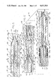
- FIG. 1 is a diagrammatic side elevational view of a tubing string testing tool in accord with the present invention with the sections thereof being interconnected as shown by the dot-dash line;
- FIG. 2 is a cross-section of the head end of the tool
- FIG. 3 is a cross-section of FIG. 2 taken along lines 3--3 thereof;
- FIG. 4 is a cross-sectional view taken along lines 4--4 of FIG. 2;
- FIG. 5 is a cross-sectional view of a bar extension portion of the tool
- FIG. 6 is a cross-sectional view of the packer assembly portion of the tool
- FIG. 7 is a cross-sectional view taken along line 7--7 of FIG. 6;
- FIG. 8 is a cross-sectional view of the bar adapter portion of the tool according to the present invention positioned on one side of a bar assembly portion;
- FIG. 9 is a cross-sectional view of the bar assembly portion of the tool.
- FIG. 10 is a cross-sectional view of the bar adapter portion at the opposite end of the bar assembly from that shown in FIG. 9 together with one form of a twin pin connector element;
- FIG. 11 is a cross-sectional view of another form of a twin pin connecting element within the tool according to the present invention.
- FIG. 12 is an enlarged cross-sectional view of a bar extender having two female ends.
- the string testing tool 10 described herein is comprised of a plurality of interconnected pieces or elements. These elements include, generally, the head end element 12, a bar extension member 14, a sealing or packer assembly 16, a bar adapter 18, a bar member 20 and a twin pin element 22.
- bar extension 24 is shown in FIG. 12 and is provided with two female ends, and should be contrasted with the bar extension member 14.
- twin pins 22 provided between sealing assemblies 16 and 26 will be constructed as shown in FIG. 10, so that it does not include any radial apertures from any of the internal fluid passageway systems to allow any of the fluids to escape. This is not true, however, with the next two twin pins identified as 22' located between sealing assemblies 26 and 28 which will have a radial port 410 for the gas, as will be discussed in more depth hereinafter with respect to FIG. 11.
- FIG. 1 There are five seal assemblies shown in FIG. 1 identified by numerals 16, 26, 28, 30 and 32.
- the pipe being tested is shown at 34.
- a plurality of axially extending, annular cavities will be formed as indicated at 36, between seal assemblies 16 and 26; at 38, between seal assemblies 26 and 28; at 40, between seal assemblies 28 and 30; and at 42, between seal assemblies 30 and 32.
- Annular cavity 36 will have a length suitable for testing a section of tubing and its integrity.
- the testing fluid can include any conventional testing medium, for example, water. This also can be true with respect to cavity 40.
- Annular cavities 38 and 42 can be adjacent a joint or coupling, generally indicated by 44, and will include the modified twin pin assembly 22'.
- the tubing string testing tool 10 can be provided at the bottom end with a conventional anchor 46 such as, for example, the KV8 model manufactured by Guiberson.
- the head end 12 includes a main body portion 50 which has an outer sidewall 52 and a circumferentially reduced portion 54 which defines an annular shoulder 56.
- a connecting collar member 60 is designed to fit over the reduced portion 54 and provide the necessary fluid connection for the two testing fluids and the packer fluid, as will be discussed below.
- the left end of body portion 50 is provided with a hook member 62 that will cooperate with conventional grappling means (not shown) which together with anchor 46 will allow the entire tool 10 to remain within the tubing string and be raised after a test. After a new portion of tubing is attached, the tool 10 can be lifted by hook 62 to test the next higher portion of the tubing string. In this way, the tool remains within the tubing string between tests, held in place by anchor 46 so the tool is not extracted from the tubing string until all of the testing has been formed on a completed string of tubing.
- Main body 50 includes three passageways 70, 72 and 74, with passageway 70 being provided for gas flow to gas cavities that will be formed for testing couplings and joints.
- Passageway 72 is provided for water to pressure test the tubing sections between the joints, and passageway 74 is provided for packer fluid pressure to control the actuation and operation of the packer or seal assemblies.
- Connecting collar 60 is provided with three radially extending inlet ports 76, 78 and 80, that respectively allow piping from separate sources of gas, water and packer fluids to be connected to the head end 12 once the tool 10 has been suitably grappled and brought into a position where the head end 12 is exposed above the uppermost tubing section in the newly assembly portion.
- collar 60 The interior of collar 60 is defined by a cylindrical bore 82 which includes a plurality of spaced-apart o-ring grooves 84 and associated o-rings as shown are provided so as to seal between annular grooves 86, 88 and 90 which respectively connect with ports 76, 78 and 80 in collar 60, when collar 60 is seated against shoulder 56. Grooves 86, 88 and 90 will form annular chambers once collar 60 is placed over the reduced portion of head portion 50, which in turn connect the fluids to passageways 70, 72 and 74, respectively.
- body portion 50 terminates at the end opposite from hook member 62 with a male portion defined by a first reduced area 92.
- the exterior of area 92 is provided with threads 94, such as Acme threads, although other threads such as vee threads or round threads could be used as well as other mounting techniques.
- That end of body portion 50 is also provided with three-stepped annular shoulders 96, 98 and 100 where the body has been reduced in a stepped fashion. Between the end of threads 94 and shoulder 96, a pair of o-ring grooves 102 are provided in which an o-ring 104 is shown.
- On the wall, dfined between shoulders 96 and 98 is another o-ring in its circumferential groove 106. Simularly, on the wall defined between shoulders 98 and 100, are a pair of o-rings and grooves 108.
- FIGS. 3 and 4 show the position of collar 60 with respect to body portion 50 and the relationship between annular groove 86 and port 76.
- FIG. 4 shows one representation of the positioning and spacing of passageways 70, 72 and 74 within body 50.
- bar extension 14 includes a cylindrically shaped, axially extending bore 118 on the left end which is provided with internal threads 120 that will mate with threads 94 on head element 12.
- Cylindrical bore 118 has a first diameter and two additional concentric bores 122 and 124.
- Bore 122 has a diameter less than bore 118 while bore 124 has a still smaller diameter than bore 122.
- Each of these three bored areas are co-axially aligned with shoulders 126, 128 and 130 formed at the base of each, respectively.
- shoulder 126 will be directly adjacent and spaced from shoulder 96 of the head element 12
- shoulder 128 will be adjacent shoulder 98 and shoulder 130 will be adjacent shoulder 100.
- the o-rings provided in the o-ring grooves 102, 106 and 108 will seal between these opposing parts of shoulders so that three annular chambers 132, 134 and 136 are formed therebetween and sealed from one another.
- passageways 70, 72 and 74, for gas, water and packer fluids extend continuously from the head element into and through bar extension 14, shown in FIG. 5, as well as therebeyond into seal assembly 16.
- This continuation of those passageways from one element into another is accomplished by the annular chambers 132, 134 and 136, as between head element 12 and bar extension 14.
- the same annular chamber relationship will be formed between each of the severable elements that together make up tool 10. This provides control over the continuation of the three separate passageways, a variety of elements, a separation between the operating fluids and permits a wide range of tool constructions.
- the other end of bar extension 14 is provided with a first reduced cylindrical area 140 a portion of which, adjacent shoulder 138, is provided with threads 142, the remaining portion comprised of a smooth wall surface 144 in which a pair of o-ring grooves 146 are provided for o-rings 148.
- Smooth wall surface 144 terminates at shoulder 150, and two other reduced areas 152 and 154 are provided which respectively terminate at and define shoulders 156 and 158 with wall surfaces 144, 152 and 154 again being coaxially aligned.
- Each succeeding reduced area has a diameter that is smaller than the preceding one thereby forming the stepped configuration, as shown in FIG. 5.
- the left end of sealing assembly 16 includes a cylindrical bore 160 having a first internal diameter, a second bore 162 having an internal diameter less than bore 160, and a third stepped interior bore 164 with an internal diameter less than bore 162.
- Bore 160 is provided with suitable threads 166 to mate with threads 142 on bar extension 14, referred to above.
- Bores 162 and 164 each have smooth wall surfaces in order to respectively cooperate with o-rings 168 on wall surface 152 and the pair of o-rings 170 provided on wall surface 154.
- Bores 160, 162 and 164 also respectively terminate with bottom walls or shoulders 172, 174 and 176. Between shoulders 150, 156 and 158 and 172, 174 and 176 are defined another series of annular chambers, identified at 178, 180 and 182, respectively. These chambers again provide the connection point between passageways 70, 72 and 74 in bar extension 14, and the same passageways 70, 72 and 74 in sealing assembly 16.
- Sealing assembly 16 is comprised of two body portions 190 and 192, with body portion 190 including cylindrical bores 160, 162 and 164 in its lefthand end.
- body portion 190 is provided with an internal cylindrical bore 194, the outer portion of which is threaded, as indicated at 196.
- a smooth interior portion of bore 194 is provided with two annular grooves 198 and 200.
- Groove 200 is milled deep enough to intersect passageway 74 and groove 198 is milled less than groove 200 but deep enough to intersect passageway 70.
- Passageway 72 extends through the center portion of body portion 190, specifically from shoulder 176 to a small cylindrical recess 202 provided centrally of shoulder 204 at the end of bore 194.
- Body portion 192 includes a first reduced cylindrical surface 210 and a second reduced cylindrical surface 212, the outer end of which includes a threaded portion 214 and a smooth unthreaded portion 216 that extends out to an end wall 218.
- the smooth unthreaded cylindrical portion 216 is provided with a series of o-ring grooves 220 spaced apart axially along that unthreaded portion, as well as two annular grooves 222 and 224 with annular groove 222 connecting into bore 70 and annular groove 224 connecting with passageway 74 via a radial bore 206 and 208, respectively.
- Sealing assembly 16 also includes a pot member 226 slidingly received on reduced portion 212 following the placement thereover of a piston 228, together with three compression rings 230, 232 and 234, as well as two rubber seals 236 and 238.
- the piston seal and pot assembly as shown in FIG. 6, is believed to be conventional in construction and when operated, rubber seals 236 and 238 will be compressed and move radially outwardly to engage the interior of the tubing string 34 when packer fluid is applied under pressure through passage 74. As will be noted in FIG.
- passageway 74 there is a radial port 240 provided in the sidewall of passageway 74 that leads to an annular packer chamber or piston cavity 242 which is sealed on each end by the o-ring grooves 244 and 245 in which o-rings 246 are positioned.
- the right-hand end of body port 192 of the sealing assembly 16, shown in FIG. 6, is also provided with three stepped cylindrical wall sections 250, 252 and 254 which respectively terminate at end walls or shoulders 256, 258 and 260.
- Wall section 250 which is reduced from the outer diameter body portion 192 has a rear portion thereof which is threaded, as indicated at 262, with the forward end being smoothed and provided with a pair of o-ring grooves 264, with each including an o-ring 266.
- wall sections 252 and 254 include o-ring grooves and associated o-rings therein, as shown in FIG. 6, in order to provide sealing between mating sections of other elements, as discussed previously.
- the bar element 20 will have a bar adapter 18 provided on each end. As shown in FIGS. 6 and 8, sealing assembly 16 is secured at one end of bar 20 by bar adapter 18. It should be understood that bar 20 is a tool element that can be provided in a variety of long or short lengths in order to accommodate long lengths of tubing so as to space apart seal assemblies for testing long tube portions or short lengths in order to provide only a relatively short separation between sealing assemblies.
- sealing assembly 26 With respect to a tubing section between sealing assemblies 16 and 26, water for testing the cavity 36 formed between those two seals once activated is provided thereto by means of an aperture or radial port 270 with an exit 272, shown in FIGS. 6 and 7. Port 270 is drilled through the sidewall of body portion 192 of the sealing assembly 16, so as to be below the seal estblished by rubber members 236 and 238. Sealing assembly 26 can be identical to sealing assembly 16, but installed within the tool so as to be turned in the opposite direction so that its comparable port 270 will also be positioned between sealing assemblies 16 and 26. Thus, water will be introduced into cavity 36 from each end thereof.
- bar adapter 18 is provided with a left end formed with three stepped internal cylindrical bores 280, 282 and 284.
- bore 280 is provided with a threaded portion 286 that will mate with threaded portion 262 of the sealing assembly.
- the interior portion of bore 280 is smooth so as to cooperate with o-rings 266.
- Bore 280 terminates at a bottom wall or shoulder 288 and in a similar fashion, bore 282 terminates at an end wall or shoulder 290 with bore 284 terminating at an end wall or shoulder 292. Accordingly, between end walls or shoulders 256, 258 and 260 in the packer assembly and end walls 288, 290 and 292, in the bar adapter 18, three annular cavities 294, 296 and 298 will be formed.
- the right-hand end of bar adapter 18, generally indicated at 300 in FIG. 8, is provided with a first reduced cylindrical portion 302, having a threaded portion 304 and a smooth wall portion 306 which is provided with two o-ring grooves 308 and 310 in which o-rings 312 are placed.
- a second reduced cylindrical portion 314 extends outwardly beyond the reduced cylindrical section 302 and has an outer diameter that is smaller than the outer diameter of cylindrical portion 302.
- the outer sidewalls of reduced portion 314 are smooth and a radial bore 316 is provided through the sidewall thereof which is deep enough to intersect passageway 74.
- the interior of the right-hand end 300 is provided with three stepped cylindrical bores 320, 322 and 324.
- the smallest diameter bore 324 terminates at an end wall or shoulder 326, while bore 322 terminates at an end wall or shoulder 328, and bore 320 includes a tapered or beveled outer edge 330 as well as a tapered inner edge 332.
- Passageway 72 extends through the center part of bar adapter 18 and specifically, from cavity 298, from a point centrally positioned within end wall 292 over to end wall 326.
- Passageway 70 extends from the shoulder end wall 290 through bar adapter 18 and to the beveled end portion 332 of bore 320.
- the interior of bore 320 also includes two o-ring grooves 334 and 336 in which o-rings 338 are provided.
- this tool element is comprised of three separate pieces, each in the form of a hollow cylindrical section. Included is an outer hollow cylindrical member 350, an intermediate cylindrical sleeve 352, and an inner tubular member 354.
- the innermost tubular member 354 is provided at each end with two externally positioned, axially spaced-apart o-ring grooves 356 and 358 in which o-rings 360 are provided to seal between its outer sidewall adjacent each end and the interior surfaces of bores 322 provided in each bar adapter 18 removably attached to each end, as shown in FIG. 9.
- the outer hollow cylindrical member 350 is provided with an internal bore 362 that terminates at an interior end wall or shoulder 364 which opens into the interior cylindrical surface 366 of member 350. It should be noted as well that both ends of member 350 are formed the same way and will include the same structural arrangement at each end and similarly attached to a bar adapter 18.
- the outside portion of bore 362 is threaded as indicated at 370 in order to complement the threaded portion 304 of the bar adapter 18.
- the portion of the bore 362 inwardly of the threaded portion has a smooth wall surface in order to cooperate with o-rings 312 provided on bar adapter 18.
- the interior tubular member 354 will have an outer diameter equal to the diameter of bore 322 whereas the intermediate cylindrical sleeve 352 will have an outer diameter equal to the diameter of bore 320. Accordingly, the inner tubular member 354 will fit within bore 322 and its hollow interior communicates with and forms part of passageway 72 through bar member 20.
- the intermediate cylindrical sleeve 352 will have an inner diameter that his greater than the outer diameter of the inner tubular member 354 with passageway 70 being defined by the cylindrical chamber formed between the outer surface of the inner tubular member 354 and the inner cylindrical surface of the intermediate cylindrical sleeeve 352 along the length of bar 20.
- the connection between that cylindrical chamber and passageway 70 in bar adapter 18 is provided through the chamber formed at the end of the intermediate sleeve 352 and the sloped end wall 332 of bore 320.
- the exterior of the intermediate sleeve 352 and the interior of member 350 form a third cylindrical chamber that also extends along bar 20.
- That third chamber is connected to and forms part of passageway 74 through bar member 20 via radial port 316 provided in each of the bar adapters 18 at each end of bar member 20 and via a chamber formed between the reduced portion 362 and the outer wall surface 368 of the portion of 314. Since each end of the bar member 20 will be the same, and since the bar adapter 18 connection at each end will be identical, only one end thereof has been described in detail.
- the bar adapter 18 is shown as being connected to bar member 20 in the manner as just described above with respect to FIG. 9.
- the right-hand end of bar adapter 18, as shown in FIG. 10, is formed in the same manner as was described previously concerning the right-hand end of bar adapter 18 in FIG. 8. However, rather than being connected to a sealing assembly, it is now connected on its right-hand side to a twin pin 22.
- Twin pin element 22 which removably attaches to bar adapter 18, has two ends which are identical, so that only one end, as shown in FIG. 10, will be described.
- the twin pin element 22 includes a body 380 having a reduced cylindrical section 382 with one portion that is threaded as at 384 and a wall portion spaced axially outwardly of the threaded portion which is smooth as at 386.
- the smooth portion 386 includes two spaced-apart o-ring grooves 388 and 390 in each of which an o-ring 392 is positioned.
- Twin pin element 22 also includes two additional stepped or reduced portions having progressively smaller outer diameters, as shown at 394 and 396.
- the reduced portion 394 has a smooth outer sidewall and includes an o-ring groove 398 in which an o-ring 400 is positioned.
- Reduced portion 396 which has a smaller outer diameter than 394, includes two spaced-apart o-ring grooves 402 and 404 in each of which o-rings, such as the one shown at 406, are positioned.
- the body 380 also includes internal passageways that connect with passageway systems 70, 72 and 74, as indicated in FIG. 10, in order to continue those passageways throughout the tool. As shown in FIG. 10, the body 380 is not provided with any radial bores or outlets from any of the internal segments of passageways 70, 72 or 74.
- twin pin structure 22 of FIG. 10 can be contrasted with the twin pin shown in FIG. 11 at 22' which is identical except that a radial bore 410 is provided from passageway 70 to the exterior where an exterior entry or exit port 412 is provided.
- passageway 70 relates to the gas system so that where twin pin 22' is used an outlet will be provided into the annular chamber formed there around, as for example between sealing assemblies 26 and 28 to allow gas to flow into that annular chamber once sealing assemblies 26 and 28 have been set.
- sealing assemblies 26 and 28 can be positioned to bracket a connection joint and allow that joint to be checked with gas.
- Twin pin connectors 22 are positioned adjacent each sealing assembly 26 and 28 so that a gas outlet is provided adjacent each end of the annular chamber formed therebetween.
- twin element 22' remains the same as for the twin pin shown in FIG. 10.
- three annular chambers formed at 414, 416 and 418 will provide the connecting chambers between the portions of passageways 70, 72 and 74, as discussed above with respect to the other individual sections. Because this structure is the same as that used on the other end of bar adapter 18, described previously with respect to FIG. 8, further description is not deemed to be warranted in order to provide a full, clear and complete explanation of the connection between the twin pin elements, either that shown at 22 or 22' and associated elements removably secured thereto.
- an alternative type of bar extension member having two female ends, generally indicated at 420 and 422. Each end is comprised of a first bore 424 and a second smaller diameter interior bore 428 which is cut forming threads 416.
- the end of bore 428 defines an end wall or shoulder 430.
- Another small diameter bore indicated at 432 is next provided with that bore terminating at an end wall or shoulder 434.
- a yet smaller bore 436 which is co-axially aligned with bores 432, 428 and 424 is provided with that bore terminating at an end wall or shoulder 438.
- Three internal passageways are also drilled or otherwise formed through element 24, one connecting end walls 438 and corresponding to a continuation of passageway 70.
- the second connects a passage between end walls 434 and corresponds to the connection portion for passageway 72 with the third passageway connecting end walls 430 and corresponding to a connection portion for passageway 74.
- the tool corresponding to the present invention can be constructred from a number of materials primarily including steel, although other materials can be utilized that can be machined and exhibit the structural strength to resist the pressures being used would be applicable. It should also be understood that pressures within the tubing sections where water is being used as a test fluid will have to withstand test pressures in a range of between 1000 psi to 20,000 psi, with the gas also being at similar test pressures.
- the tool of the present invention can be utilized in small diameter tubing having a 27/8th inches or 23/8th inches inside diameter.
- the outside diameter of the tool in those applications would be a 21/4th inches or 13/4th inches respectively.
Landscapes
- Physics & Mathematics (AREA)
- General Physics & Mathematics (AREA)
- Piles And Underground Anchors (AREA)
Abstract
Description
Claims (8)
Priority Applications (1)
| Application Number | Priority Date | Filing Date | Title |
|---|---|---|---|
| US06/836,348 US4631953A (en) | 1986-03-05 | 1986-03-05 | Tubing string testing device |
Applications Claiming Priority (1)
| Application Number | Priority Date | Filing Date | Title |
|---|---|---|---|
| US06/836,348 US4631953A (en) | 1986-03-05 | 1986-03-05 | Tubing string testing device |
Publications (1)
| Publication Number | Publication Date |
|---|---|
| US4631953A true US4631953A (en) | 1986-12-30 |
Family
ID=25271769
Family Applications (1)
| Application Number | Title | Priority Date | Filing Date |
|---|---|---|---|
| US06/836,348 Expired - Lifetime US4631953A (en) | 1986-03-05 | 1986-03-05 | Tubing string testing device |
Country Status (1)
| Country | Link |
|---|---|
| US (1) | US4631953A (en) |
Cited By (1)
| Publication number | Priority date | Publication date | Assignee | Title |
|---|---|---|---|---|
| US5495750A (en) * | 1990-09-21 | 1996-03-05 | Dufresne; Andrew K. | Hydrostatic drain testing machine |
Citations (2)
| Publication number | Priority date | Publication date | Assignee | Title |
|---|---|---|---|---|
| US3420095A (en) * | 1966-09-12 | 1969-01-07 | Otis Eng Corp | Leak tester for flow conductors |
| US4519238A (en) * | 1983-04-28 | 1985-05-28 | Hailey Charles D | Apparatus for internally testing a plurality of interconnected pipe sections |
-
1986
- 1986-03-05 US US06/836,348 patent/US4631953A/en not_active Expired - Lifetime
Patent Citations (2)
| Publication number | Priority date | Publication date | Assignee | Title |
|---|---|---|---|---|
| US3420095A (en) * | 1966-09-12 | 1969-01-07 | Otis Eng Corp | Leak tester for flow conductors |
| US4519238A (en) * | 1983-04-28 | 1985-05-28 | Hailey Charles D | Apparatus for internally testing a plurality of interconnected pipe sections |
Cited By (1)
| Publication number | Priority date | Publication date | Assignee | Title |
|---|---|---|---|---|
| US5495750A (en) * | 1990-09-21 | 1996-03-05 | Dufresne; Andrew K. | Hydrostatic drain testing machine |
Similar Documents
| Publication | Publication Date | Title |
|---|---|---|
| US5004048A (en) | Apparatus for injecting displacement plugs | |
| EP1093540B1 (en) | Method and multi-purpose apparatus for control of fluid in wellbore casing | |
| US4260164A (en) | Inflatable packer assembly with control valve | |
| CA2370186C (en) | Method and multi-purpose apparatus for control of fluid in wellbore casing | |
| CA1086223A (en) | Split-ring riser latch | |
| US7874361B2 (en) | Methods and devices for forming a wellbore with casing | |
| US3971576A (en) | Underwater well completion method and apparatus | |
| US4817724A (en) | Diverter system test tool and method | |
| US3948322A (en) | Multiple stage cementing tool with inflation packer and methods of use | |
| US4030354A (en) | Testing of ram and annular blowout preventers | |
| US3032116A (en) | Drill stem testing packers, pipe, and couplers | |
| EP0697496A2 (en) | High pressure well cementing plug assembly | |
| US4718495A (en) | Surface packer and method for using the same | |
| EP0097457A2 (en) | Apparatus for setting a well tool in a well bore | |
| US4519238A (en) | Apparatus for internally testing a plurality of interconnected pipe sections | |
| CN110905439B (en) | Integrated downhole operation tool based on bidirectional slip hydraulic permanent packer | |
| US4152926A (en) | Method and apparatus for testing the connections between pipe segments | |
| US6044690A (en) | Shearable multi-gage blowout preventer test tool and method | |
| CN215444033U (en) | One-spoon one-opening type full-drift-diameter infinite-grade fracturing well completion component | |
| US4881598A (en) | Blow-out preventor test tool | |
| US6390194B1 (en) | Method and apparatus for multi-diameter testing of blowout preventer assemblies | |
| US4299397A (en) | Inflatable packer assembly with control valve | |
| GB2593605A (en) | Downhole Tool and Methods | |
| US7980313B2 (en) | Method and apparatus for catching a pump-down plug or ball | |
| US4083230A (en) | Tubing testing tool |
Legal Events
| Date | Code | Title | Description |
|---|---|---|---|
| STCF | Information on status: patent grant |
Free format text: PATENTED CASE |
|
| AS | Assignment |
Owner name: HAILEY, E.L., OKLAHOMA CITY, OK Free format text: ASSIGNMENT OF 1/2 OF ASSIGNORS INTEREST;ASSIGNOR:CHAUSSE, LEON C.;REEL/FRAME:004660/0938 Effective date: 19870119 Owner name: HAILEY, E.L., OKLAHOMA Free format text: ASSIGNMENT OF 1/2 OF ASSIGNORS INTEREST;ASSIGNOR:CHAUSSE, LEON C.;REEL/FRAME:004660/0938 Effective date: 19870119 |
|
| FPAY | Fee payment |
Year of fee payment: 4 |
|
| REMI | Maintenance fee reminder mailed | ||
| FEPP | Fee payment procedure |
Free format text: PAYOR NUMBER ASSIGNED (ORIGINAL EVENT CODE: ASPN); ENTITY STATUS OF PATENT OWNER: SMALL ENTITY |
|
| FPAY | Fee payment |
Year of fee payment: 8 |
|
| SULP | Surcharge for late payment | ||
| FPAY | Fee payment |
Year of fee payment: 12 |