US4631168A - Nuclear reactor fuel assembly with a removable top nozzle - Google Patents
Nuclear reactor fuel assembly with a removable top nozzle Download PDFInfo
- Publication number
- US4631168A US4631168A US06/644,758 US64475884A US4631168A US 4631168 A US4631168 A US 4631168A US 64475884 A US64475884 A US 64475884A US 4631168 A US4631168 A US 4631168A
- Authority
- US
- United States
- Prior art keywords
- sleeve
- fuel assembly
- bore
- locking member
- socket
- Prior art date
- Legal status (The legal status is an assumption and is not a legal conclusion. Google has not performed a legal analysis and makes no representation as to the accuracy of the status listed.)
- Expired - Lifetime
Links
Images


Classifications
-
- G—PHYSICS
- G21—NUCLEAR PHYSICS; NUCLEAR ENGINEERING
- G21C—NUCLEAR REACTORS
- G21C3/00—Reactor fuel elements and their assemblies; Selection of substances for use as reactor fuel elements
- G21C3/30—Assemblies of a number of fuel elements in the form of a rigid unit
- G21C3/32—Bundles of parallel pin-, rod-, or tube-shaped fuel elements
- G21C3/33—Supporting or hanging of elements in the bundle; Means forming part of the bundle for inserting it into, or removing it from, the core; Means for coupling adjacent bundles
- G21C3/3315—Upper nozzle
-
- Y—GENERAL TAGGING OF NEW TECHNOLOGICAL DEVELOPMENTS; GENERAL TAGGING OF CROSS-SECTIONAL TECHNOLOGIES SPANNING OVER SEVERAL SECTIONS OF THE IPC; TECHNICAL SUBJECTS COVERED BY FORMER USPC CROSS-REFERENCE ART COLLECTIONS [XRACs] AND DIGESTS
- Y02—TECHNOLOGIES OR APPLICATIONS FOR MITIGATION OR ADAPTATION AGAINST CLIMATE CHANGE
- Y02E—REDUCTION OF GREENHOUSE GAS [GHG] EMISSIONS, RELATED TO ENERGY GENERATION, TRANSMISSION OR DISTRIBUTION
- Y02E30/00—Energy generation of nuclear origin
- Y02E30/30—Nuclear fission reactors
Definitions
- the present invention relates generally to fuel assemblies for nuclear reactors and, more particularly, is directed to an improved attaching structure for removably mounting the top nozzle on the upper ends of the control rod guide thimbles.
- the core portion is comprised of a large number of elongated fuel elements or rods grouped in and supported by frameworks referred to as fuel assemblies.
- the fuel assemblies are generally elongated and receive support and alignment from upper and lower transversely extending core support plates.
- the axis of the core support barrel extends vertically and the various fuel assemblies are also arranged vertically, resting on the lower support plate.
- Conventional designs of these fuel assemblies include a plurality of fuel rods and control rod guide thimbles held in an organized array by grids spaced along the fuel assembly length and attached to the control rod guide thimbles.
- Top and bottom nozzles on opposite ends thereof are secured to the control rod guide thimbles in thereby forming an integral fuel assembly.
- the respective top and bottom nozzles extend slightly above and below the ends of the fuel rods, capturing the rods therebetween.
- the fuel rods may occasionally develop cracks along their lengths resulting primarily from internal stresses, thus establishing the possibility that fission products having radioactive characteristics may seep or otherwise pass into the primary coolant of the reactor. Such products may also be released into a flooded reactor cavity during refueling operations or into the coolant circulated through pools where the spent fuel assemblies are stored. Since the fuel rods are part of an integral assembly of guide tubes welded to the top and bottom nozzles, its difficult to detect and remove the failed rods. To gain access to these rods, it is necessary to remove the affected assembly from the nuclear reactor core and then break the welds which secure the nozzles to the control rod guide thimbles. In so doing, the destructive action often renders the fuel assembly unfit for further use in a reactor because of the damage done to both the guide thimbles and the nozzles which prohibits rewelding.
- An upper hold-down plate is slidably mounted on the alignment posts and the coil springs are interposed, in compression, between the hold-down plate and the end plate.
- a radially enlarged shoulder on the upper end of the alignment posts retain the hold-down plate on the posts.
- Anthony et al set forth another threaded joint arrangement as seen in U.S. Pat. No. 3,992,259. Yet another type of threaded arrangement used for removably attaching the top nozzle on the control rod guide thimbles can be seen in U.S. Pat. No. 3,828,868.
- the present invention provides a fuel assembly with an improved attaching structure for the removably mounting of its top nozzle which overcomes the problems and shortcomings associated with the prior art reconstitutable fuel assemblies employing threaded arrangements for the attachment of the top nozzle.
- the improved attaching structure of the invention enables the top nozzle to be easily removed from and then reattached to the control rod guide thimbles, without damaging these components whereby the fuel assembly can be reused, in thus minimizing the operating and maintenance expenses of a nuclear reactor.
- the present invention sets forth in a fuel assembly having a control rod guide thimble and a top nozzle, an improved attaching structure for removably mounting the top nozzle on the upper end of its guide thimble.
- the improved attaching structure includes an outer socket defined in the top nozzle and an inner socket defined on the upper end of the guide thimble.
- the inner socket is movable between a compressed releasing position and an expanded locking position. In its compressed releasing position, the inner socket can be removed from and inserted into the outer socket, whereas, in the expanded locking position of the inner socket, the inner and outer sockets are locked together.
- a locking member preferably in the form of an elongated tube, is inserted into the inner socket. Removal of the locking member from the inner socket allows the inner socket to be moved to its releasing position and thereby detachment of the top nozzle from the guide thimble.
- the outer socket is in the form of a passageway with an annular groove defined in the lower adapter plate of the top nozzle.
- the inner socket is provided by a sleeve having a circumferential bulge formed on its upper end.
- the lower end of the sleeve is attached to the upper end of the guide thimble.
- an elongated slot has been provided through the bulge and the upper end portion of the sleeve. The elongated slot permits inward elastic collapse of the bulge, and thus, its compressed released position.
- the invention further includes means for securing the locking member in its inserted position in the inner socket.
- the locking member securing means takes on the form of a thin wall annular flange on the upper end of the locking member which is deformed into indentations or cavities provided in the top nozzle.
- the securing means takes on the form of an upper peripheral edge portion of the locking member being slightly flared outwardly so as to have an outer diameter slightly larger than the inner diameter of the upper end of the passageway defining the outer socket in the lower adapter plate of the top nozzle.
- the securing means also takes the form of a pair of bulges formed into the upper portion of the locking member after insertion into the passageway, which bulges extend into the circumferential groove of the adapter plate defined in the passageway.
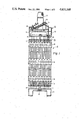
- FIG. 1 is a partially sectioned elevational view, with parts being broken away for clarity, of a fuel assembly formed in accordance with the principles of the present invention.
- FIG. 2 is a sectioned, exploded view of the components of the improved attaching structure of the present invention before assembly thereof, with a fragmentary portion of the adapter plate of the top nozzle being shown and with the sleeve of the improved attaching structure being seen bulge fitted on the upper end of the control rod guide thimble.
- FIG. 3 is the improved attaching structure seen in FIG. 2, but in its assembled position.
- FIG. 4 is a top plan view, as seen by line 4--4 of FIG. 3, looking down on the assembled structure showing the top flange on the locking tube being deformed at two locations into indentations provided in the adapter plate.
- FIG. 5 is a section taken along line 5--5 of FIG. 3 showing the three elongated slots provided in the sleeve.
- FIG. 6 is similar to FIG. 3, but shows an alternative embodiment of the means for securing the locking tube in its inserted position.
- the securing means being represented in this view by a split retainer ring.
- FIG. 7 is another alternative embodiment of the locking tube securing means, showing external threads on the enlarged shoulder of the locking tube that threadably engage the internal threads provided in the top bore.
- FIG. 8 is yet another alternative embodiment of the locking tube securing means, showing the locking tube being bulge expanded into the bulge cavity of the sleeve.
- FIG. 9 is similar to FIG. 2, but shows still another alternative embodiment of the components making up the improved attaching structure of the present invention.
- FIG. 10 is a top plan view, as seen by line 10--10 of FIG. 9, looking down on the top of the sleeve mounted on the upper end of the control rod guide thimble.
- FIG. 11 is an enlarged view of a fragmentary portion of the upper end of a sleeve similar to the sleeve of the improved attaching structure seen in FIG. 9, but having a slightly outwardly flared upper end above the circumferential bulge.
- FIG. 12 is a section taken along line 12--12 in FIG. 9 showing the bulge fittings at four circumferential locations of the lower end of the sleeve and the upper end of the control rod guide thimble.
- FIG. 13 is an enlarged fragmentary view of the upper end of the locking member of the improved attaching structure seen in FIG. 9, showing a slightly outwardly tapered or flared upper peripheral edge portion thereof.
- FIG. 14 is a sectional view of the improved attaching structure of FIG. 9, showing the components in assembled position.
- FIG. 15 is a top plan view, as seen by line 15--15 of FIG. 14, showing a pair of bulge fittings in the locking tube of the improved attaching structure of FIG. 14.
- FIG. 16 is a sectional view of an alternative embodiment wherein the guide thimble and extension sleeve are made of one piece construction.
- FIG. 1 there is shown a partially sectioned elevational view, with parts broken away for clarity, of a fuel assembly constructed in accordance with well known practices, being indicated generally by the numeral 10, which incorporates a preferred embodiment of the invention.
- the fuel assembly 10 basically comprises a lower end structure or bottom nozzle 12 for supporting the assembly on the lower core plate (not shown) in the core region of a reactor (not shown); a number of longitudinally extending control rod guide tubes or thimbles 14 projecting upwardly from the bottom nozzle 12; a plurality of transverse grids 16 axially spaced along the guide thimbles 14; an organized array of elongated fuel rods 18 transversely spaced and supported by the grids 16; an instrumentation tube 20 located in the center of the assembly; and an upper end structure or top nozzle, generally designated by the numeral 22, attached to the upper ends of the guide thimbles 14, in a manner fully described below, to form an integral assembly capable of being conventionally handled without damaging the assembly components.
- the top nozzle 22 includes a transversely extending adapter plate 24 having upstanding sidewalls 26 secured to the peripheral edges thereof in defining an enclosure or housing.
- An annular flange 28 is secured to the top of sidewalls 26.
- leaf springs 30 Suitably clamped to the annular flange 28 are leaf springs 30 (only one of which being shown in FIG. 1) which cooperate with the upper core plate (not shown) in a conventional manner to prevent hydraulic lifting of the fuel assembly caused by upward coolant flow while allowing for changes in fuel assembly length due to core induced thermal expansion and the like.
- a conventional rod cluster control assembly 32 Disposed within the opening defined by the annular flange 28 is a conventional rod cluster control assembly 32 having radially extending flukes 34 being connected to the upper ends of the control rods 36 for vertically moving the control rods in the control rod guide thimbles 14 in a well known manner.
- the fuel assembly 10 depicted in the drawings is of the type having a square array of fuel rods 18 with the control rod guide thimbles strategically arranged within the fuel rod array. Further, the bottom nozzle 12 and likewise the top nozzle 22 are generally square in cross section.
- the specific fuel assembly represented in the drawings is for illustrational purposes only, it is to be understood, that neither the shape of the nozzles or the number and configuration of the fuel rods and guide thimbles are to be limiting, and that the invention is equally applicable to different shapes, configurations, and arrangements than the ones specifically shown.
- the transverse grids 16 are attached to the longitudinally extending guide thimbles 14 at predetermined axially spaced locations; the fuel rods 18 are inserted through the grids 16; the lower nozzle 12 is suitably attached to the lower ends of the guide thimbles 14; and then the top nozzle 22 is attached to the upper ends of the guide thimbles 14 in the manner fully described below in accordance with the improved attaching structure of the present invention, being generally designated by the numeral 38.
- each of the guide thimbles 14 is attached to the top nozzle 22, the description that follows is directed to the attachment arrangement for only one of the guide thimbles, the other guide thimbles being attached in the same manner.
- the improved attaching structure 38 basically comprises an inner socket, generally indicated by the numeral 40, defined on the upper end of the guide thimble 14; a outer socket, generally indicated by the numeral 42, defined in the top nozzle 22; and a locking member, generally indicated by the numeral 44, for retaining the inner socket 40 in locking engagement with the outer socket 42 to thereby removably attach the top nozzle 22 on the guide thimbles 14.
- the inner socket 40 is preferably in the form of an elongated sleeve 46 having its lower end bulge fitted, in a well known manner, on the upper end of the guide thimble 14.
- a circumferential bulge 48 is formed on the upper end portion of the sleeve 46 and at least one, and preferably three, (see FIG. 5), elongated slots 50 are provided in the sleeve's upper end portion.
- the shape of the bulge 48 is in the form of an arc, the purpose of which will become readily apparent later on in the specification.
- the three elongated slots 50 are equally spaced about the wall of the sleeve and extend axially from the top edge of the sleeve downwardly through and a short distance beyond the bulge 48.
- the purpose of the slots 50 is to permit inward elastic collapse of the upper end portion of the sleeve 46 (a compressed releasing position) for inserting and removing the inner socket 40 into and from the outer socket 42.
- sleeve 46 may be the sleeve which is commonly attached to the upper grid 16, which in turn is bulge fitted on the upper end of the guide thimble, or, on the otherhand, it may be a sleeve separate from the grid sleeve.
- the above described inner socket may be the upper end of the guide thimble itself (without the use of a sleeve) with the circumferential bulge formed on and the elongated slots being provided in the upper end portion of the thimble.
- the outer socket 42 is preferably in the form of an axial extending passageway defined in the adapter plate 24 of the top nozzle 22 and is composed of a top bore 52, a middle bore 54, and a lower bore 56, with the lower bore having an annular groove 58 which divides the lower bore 54 into an upper segment 56a (above the groove 58) and a lower segment 56a (below the groove 58).
- the annular groove 58 is in a form or shape conforming to the arcuate shape of the bulge 48 on sleeve 46.
- the top bore 52, middle bore 54, and lower bore 56 are all coaxial.
- the top bore 52 has a diameter greater than the diameter of the middle bore 54 and the diameter of the middle bore 54 is smaller than the diameter of the lower bore 56.
- the diameter of the middle bore 54 is equal to the inner diameter of the sleeve 46
- the diameter of the lower bore 56 is equal to the outer diameter of the sleeve 46
- the diameter of annular groove 58 is equal to the outer diameter of the bulge 48 in its expanded locking position.
- the intersection of the middle bore 54 with the upper bore 52 defines an upper ledge 60 whereas the intersection of the middle bore 54 with the lower bore 56 defines a lower ledge 62, with the width of ledge 62 being approximately equal to the radial thickness of the wall of sleeve 46.
- the arrangement, size and shape of the bores and annular recess of the outer socket 42 and the size and shape of the upper end portion of sleeve 46 and its bulge 48 (the inner socket 40) is such that when the inner socket 40 is in its expanded locking position within the outer socket 42 (as seen in FIG. 3), the bulge 48 is in mating engagement with the annular groove 58, the top end or edge of sleeve 46 abuts the lower ledge 62, the section of the sleeve above the bulge 48 is in snug contact with the upper segment 56a of lower bore 56, and the section of the sleeve 46 below the bulge 48 is in snug contact with the lower segment 56b of the lower bore 56.
- the relationship is such as to produce a rigid or tight clearance fit between the inner socket 40 and outer socket 42.
- the primary purpose of the lower ledge 62 is to serve as a stop or an alignment guide for proper axial positioning of the sleeve 46 in the passageway when the inner socket 40 is inserted into the outer socket 42.
- the attaching structure 38 also includes locking member 44 for retaining the inner socket 40 in its expanded locking position in the outer socket 42.
- locking member 44 is in the form of an elongated tube having a circular body portion 64 and an enlarged radially extending shoulder 66 formed on the upper end of the tube.
- the outer diameter of the body portion 64 is slightly less than the diameter of the middle bore 54, and likewise the inner diameter of sleeve 46, for snug slidable engagement therethrough in establishing a friction fit therebetween.
- the outer diameter of the enlarged shoulder 66 is slightly less than the diameter of the top bore 52.
- the shoulder 66 is disposed in the top bore 52 of the adapter plate 24 and rests on the upper ledge 60 while the tubular body portion 64 extends through the middle bore 54 and into the upper end portion of sleeve 46.
- the arrangement is such that the locking member 44, in its inserted position, retains the bulge 48 in its expanded locking engagement with the annular groove 58 and prevents it from moving to its compressed releasing position, thus maintaining the inner socket 40 in locking engagement with the outer socket 42, and thereby the attachment of top nozzle 22 on the upper ends of guide thimbles 14.
- the improved attaching structue 38 further includes means for securing the locking member 44 in its inserted position in the inner socket 40.
- the securing means takes on the form of an upstanding, thin wall, circular flange 68 formed on the upper edge of shoulder 66 of locking member 44 which is deformable into indentations or cavities 70 provided in the adapter plate 24, adjacent the top bore 52 (see FIGS. 3 and 4).
- the attachment and detachment of the top nozzle 22 on the guide thimbles 14 is as follows: The upper end portion of sleeve 46 is moved to its compressed releasing position (inward elastic collapse of bulge 48) and inserted into the lower bore 56 whereupon the end portion moves to its expanded locking position with the bulge 48 being seated in the annular groove 58. The locking member 44 is then inserted into the inner socket 40 to maintain the bulge 48 in locking engagement with the groove 58. And then the flange 68 is deformed into the indentations 70.
- the inner socket 40, outer socket 42 and locking member 44 are assembled together as described above as a subassembly and then the lower end of the sleeve 46 is bulge expanded on the upper end of the guide thimble 14.
- the locking member 44 is rotated to override the securing engagement of the flange 68 in the indentations 70 and then the locking member 44 is removed from its inserted position.
- the adapter plate 24 is lifted up which forces inward elastic collapse of the upper end portion of sleeve 46 to its compressed released position to thereby allow the bulge 48 to pass through the lower segment 56b of lower bore 56.
- FIGS. 6, 7 and 8 each show an alternative embodiment of the improved attaching structure 38 of the present invention.
- Each of these alternative embodiments are substantially identical to the preferred embodiment seen in FIGS. 2 and 3, except for the form of the securing means to retain the locking member 44 in its inserted position within the inner socket 40.
- the securing means is in the form of a split snap ring 72 disposed within an annular recess 74 in the top bore 52 of adapter plate 24. The ring 72 engages the top surface of shoulder 66 to prevent the locking member 44 from moving vertically upwardly out of its inserted position.
- the securing means is represented in the form of external threads 76 on the outer lateral surface of shoulder 66 which threadably engage internal threads 78 provided on the wall of the top bore 52.
- the securing means takes on the form of the body portion 64 of the locking member 44 being bulge fitted or expanded, at the location indicated by numeral 80, into the cavity formed by the bulge 48 of sleeve 46.
- FIGS. 9 to 15 show still another alternative embodiment of the improved attaching structure of the present invention. Unlike each of the alternative embodiments of FIGS. 6, 7 and 8 which differed only from the preferred embodiment of FIGS. 2 and 3 in the form of the securing means of the locking member, the alternative embodiment of FIGS.
- the sleeve or inner socket generally indicated by the numeral 82, defined on the upper end of the guide thimble 14
- the outer socket generally indicated by the numeral 84, defined in the top nozzle 22
- the locking member generally indicated by the numeral 86, for retaining the inner socket 82 in locking engagement with the outer socket 84 to thereby removably attach the top nozzle 22 on the guide thimbles 14.
- the inner socket 82 has a circumferential bulge 88 formed on its upper end portion only a short distance below its upper edge 90. Also, there are preferably four (instead of three) elongated slots 92 (see FIG. 10) provided in the upper end portion of the inner socket 82. Further, the inner socket 82 has its lower end portion bulge fitted at three axially spaced regions to the guide thimble with four bulges 94 circumferentially displaced approximately ninety degrees from one another at each of the three regions. However, with respect to the latter, it is clear from the modified form of the inner socket 96, shown in FIG. 16, the inner socket and upper end portion of the guide thimble 14 could be a single integral structure. This also applies to the inner socket 40 in FIGS.
- FIG. 11 illustrates a slightly modified configuration for the inner socket 82 from that seen in FIGS. 9 and 14 in that the upper end 98 is slightly outwardly flared (for instance 4-5 degrees) above the circumferential bulge 88.
- the outer socket 84 preferably in the form of an axial extending passageway defined in the adapter plate 24 of the top nozzle 22 is composed of an upper bore 98 and a lower bore 100.
- the lower bore 100 is of considerable greater axial length than the upper bore 98 and has an annular groove 102 which is spaced a short distance below a ledge 104 formed at the intersection of the upper and lower bores 98,100.
- the lower bore 100 has a diameter which is greater than that of the upper bore 98; therefore, the ledge 104 faces in a downward direction.
- the primary purpose of the ledge 104 is to serve as a stop or an alignment guide for proper axial positioning of the sleeve or inner socket 82 in the passageway when the inner socket is inserted into the outer socket 84. As seen in FIG. 14, the upper edge 90 abuts the ledge 104.
- the securing means of the locking member 86 takes the form of a pair of bulges 106 (see FIG. 15) formed into the upper portion of the locking member 86 after insertion into the passageway.
- the bulges 106 fit into the circumferential groove 88 in the adapter plate passageway or outer socket 84.
- the securing means further includes a slightly outwardly flared (for instance 1-2 degrees) upper peripheral edge portion 108 of the locking member 86.
- the outer diameter of the upper edge portion 108 of the locking member 86 is slightly larger than the diameter of the upper bore 98.
Landscapes
- Physics & Mathematics (AREA)
- Engineering & Computer Science (AREA)
- Plasma & Fusion (AREA)
- General Engineering & Computer Science (AREA)
- High Energy & Nuclear Physics (AREA)
- Fuel-Injection Apparatus (AREA)
Abstract
Description
Claims (23)
Priority Applications (1)
| Application Number | Priority Date | Filing Date | Title |
|---|---|---|---|
| US06/644,758 US4631168A (en) | 1983-09-30 | 1984-08-27 | Nuclear reactor fuel assembly with a removable top nozzle |
Applications Claiming Priority (2)
| Application Number | Priority Date | Filing Date | Title |
|---|---|---|---|
| US53777583A | 1983-09-30 | 1983-09-30 | |
| US06/644,758 US4631168A (en) | 1983-09-30 | 1984-08-27 | Nuclear reactor fuel assembly with a removable top nozzle |
Related Parent Applications (1)
| Application Number | Title | Priority Date | Filing Date |
|---|---|---|---|
| US53777583A Continuation-In-Part | 1983-09-30 | 1983-09-30 |
Publications (1)
| Publication Number | Publication Date |
|---|---|
| US4631168A true US4631168A (en) | 1986-12-23 |
Family
ID=27065611
Family Applications (1)
| Application Number | Title | Priority Date | Filing Date |
|---|---|---|---|
| US06/644,758 Expired - Lifetime US4631168A (en) | 1983-09-30 | 1984-08-27 | Nuclear reactor fuel assembly with a removable top nozzle |
Country Status (1)
| Country | Link |
|---|---|
| US (1) | US4631168A (en) |
Cited By (21)
| Publication number | Priority date | Publication date | Assignee | Title |
|---|---|---|---|---|
| US4738821A (en) * | 1987-03-23 | 1988-04-19 | Westinghouse Electric Corp. | Reconstitutable nuclear fuel assembly having locking tubes with dimples |
| US4820475A (en) * | 1985-09-12 | 1989-04-11 | Westinghouse Electric Corp. | Burnable absorber rod push out attachment joint |
| US4999154A (en) * | 1988-09-19 | 1991-03-12 | Framatome | Demountable fuel assembly for a nuclear reactor cooled by light water |
| US5015435A (en) * | 1988-09-19 | 1991-05-14 | Framatome | Device for demountable fastening of a guide tube into an end fitting of a fuel assembly of a nuclear reactor |
| US5037603A (en) * | 1990-08-03 | 1991-08-06 | Westinghouse Electric Corp. | Hand held tool for removing and replacing a top nozzle locking tube |
| US5084230A (en) * | 1990-12-12 | 1992-01-28 | Westinghouse Electric Corp. | Hand held tool for removing and replacing a removable top nozzle |
| US5091142A (en) * | 1988-09-19 | 1992-02-25 | Framatome | Method for extracting a locking sleeve from a demountable guide tube of a nuclear reactor fuel assembly |
| US5282232A (en) * | 1988-02-15 | 1994-01-25 | Framatome | Nuclear reactor upper internal equipment with cluster guide devices |
| US5363423A (en) * | 1993-08-19 | 1994-11-08 | Westinghouse Electric Corporation | Quick release top nozzle assembly |
| WO1995014996A1 (en) * | 1993-11-25 | 1995-06-01 | Abb Atom Ab | Fuel assembly with guide thimbles including locking elements for a nuclear reactor |
| US5844958A (en) * | 1993-12-30 | 1998-12-01 | Framatome | Dismountable fuel assembly of a nuclear reactor cooled by light water |
| US6115440A (en) * | 1998-04-29 | 2000-09-05 | Westinghouse Electric Company Llc | Quick release, removable top nozzle assembly |
| US20110048846A1 (en) * | 2006-07-13 | 2011-03-03 | Compagnie Plastic Omnium | Noise attenuator for a hydraulic fluid pipe, item comprising this attenuator, pipe comprising this item and method of assembly |
| WO2011149408A1 (en) | 2010-05-25 | 2011-12-01 | Westinghouse Electric Sweden Ab | A fuel assembly, a guide thimble device and use of the guide thimble device |
| US20150302941A1 (en) * | 2012-10-22 | 2015-10-22 | Open Joint-Stock Company "Tvel" | Nuclear reactor fuel assembly |
| CN106531231A (en) * | 2016-11-30 | 2017-03-22 | 中广核研究院有限公司 | Fuel assembly and clamping device thereof |
| US9978467B2 (en) * | 2014-11-13 | 2018-05-22 | Framatome Inc. | Excavation and weld repair methodology for pressurized water reactor piping and vessel nozzles |
| CN109935360A (en) * | 2017-12-19 | 2019-06-25 | 中国原子能科学研究院 | A kind of fuel assembly guide pipe and upper tube socket connection structure and fuel assembly skeleton |
| US11355251B2 (en) * | 2017-11-09 | 2022-06-07 | Kepco Nuclear Fuel Co., Ltd. | System for separating and coupling top nozzle of nuclear fuel assembly |
| EP3753029B1 (en) | 2018-02-12 | 2022-06-08 | Westinghouse Electric Company Llc | Thermal sleeve |
| CN119170306A (en) * | 2024-09-11 | 2024-12-20 | 四川大学 | Stepped connection device and nuclear energy system fuel assembly |
Citations (10)
| Publication number | Priority date | Publication date | Assignee | Title |
|---|---|---|---|---|
| GB1288610A (en) * | 1969-01-10 | 1972-09-13 | ||
| US3770583A (en) * | 1971-05-20 | 1973-11-06 | Combustion Eng | Fuel assembly hold-down device |
| US3814667A (en) * | 1971-05-20 | 1974-06-04 | Combustion Eng | Fuel assembly hold-down device |
| US3828868A (en) * | 1969-11-26 | 1974-08-13 | Babcock & Wilcox Co | Fuel assembly for a nuclear reactor |
| US3992259A (en) * | 1973-06-25 | 1976-11-16 | Combustion Engineering, Inc. | Fuel assembly for a nuclear reactor |
| US4326921A (en) * | 1980-05-16 | 1982-04-27 | Westinghouse Electric Corp. | Control rod guide thimble for nuclear reactor fuel assemblies |
| FR2493024A1 (en) * | 1980-10-29 | 1982-04-30 | Franco Belge Combustibles | Connector for fuel rod assemblies in nuclear reactor - where clamping ring is used to locate ends of control rod guide tubes in holes in plate |
| FR2529704A1 (en) * | 1982-07-01 | 1984-01-06 | Commissariat Energie Atomique | DEVICE FOR THE REMOVABLE FASTENING OF A GUIDE TUBE IN THE END PIECE OF A COMBUSTIBLE NUCLEAR REACTOR ASSEMBLY |
| DE3228380A1 (en) * | 1982-07-29 | 1984-02-09 | Kraftwerk Union AG, 4330 Mülheim | Nuclear reactor fuel element |
| US4535523A (en) * | 1981-03-11 | 1985-08-20 | Commissariat A L'energie Atomique | Fuel assemblies for nuclear reactors |
-
1984
- 1984-08-27 US US06/644,758 patent/US4631168A/en not_active Expired - Lifetime
Patent Citations (10)
| Publication number | Priority date | Publication date | Assignee | Title |
|---|---|---|---|---|
| GB1288610A (en) * | 1969-01-10 | 1972-09-13 | ||
| US3828868A (en) * | 1969-11-26 | 1974-08-13 | Babcock & Wilcox Co | Fuel assembly for a nuclear reactor |
| US3770583A (en) * | 1971-05-20 | 1973-11-06 | Combustion Eng | Fuel assembly hold-down device |
| US3814667A (en) * | 1971-05-20 | 1974-06-04 | Combustion Eng | Fuel assembly hold-down device |
| US3992259A (en) * | 1973-06-25 | 1976-11-16 | Combustion Engineering, Inc. | Fuel assembly for a nuclear reactor |
| US4326921A (en) * | 1980-05-16 | 1982-04-27 | Westinghouse Electric Corp. | Control rod guide thimble for nuclear reactor fuel assemblies |
| FR2493024A1 (en) * | 1980-10-29 | 1982-04-30 | Franco Belge Combustibles | Connector for fuel rod assemblies in nuclear reactor - where clamping ring is used to locate ends of control rod guide tubes in holes in plate |
| US4535523A (en) * | 1981-03-11 | 1985-08-20 | Commissariat A L'energie Atomique | Fuel assemblies for nuclear reactors |
| FR2529704A1 (en) * | 1982-07-01 | 1984-01-06 | Commissariat Energie Atomique | DEVICE FOR THE REMOVABLE FASTENING OF A GUIDE TUBE IN THE END PIECE OF A COMBUSTIBLE NUCLEAR REACTOR ASSEMBLY |
| DE3228380A1 (en) * | 1982-07-29 | 1984-02-09 | Kraftwerk Union AG, 4330 Mülheim | Nuclear reactor fuel element |
Cited By (27)
| Publication number | Priority date | Publication date | Assignee | Title |
|---|---|---|---|---|
| US4820475A (en) * | 1985-09-12 | 1989-04-11 | Westinghouse Electric Corp. | Burnable absorber rod push out attachment joint |
| US4738821A (en) * | 1987-03-23 | 1988-04-19 | Westinghouse Electric Corp. | Reconstitutable nuclear fuel assembly having locking tubes with dimples |
| EP0289732A3 (en) * | 1987-03-23 | 1989-08-23 | Westinghouse Electric Corporation | Reconstitutable nuclear fuel assembly |
| US5282232A (en) * | 1988-02-15 | 1994-01-25 | Framatome | Nuclear reactor upper internal equipment with cluster guide devices |
| US4999154A (en) * | 1988-09-19 | 1991-03-12 | Framatome | Demountable fuel assembly for a nuclear reactor cooled by light water |
| US5015435A (en) * | 1988-09-19 | 1991-05-14 | Framatome | Device for demountable fastening of a guide tube into an end fitting of a fuel assembly of a nuclear reactor |
| US5091142A (en) * | 1988-09-19 | 1992-02-25 | Framatome | Method for extracting a locking sleeve from a demountable guide tube of a nuclear reactor fuel assembly |
| US5037603A (en) * | 1990-08-03 | 1991-08-06 | Westinghouse Electric Corp. | Hand held tool for removing and replacing a top nozzle locking tube |
| US5084230A (en) * | 1990-12-12 | 1992-01-28 | Westinghouse Electric Corp. | Hand held tool for removing and replacing a removable top nozzle |
| US5363423A (en) * | 1993-08-19 | 1994-11-08 | Westinghouse Electric Corporation | Quick release top nozzle assembly |
| WO1995014996A1 (en) * | 1993-11-25 | 1995-06-01 | Abb Atom Ab | Fuel assembly with guide thimbles including locking elements for a nuclear reactor |
| US6002736A (en) * | 1993-12-30 | 1999-12-14 | Framatome | Dismountable fuel assembly of a nuclear reactor cooled by light water |
| US5844958A (en) * | 1993-12-30 | 1998-12-01 | Framatome | Dismountable fuel assembly of a nuclear reactor cooled by light water |
| US6115440A (en) * | 1998-04-29 | 2000-09-05 | Westinghouse Electric Company Llc | Quick release, removable top nozzle assembly |
| US20110048846A1 (en) * | 2006-07-13 | 2011-03-03 | Compagnie Plastic Omnium | Noise attenuator for a hydraulic fluid pipe, item comprising this attenuator, pipe comprising this item and method of assembly |
| WO2011149408A1 (en) | 2010-05-25 | 2011-12-01 | Westinghouse Electric Sweden Ab | A fuel assembly, a guide thimble device and use of the guide thimble device |
| US9031185B2 (en) | 2010-05-25 | 2015-05-12 | Westinghouse Electric Sweden Ab | Fuel assembly, a guide thimble device and use of the guide thimble device |
| US9767928B2 (en) * | 2012-10-22 | 2017-09-19 | Open Joint-Stock Company “Tvel” | Nuclear reactor fuel assembly |
| US20150302941A1 (en) * | 2012-10-22 | 2015-10-22 | Open Joint-Stock Company "Tvel" | Nuclear reactor fuel assembly |
| US9978467B2 (en) * | 2014-11-13 | 2018-05-22 | Framatome Inc. | Excavation and weld repair methodology for pressurized water reactor piping and vessel nozzles |
| CN106531231B (en) * | 2016-11-30 | 2018-05-22 | 中广核研究院有限公司 | Fuel assembly and its clamping device |
| CN106531231A (en) * | 2016-11-30 | 2017-03-22 | 中广核研究院有限公司 | Fuel assembly and clamping device thereof |
| US11355251B2 (en) * | 2017-11-09 | 2022-06-07 | Kepco Nuclear Fuel Co., Ltd. | System for separating and coupling top nozzle of nuclear fuel assembly |
| CN109935360A (en) * | 2017-12-19 | 2019-06-25 | 中国原子能科学研究院 | A kind of fuel assembly guide pipe and upper tube socket connection structure and fuel assembly skeleton |
| EP3753029B1 (en) | 2018-02-12 | 2022-06-08 | Westinghouse Electric Company Llc | Thermal sleeve |
| EP3933854B1 (en) | 2018-02-12 | 2022-08-10 | Westinghouse Electric Company Llc | Replacement thermal sleeve |
| CN119170306A (en) * | 2024-09-11 | 2024-12-20 | 四川大学 | Stepped connection device and nuclear energy system fuel assembly |
Similar Documents
| Publication | Publication Date | Title |
|---|---|---|
| US4631168A (en) | Nuclear reactor fuel assembly with a removable top nozzle | |
| EP0140588B1 (en) | Nuclear reactor fuel assembly with a removable top nozzle | |
| US4617171A (en) | Device for fixing a guide tube in a recess on the end fitting of a nuclear reactor fuel assembly | |
| US4323428A (en) | Reconstitutable fuel assembly for a nuclear reactor | |
| US4603027A (en) | Removable top nozzle and tool for a nuclear reactor fuel assembly | |
| US4639998A (en) | Locking tube removal and replacement tool and method in a reconstitutable fuel assembly | |
| EP0138606B1 (en) | Nuclear reactor fuel assembly with improved top nozzle and hold-down means | |
| US5207980A (en) | Top nozzle-mounted replacement guide pin assemblies | |
| US4572816A (en) | Reconstituting a nuclear reactor fuel assembly | |
| US4699758A (en) | Reusable locking tube in a reconstitutable fuel assembly | |
| US4684498A (en) | Guide thimble captured locking tube in a reconstitutable fuel assembly | |
| US4664874A (en) | Reusable locking tube insertion and removal fixture and method in a reconstitutable fuel assembly | |
| US20070165767A1 (en) | Terminal end-piece for a fuel assembly having a nose for orienting the flow of coolant fluid and corresponding assembly | |
| US4684503A (en) | Reconstitutable nuclear reactor fuel assembly with unitary removable top nozzle subassembly | |
| US4699759A (en) | Double lock joint for attaching top nozzle to guide thimbles of nuclear fuel assembly | |
| US4684500A (en) | Guide thimble captured locking tube in a reconstitutable fuel assembly | |
| US4638556A (en) | Locking tube insertion fixture and method in a reconstitutable fuel assembly | |
| US4638543A (en) | Locking tube removal fixture and method in a reconstitutable fuel assembly | |
| US5015435A (en) | Device for demountable fastening of a guide tube into an end fitting of a fuel assembly of a nuclear reactor | |
| US4699760A (en) | Fuel assembly skeleton with structural and non-structural top nozzle/guide thimble joints | |
| US5363423A (en) | Quick release top nozzle assembly | |
| JPH0795112B2 (en) | Integrated locking device for upper nozzle | |
| JPH083552B2 (en) | Fuel assembly upper nozzle | |
| US4688416A (en) | Fixture and method for rectifying damaged guide thimble insert sleeves in a reconstitutable fuel assembly | |
| US5479464A (en) | Expandable top nozzle and device for securing same to a nuclear fuel assembly |
Legal Events
| Date | Code | Title | Description |
|---|---|---|---|
| AS | Assignment |
Owner name: WESTINGHOUSE ELECTRIC CORPORATION, WESTINGHOUSE BU Free format text: ASSIGNMENT OF ASSIGNORS INTEREST.;ASSIGNORS:SHALLENBERGER, JOHN M.;FERLAN, STEPHEN J.;REEL/FRAME:004310/0874 Effective date: 19840817 |
|
| STCF | Information on status: patent grant |
Free format text: PATENTED CASE |
|
| FEPP | Fee payment procedure |
Free format text: PAYOR NUMBER ASSIGNED (ORIGINAL EVENT CODE: ASPN); ENTITY STATUS OF PATENT OWNER: LARGE ENTITY |
|
| FPAY | Fee payment |
Year of fee payment: 4 |
|
| AS | Assignment |
Owner name: HUGHES MISSILE SYSTEMS COMPANY, CALIFORNIA Free format text: ASSIGNMENT OF ASSIGNORS INTEREST.;ASSIGNOR:GENERAL DYNAMICS CORPORATION;REEL/FRAME:006276/0973 Effective date: 19920820 |
|
| FPAY | Fee payment |
Year of fee payment: 8 |
|
| FPAY | Fee payment |
Year of fee payment: 12 |
|
| AS | Assignment |
Owner name: WESTINGHOUSE ELECTRIC CO. LLC, PENNSYLVANIA Free format text: ASSIGNMENT OF ASSIGNORS INTEREST;ASSIGNOR:CBS CORPORATION (FORMERLY KNOWN AS WESTINGHOUSE ELECTRIC CORPORATION;REEL/FRAME:010070/0819 Effective date: 19990322 |