US4626160A - Unmanned transfer system for transferring works to machining tools - Google Patents
Unmanned transfer system for transferring works to machining tools Download PDFInfo
- Publication number
- US4626160A US4626160A US06/725,367 US72536785A US4626160A US 4626160 A US4626160 A US 4626160A US 72536785 A US72536785 A US 72536785A US 4626160 A US4626160 A US 4626160A
- Authority
- US
- United States
- Prior art keywords
- machining tools
- pallet
- works
- traverse carriage
- carriage
- Prior art date
- Legal status (The legal status is an assumption and is not a legal conclusion. Google has not performed a legal analysis and makes no representation as to the accuracy of the status listed.)
- Expired - Fee Related
Links
- 238000003754 machining Methods 0.000 title abstract description 32
- 230000007246 mechanism Effects 0.000 description 6
- 238000010276 construction Methods 0.000 description 5
- 230000033001 locomotion Effects 0.000 description 5
- 241000282472 Canis lupus familiaris Species 0.000 description 4
- 238000000034 method Methods 0.000 description 4
- 101150072399 LSC1 gene Proteins 0.000 description 3
- 101100511858 Saccharomyces cerevisiae (strain ATCC 204508 / S288c) LSB1 gene Proteins 0.000 description 3
- 230000009471 action Effects 0.000 description 3
- 230000008569 process Effects 0.000 description 3
- 101001050886 Homo sapiens Lysine-specific histone demethylase 1A Proteins 0.000 description 2
- 102100024985 Lysine-specific histone demethylase 1A Human genes 0.000 description 2
- 230000004044 response Effects 0.000 description 2
- 101000619676 Drosophila melanogaster Lipid storage droplets surface-binding protein 2 Proteins 0.000 description 1
- 101000613960 Homo sapiens Lysine-specific histone demethylase 1B Proteins 0.000 description 1
- 102100040596 Lysine-specific histone demethylase 1B Human genes 0.000 description 1
- 244000145845 chattering Species 0.000 description 1
- 238000004886 process control Methods 0.000 description 1
Images


Classifications
-
- B—PERFORMING OPERATIONS; TRANSPORTING
- B65—CONVEYING; PACKING; STORING; HANDLING THIN OR FILAMENTARY MATERIAL
- B65G—TRANSPORT OR STORAGE DEVICES, e.g. CONVEYORS FOR LOADING OR TIPPING, SHOP CONVEYOR SYSTEMS OR PNEUMATIC TUBE CONVEYORS
- B65G37/00—Combinations of mechanical conveyors of the same kind, or of different kinds, of interest apart from their application in particular machines or use in particular manufacturing processes
- B65G37/02—Flow-sheets for conveyor combinations in warehouses, magazines or workshops
-
- B—PERFORMING OPERATIONS; TRANSPORTING
- B23—MACHINE TOOLS; METAL-WORKING NOT OTHERWISE PROVIDED FOR
- B23Q—DETAILS, COMPONENTS, OR ACCESSORIES FOR MACHINE TOOLS, e.g. ARRANGEMENTS FOR COPYING OR CONTROLLING; MACHINE TOOLS IN GENERAL CHARACTERISED BY THE CONSTRUCTION OF PARTICULAR DETAILS OR COMPONENTS; COMBINATIONS OR ASSOCIATIONS OF METAL-WORKING MACHINES, NOT DIRECTED TO A PARTICULAR RESULT
- B23Q7/00—Arrangements for handling work specially combined with or arranged in, or specially adapted for use in connection with, machine tools, e.g. for conveying, loading, positioning, discharging, sorting
- B23Q7/14—Arrangements for handling work specially combined with or arranged in, or specially adapted for use in connection with, machine tools, e.g. for conveying, loading, positioning, discharging, sorting co-ordinated in production lines
- B23Q7/1426—Arrangements for handling work specially combined with or arranged in, or specially adapted for use in connection with, machine tools, e.g. for conveying, loading, positioning, discharging, sorting co-ordinated in production lines with work holders not rigidly fixed to the transport devices
-
- B—PERFORMING OPERATIONS; TRANSPORTING
- B65—CONVEYING; PACKING; STORING; HANDLING THIN OR FILAMENTARY MATERIAL
- B65G—TRANSPORT OR STORAGE DEVICES, e.g. CONVEYORS FOR LOADING OR TIPPING, SHOP CONVEYOR SYSTEMS OR PNEUMATIC TUBE CONVEYORS
- B65G1/00—Storing articles, individually or in orderly arrangement, in warehouses or magazines
- B65G1/02—Storage devices
- B65G1/04—Storage devices mechanical
- B65G1/0407—Storage devices mechanical using stacker cranes
Definitions
- the present invention relates to an unmanned transfer system and, more particularly, to an unmanned transfer system for transferring necessary materials such as works or tools between the racks of an automatic warehouse and machining tools.
- an unmanned transfer system for transferring works to machining tools which system comprises: a plurality of machining tools arranged along racks stored with works to be supplied to said machining tools; a stacker crane adapted to run between said racks and said machining tools; and a plurality of auto-pallet changers interposed between said stacker crane and said machining tools for automatically tranferring said works between said stacker crane and said machining tools.
- the system according to the present invention uses both centering pushers for centering the pallet with respect to the transverse carriages on the lift and a centering cam for positioning the traverse carriages with respect to the target auto-pallet changer so that positioning is influenced by neither the precision with which the stacker crane is stopped nor the chatterings of the lift and the guide roller. Moreover, even if the pallet transferred from the warehouse to the slide fork of the crane is placed offset the center of the slide fork, the system of the present invention can precisely position the pallet on the auto-pallet changer with a positioning precision sufficiently ranging within ⁇ 0.5 mm. Furthermore, since the crane is equipped with the positioning mechanism, a number of the auto-pallet changers can be handled by means of a single positioning mechanism in an economical manner.
- the works can be directly transferred from the stacker crane to the machining tools through the auto-pallet changers in an automatic manner.
- the transfer time can be shortened, and any carts for warehousing and delivering purposes can be dispensed with to simplify process control so that the system can be unmanned to reduce mistakes in management and so that the cost for the whole system can be reduced.
- FIG. 1 is a perspective view showing the overall construction arrangement of an unmanned transfer system according to one embodiment of the present invention
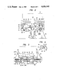
- FIGS. 2 and 3 are side and front elevations showing a positioning mechanism of a crane to be used in the embodiment shown in FIG. 1;
- FIG. 4 is a perspective view showing a centering cam to be used in the mechanism of FIGS. 2 and 3
- FIG. 5-a is a side elevation showing the construction of the centering cam
- FIGS. 5-b to 5-d are sections taken along lines I--I, II--II and III--III of FIG. 5;
- FIG. 6 is a partially sectional front elevation showing the construction of the centering cam.
- FIG. 7 is a time chart of respective switches for processes of positioning a pallet on the crane with respect to auto-pallet changers.
- reference numeral 1 indicates racks of an automatic warehouse or the like for storing necessary materials such as works or tools.
- racks In front of the racks 1, there runs a stacker crane 3 which is guided by rails 2.
- a plurality of machining tools 4 such as machining centers are arranged in front of and along the racks 1.
- a plurality of auto-pallet changers 5 Between the machining tools 4 and rails 2 thus arranged, there are arranged a plurality of auto-pallet changers 5 (which will hereinafter be referred to as "APCs")
- the works or the like are usually set in predetermined positions on a pallet and are stored in the racks 1.
- the APCs 5 are used to transfer a pallet loaded with a work from the stacker crane 3 to the machining tools 4.
- An APC 5 may be provided for each respective machining tool, but one or two (or more) APCs may be arranged for a plurality of machining tools so that they may be subjected to control as a group. In the case of such group control, it is necessary to interpose rails 6 between the machining tools 4 and the rails 2, so that the APCs 5 may run alongside the rail 2, and it is desired that the height of the pallet receiving beds of the APCs 5 can be automatically adjusted in accordance with the height of tables or the like at the side of the machining tools.
- Letter S indicates a setting area in which works 7 are set or precisely positioned on pallets 8.
- the pallets 8 thus set are carried by an automatic trailer 9 to a warehousing and delivering station 10.
- Numeral 11 indicates a chip remover which is arranged at the side portion of the rails 2 for removing the chips or the like of the works having been machined.
- Numeral 12 indicates a tool magazine for temporarily storing the tools to be supplied to the machining tools 4.
- the tool magazine 12 is placed on a magazine table 13 at the side of the machining tools so that it may supply the tools to tool interchanging robots 14.
- the tool magazine 12 is carried by an automatic trailer 15 to a magazine station for effecting the interchanges of the tools to the magazine 12 itself.
- the respective automatic trailers 9 and 15 are made operative to run by the guidance lines 16 which are formed on the floor.
- the procedures for transferring the works by means of the unmanned transfer system according to the present invention will be described in the following.
- the works 7 having been set on pallets 8 are carried by the automatic trailer 9 to the warehousing and delivering station 10, from which they are further carried by the stacker crane 3.
- This stacker crane 3 functions to carry the works to the racks 1 and to take the works 7 out of the racks 1 and carry them to the front of the machining tool 4 in response to the command from the machining tools 4.
- the APCs 5 are arranged in front of the machining tools so that the works are precisely stopped at predetermined positions in front of those APCs 5.
- the fork at the side of the crane carrying the pallets loaded with the works advances toward a conveyor 17 for the APCs 5 so that the pallets are received at the sides of the APCs 5 by the vertical motions of the conveyor 17.
- the relationship in height between the conveyor 17 and the fork is adjusted in advance by the vertical motions of the conveyor.
- the conveyor 17 is moved up and down so that its height is adjusted to be at the same level as that of a turntable at the side of the machining tools.
- the conveyor 17 is driven to deliver the pallets to the machining tools.
- the drives of the automatic trailers 9 and 15, the warehousing and delivering control, the tool supplying control are controlled as a whole by means of a computer.
- FIGS. 2 to 4 showing the positioning mechanism
- numeral 20 indicates a positioning guide at the side of the APCs
- numeral 21 indicates crane wheels which are attached to a frame 22 so as to run on the stacker crane (which will be hereinafter referred to as a "crane") rails 2 laid in front of the racks.
- a lift 23 acting as the crane body which can be moved up and down relative to the frame 22
- traverse carriages 25 and 26 which can be moved in the direction of arrows 24.
- a slide fork 28 which is made slidable in the direction of arrows 27.
- the slide fork 28 is equipped with two-stepped traverse means 25 and 26 for the lift 23. More specifically, the traverse carriage 25 is equipped at both its ends with guide rollers 30, which are supported on guide rails 29 fixed to the lift 23, so that it is guided and supported by the guide rails 29. On the other hand, a pinion 31, which is attached to a motor MC fixed on the lift 23, is in meshing engagement with a rack 32 which in turn is fixed to the traverse carriage 25. With guide rails 33 which are fixed to the right and left of the traverse carriage 25, there are meshed guide grooves 34 which are formed in the bottom of the traverse carriage 26.
- a rack 35 attached to the slide fork 28 is in meshing engagement with a pinion 37 which is attached to a motor MB fixed to the traverse carriage 25.
- the guide rails 29 and 33 and guide grooves 34 thus far described are all arranged in the directions of the arrows 24.
- a centering cam 40 which is made rotatable on a pin 38 fixed on the traverse carriage 25, has a semicircular shape, as viewed from the side, and its side 39 has a taper or wedge shape. That centering cam 40 is so positioned that it can be forced in the wedge shape into the gap between two positioning rollers 40', which are juxtaposed to each other at predetermined positions on the positioning guide 20, by the rotations in the direction of arrow 36.
- a gear 46 which is fixed to the aforementioned centering rod 41, is in meshing engagement with a gear 49, which is fixed to a pin 48 protruding from a gear box 47, to which a motor MA is connected.
- a limit switch LSA1 is disposed at the side of the traverse carriage 25 for determining the closed position of the centering pusher 45 when it engages with the dog DA of the centering pusher 45.
- a limit switch LSA2 mounted on the aforementioned pusher 45 detects the center position of a pallet P relative to the traverse carriage 25.
- a limit switch LSB1 is disposed at the side of the traverse carriage 25 for centering the traverse carriage 26 relative to the traverse carriage 25 when it engages with the dog DB of the traverse carriage 26.
- a limit switch LSC1 is disposed at the side of the lift 23 for centering the traverse carriage 25 relative to the lift 23 when it engages with the dog DC of the traverse carriage 25.
- FIGS. 5 and 6 the mechanism for positioning the traverse carriage 25 with respect to the APCs is shown in an enlarged scale.
- the pin 38 is rotatably supported between bearings 51 and 51 which are mounted in the lower side of the traverse carriage 25.
- Said pin 38 has its center portion fixing the semicircular centering cam 40 thereto by means of a key 52 and both its ends fastening lock nuts 53 and 53 so that the centering cam 40 is fixed in position to the pin 38.
- a gear 54 which is in meshing engagement with a gear 55 at the sided of a motor MD.
- To the other ends of the pin 38 there are fixed dogs DD1 and DD2 which are shifted 180 degrees in phase for actuating contactless switches LSD1 and LSE2 disposed at the side of the traverse carriage 25.
- the centering cam 40 is formed, as has been described hereinbefore, into a semicircular shape having a radius R about the pin 38, as viewed from the side, and its band-shaped portion 39 having a width l metered from the outer circumference is tapered in the circumferential direction.
- the thickness of the band-shaped portion 39 having the width is continuously changed, as is expressed by equalities of t 1 ⁇ t 2 ⁇ t 3 .
- the band-shaped portion 39 advances into the gap between the paired positioning rollers 40' and 40' so that the traverse carriage 25 is positioned by the wedge action in the predetermined position between the rollers 40' and 40', i.e., with respect to the APCs.
- the gap between the rollers 40' and 40' is equal to or smaller the maximum width t 3 of the band-shaped portion 39.
- the motor MA is a torque motor for opening and closing the centering pushers 45
- the motor MB is a motor with a brake for centering the traverse carriage 26 with respect to the traverse carriage 25 at an initial unloaded state
- the motor MC is a motor with a brake for centering the traverse carriage 25 with respect to the lift 23 at the initial unloaded state
- the motor MD is a motor with a brake for opening and closing the centering cam 40.
- the crane in response to the work requiring command from the machining tool, the crane is positioned to a target rack of the warehouse so that the pallet set with the designated work is transferred to the lift by the action of the slide fork.
- the pallet is placed while being offset from the center of the slide fork, and the crane loaded with the pallet is moved to a designated APC, at which the positioning operation is stopped.
- the positioning operation at this time is so coarse as to have a level of about ⁇ 5 mm.
- the brake of the motor MB is released, and the motor MA is energized to rotate the centering rod 41 through the gear box 47 and the gears 49 and 46 so that the centering pusher 45 is moved in the directions of arrows 50 and 50 by the actions of the thread 42 and 43, whereby the pallet P is precisely centered at a predetermined position with respect to the traverse carriage 25.
- the brake of the motor MB is applied to lock the traverse carriage 26 with respect to the traverse carriage 25.
- the pallet P is centered relative to the traverse carriage 25.
- the brake of the motor MC is released, and the centering cam 40 is rotated in the direction of the arrow 36 into meshing engagement with the positioning rollers 40' and 40' so that the traverse carriage 25 is precisely positioned relative to that particular APC.
- the pallet P is precisely positioned relative to the APC through the traverse carriages 25 and 26.
- the respective limit switches LSA1, LSB1, LSC1 and LSD1 are at their ON states.
- the limit switch LSA1 is turned off.
- the limit switch LSB1 is turned off.
- the pallet is centered with respect to the traverse carriage 25, and the pushers 45 are then returned to their initial positions, as indicated at 50b, by the reverse rotations of the motor MA.
- the motor MD drives the centering cam 40 into the gap between the rollers 40' and 40' , as indicated at 36a.
- the contactless switch LSD2 is turned on to stop the rotations of the motor MD so that the traverse carriage 25 is centered with respect to the APC.
- the limit switch LSC1 is turned off in accordance with the movement of the traverse carriage 25.
Landscapes
- Engineering & Computer Science (AREA)
- Mechanical Engineering (AREA)
- Warehouses Or Storage Devices (AREA)
- General Factory Administration (AREA)
- Multi-Process Working Machines And Systems (AREA)
Abstract
An unmanned transfer system for transferring necessary materials such as works or tools between the racks of an automatic warehouse and machining tools. The unmanned transfer system includes a plurality of machining tools which are arranged along the racks stored with the works to be supplied to the machining tools. Further included is a stacker crane which is adapted to run between the racks and the machining tools. A plurality of auto-pallet changers are interposed between the stacker crane and the machining tools for automatically transferring the works between the stacker crane and the machining tools.
Description
This is a continuation of application Ser. No. 380,813, filed on May 21, 1982, now abandoned.
The present invention relates to an unmanned transfer system and, more particularly, to an unmanned transfer system for transferring necessary materials such as works or tools between the racks of an automatic warehouse and machining tools.
It is an object of the present invention to provide an unmanned transfer system which has its construction and process simplified and its efficiency improved by making it possible to directly transfer necessary materials such as works or tools between a stacker crane for warehousing, delivering or other purposes and machining tools with the aid of auto-pallet changers.
According to a feature of the present invention, there is provided an unmanned transfer system for transferring works to machining tools, which system comprises: a plurality of machining tools arranged along racks stored with works to be supplied to said machining tools; a stacker crane adapted to run between said racks and said machining tools; and a plurality of auto-pallet changers interposed between said stacker crane and said machining tools for automatically tranferring said works between said stacker crane and said machining tools.
The system according to the present invention uses both centering pushers for centering the pallet with respect to the transverse carriages on the lift and a centering cam for positioning the traverse carriages with respect to the target auto-pallet changer so that positioning is influenced by neither the precision with which the stacker crane is stopped nor the chatterings of the lift and the guide roller. Moreover, even if the pallet transferred from the warehouse to the slide fork of the crane is placed offset the center of the slide fork, the system of the present invention can precisely position the pallet on the auto-pallet changer with a positioning precision sufficiently ranging within ±0.5 mm. Furthermore, since the crane is equipped with the positioning mechanism, a number of the auto-pallet changers can be handled by means of a single positioning mechanism in an economical manner.
The works can be directly transferred from the stacker crane to the machining tools through the auto-pallet changers in an automatic manner. As a result, the transfer time can be shortened, and any carts for warehousing and delivering purposes can be dispensed with to simplify process control so that the system can be unmanned to reduce mistakes in management and so that the cost for the whole system can be reduced.
Other objects and advantages of the present invention will become apparent from the following description made with reference to the accompanying drawings, in which:
FIG. 1 is a perspective view showing the overall construction arrangement of an unmanned transfer system according to one embodiment of the present invention;
FIGS. 2 and 3 are side and front elevations showing a positioning mechanism of a crane to be used in the embodiment shown in FIG. 1;
FIG. 4 is a perspective view showing a centering cam to be used in the mechanism of FIGS. 2 and 3
FIG. 5-a is a side elevation showing the construction of the centering cam;
FIGS. 5-b to 5-d are sections taken along lines I--I, II--II and III--III of FIG. 5;
FIG. 6 is a partially sectional front elevation showing the construction of the centering cam; and
FIG. 7 is a time chart of respective switches for processes of positioning a pallet on the crane with respect to auto-pallet changers.
In FIG. 1 showing the overall construction arrangement of the present invention in a perspective view, reference numeral 1 indicates racks of an automatic warehouse or the like for storing necessary materials such as works or tools. In front of the racks 1, there runs a stacker crane 3 which is guided by rails 2. A plurality of machining tools 4 such as machining centers are arranged in front of and along the racks 1. Between the machining tools 4 and rails 2 thus arranged, there are arranged a plurality of auto-pallet changers 5 (which will hereinafter be referred to as "APCs") The works or the like are usually set in predetermined positions on a pallet and are stored in the racks 1.
The APCs 5 are used to transfer a pallet loaded with a work from the stacker crane 3 to the machining tools 4. An APC 5 may be provided for each respective machining tool, but one or two (or more) APCs may be arranged for a plurality of machining tools so that they may be subjected to control as a group. In the case of such group control, it is necessary to interpose rails 6 between the machining tools 4 and the rails 2, so that the APCs 5 may run alongside the rail 2, and it is desired that the height of the pallet receiving beds of the APCs 5 can be automatically adjusted in accordance with the height of tables or the like at the side of the machining tools.
Letter S indicates a setting area in which works 7 are set or precisely positioned on pallets 8. The pallets 8 thus set are carried by an automatic trailer 9 to a warehousing and delivering station 10. Numeral 11 indicates a chip remover which is arranged at the side portion of the rails 2 for removing the chips or the like of the works having been machined. Numeral 12 indicates a tool magazine for temporarily storing the tools to be supplied to the machining tools 4. The tool magazine 12 is placed on a magazine table 13 at the side of the machining tools so that it may supply the tools to tool interchanging robots 14. The tool magazine 12 is carried by an automatic trailer 15 to a magazine station for effecting the interchanges of the tools to the magazine 12 itself. The respective automatic trailers 9 and 15 are made operative to run by the guidance lines 16 which are formed on the floor.
The procedures for transferring the works by means of the unmanned transfer system according to the present invention will be described in the following. The works 7 having been set on pallets 8 are carried by the automatic trailer 9 to the warehousing and delivering station 10, from which they are further carried by the stacker crane 3. This stacker crane 3 functions to carry the works to the racks 1 and to take the works 7 out of the racks 1 and carry them to the front of the machining tool 4 in response to the command from the machining tools 4. The APCs 5 are arranged in front of the machining tools so that the works are precisely stopped at predetermined positions in front of those APCs 5. When the stacker crane stops, the fork at the side of the crane carrying the pallets loaded with the works advances toward a conveyor 17 for the APCs 5 so that the pallets are received at the sides of the APCs 5 by the vertical motions of the conveyor 17. The relationship in height between the conveyor 17 and the fork is adjusted in advance by the vertical motions of the conveyor. Subsequently, the conveyor 17 is moved up and down so that its height is adjusted to be at the same level as that of a turntable at the side of the machining tools. After that, the conveyor 17 is driven to deliver the pallets to the machining tools. In case the works having been machined are to be returned to the racks, the processes thus far described are followed in the opposite direction. The operations thus far described, the drives of the automatic trailers 9 and 15, the warehousing and delivering control, the tool supplying control are controlled as a whole by means of a computer.
A special problem to be raised in the transfer system thus far described is the operation to position the works on the stacker crane and the APCs. Turning now to FIGS. 2 to 4 showing the positioning mechanism, numeral 20 indicates a positioning guide at the side of the APCs, and numeral 21 indicates crane wheels which are attached to a frame 22 so as to run on the stacker crane (which will be hereinafter referred to as a "crane") rails 2 laid in front of the racks. To a lift 23 acting as the crane body which can be moved up and down relative to the frame 22, there are attached traverse carriages 25 and 26 which can be moved in the direction of arrows 24. To the traverse carriage 26, there is attached a slide fork 28 which is made slidable in the direction of arrows 27. As a result, the slide fork 28 is equipped with two-stepped traverse means 25 and 26 for the lift 23. More specifically, the traverse carriage 25 is equipped at both its ends with guide rollers 30, which are supported on guide rails 29 fixed to the lift 23, so that it is guided and supported by the guide rails 29. On the other hand, a pinion 31, which is attached to a motor MC fixed on the lift 23, is in meshing engagement with a rack 32 which in turn is fixed to the traverse carriage 25. With guide rails 33 which are fixed to the right and left of the traverse carriage 25, there are meshed guide grooves 34 which are formed in the bottom of the traverse carriage 26. Moreover, a rack 35 attached to the slide fork 28 is in meshing engagement with a pinion 37 which is attached to a motor MB fixed to the traverse carriage 25. The guide rails 29 and 33 and guide grooves 34 thus far described are all arranged in the directions of the arrows 24.
A centering cam 40, which is made rotatable on a pin 38 fixed on the traverse carriage 25, has a semicircular shape, as viewed from the side, and its side 39 has a taper or wedge shape. That centering cam 40 is so positioned that it can be forced in the wedge shape into the gap between two positioning rollers 40', which are juxtaposed to each other at predetermined positions on the positioning guide 20, by the rotations in the direction of arrow 36.
To the traverse carriage 25, there is attached a centering rod 41 which is borne in bearings 41'. With reversed threads 42 and 43 which are formed at both ends of said rod 41, there are meshed a pair of centering pushers 45 and 45 which are guided and supported by guide rails 44 of the traverse carriage 25.
A gear 46, which is fixed to the aforementioned centering rod 41, is in meshing engagement with a gear 49, which is fixed to a pin 48 protruding from a gear box 47, to which a motor MA is connected.
With specific reference to FIG. 3, positioning control members for the respective movable members are arranged. Specifically, a limit switch LSA1 is disposed at the side of the traverse carriage 25 for determining the closed position of the centering pusher 45 when it engages with the dog DA of the centering pusher 45. A limit switch LSA2 mounted on the aforementioned pusher 45 detects the center position of a pallet P relative to the traverse carriage 25. A limit switch LSB1 is disposed at the side of the traverse carriage 25 for centering the traverse carriage 26 relative to the traverse carriage 25 when it engages with the dog DB of the traverse carriage 26. A limit switch LSC1 is disposed at the side of the lift 23 for centering the traverse carriage 25 relative to the lift 23 when it engages with the dog DC of the traverse carriage 25.
Turning now to FIGS. 5 and 6, the mechanism for positioning the traverse carriage 25 with respect to the APCs is shown in an enlarged scale. Specifically, the pin 38 is rotatably supported between bearings 51 and 51 which are mounted in the lower side of the traverse carriage 25. Said pin 38 has its center portion fixing the semicircular centering cam 40 thereto by means of a key 52 and both its ends fastening lock nuts 53 and 53 so that the centering cam 40 is fixed in position to the pin 38. To one end of the aforementioned pin 38, there is fixed a gear 54 which is in meshing engagement with a gear 55 at the sided of a motor MD. To the other ends of the pin 38, there are fixed dogs DD1 and DD2 which are shifted 180 degrees in phase for actuating contactless switches LSD1 and LSE2 disposed at the side of the traverse carriage 25.
In FIG. 5-a, the centering cam 40 is formed, as has been described hereinbefore, into a semicircular shape having a radius R about the pin 38, as viewed from the side, and its band-shaped portion 39 having a width l metered from the outer circumference is tapered in the circumferential direction.
Referring closely to FIGS. 5-b to 5-d showing the sections of the centering cam 40 at respective positions I, II and III, the thickness of the band-shaped portion 39 having the width is continuously changed, as is expressed by equalities of t1 <t2 <t3. By the rotations of the pin 38 in the direction of the arrow 36, more specifically, the band-shaped portion 39 advances into the gap between the paired positioning rollers 40' and 40' so that the traverse carriage 25 is positioned by the wedge action in the predetermined position between the rollers 40' and 40', i.e., with respect to the APCs. As a result, the gap between the rollers 40' and 40' is equal to or smaller the maximum width t3 of the band-shaped portion 39.
Of the aforementioned respective motors, incidentally; the motor MA is a torque motor for opening and closing the centering pushers 45; the motor MB is a motor with a brake for centering the traverse carriage 26 with respect to the traverse carriage 25 at an initial unloaded staten the motor MC is a motor with a brake for centering the traverse carriage 25 with respect to the lift 23 at the initial unloaded state; and the motor MD is a motor with a brake for opening and closing the centering cam 40.
As a result, in response to the work requiring command from the machining tool, the crane is positioned to a target rack of the warehouse so that the pallet set with the designated work is transferred to the lift by the action of the slide fork. At this time, the pallet is placed while being offset from the center of the slide fork, and the crane loaded with the pallet is moved to a designated APC, at which the positioning operation is stopped. The positioning operation at this time is so coarse as to have a level of about ±5 mm. When the crane is stopped, the brake of the motor MB is released, and the motor MA is energized to rotate the centering rod 41 through the gear box 47 and the gears 49 and 46 so that the centering pusher 45 is moved in the directions of arrows 50 and 50 by the actions of the thread 42 and 43, whereby the pallet P is precisely centered at a predetermined position with respect to the traverse carriage 25. At this time, the brake of the motor MB is applied to lock the traverse carriage 26 with respect to the traverse carriage 25. At this time, the pallet P is centered relative to the traverse carriage 25. Then, the brake of the motor MC is released, and the centering cam 40 is rotated in the direction of the arrow 36 into meshing engagement with the positioning rollers 40' and 40' so that the traverse carriage 25 is precisely positioned relative to that particular APC. By the operations thus far described, the pallet P is precisely positioned relative to the APC through the traverse carriages 25 and 26.
Turning now to FIG. 7, more specifically, when the pallet is delivered from the warehouse so that the crane is stopped at the position of the designated APC, the respective limit switches LSA1, LSB1, LSC1 and LSD1 are at their ON states. In accordance with the movement of the centering pusher 45, the limit switch LSA1 is turned off. In accordance with the movement 50a of the traverse carriage 26, the limit switch LSB1 is turned off. Within a time period T after the limit switch LSA2 has been turned on, the pallet is centered with respect to the traverse carriage 25, and the pushers 45 are then returned to their initial positions, as indicated at 50b, by the reverse rotations of the motor MA. When the limit switch LSA1 is again turned on, the motor MD drives the centering cam 40 into the gap between the rollers 40' and 40' , as indicated at 36a. At the position of the 180 degree rotation, the contactless switch LSD2 is turned on to stop the rotations of the motor MD so that the traverse carriage 25 is centered with respect to the APC. Meanwhile, the limit switch LSC1 is turned off in accordance with the movement of the traverse carriage 25.
Claims (1)
1. An apparatus for positioning a carriage-supported pallet with respect to a pallet station comprising:
positioning means for establishing the relative positions of said pallet and said carriage;
first alignment means associated with said carriage;
second alignment means associated with said pallet station;
said first and second alignment means being mechanically engageable to thereby establish the relative positions of said carriage and said pallet station, wherein;
said first alignment means comprises a rotatable semicircular cam having a tapered surface;
said second alignment means comprises a pair of rollers between which said cam may be introduced;
whereby rotation of said cam through said rollers causes said tapered surface to become wedged between said rollers, thereby fixing the position of said carriage with respect to said pallet.
Applications Claiming Priority (2)
| Application Number | Priority Date | Filing Date | Title |
|---|---|---|---|
| JP56079005A JPS57194862A (en) | 1981-05-24 | 1981-05-24 | Unmanned transfer system to machine tool |
| JP56-79005 | 1981-05-24 |
Related Parent Applications (1)
| Application Number | Title | Priority Date | Filing Date |
|---|---|---|---|
| US06380813 Continuation | 1982-05-21 |
Publications (1)
| Publication Number | Publication Date |
|---|---|
| US4626160A true US4626160A (en) | 1986-12-02 |
Family
ID=13677829
Family Applications (1)
| Application Number | Title | Priority Date | Filing Date |
|---|---|---|---|
| US06/725,367 Expired - Fee Related US4626160A (en) | 1981-05-24 | 1985-04-22 | Unmanned transfer system for transferring works to machining tools |
Country Status (3)
| Country | Link |
|---|---|
| US (1) | US4626160A (en) |
| JP (1) | JPS57194862A (en) |
| DE (1) | DE3219460C2 (en) |
Cited By (25)
| Publication number | Priority date | Publication date | Assignee | Title |
|---|---|---|---|---|
| US4717305A (en) * | 1986-09-08 | 1988-01-05 | Edwards John D | Self-service apparatus |
| US4747193A (en) * | 1986-05-20 | 1988-05-31 | Makino Milling Machine Co., Ltd. | Pallet supply apparatus for machine tool |
| US4757890A (en) * | 1985-04-19 | 1988-07-19 | Motoda Denshi Kogyo Kabushiki Kaisha | Tray positioning arrangement for delivery system |
| US4844680A (en) * | 1985-07-19 | 1989-07-04 | Canon Kabushiki Kaisha | Automatic article feeding apparatus |
| US4892453A (en) * | 1986-07-17 | 1990-01-09 | Korber Ag | Apparatus for manipulating empty and filled trays for cigarettes and like rod-shaped articles between making and processing machines |
| US4985971A (en) * | 1987-03-17 | 1991-01-22 | Kitamura Machinery Co., Ltd. | Pallet changer |
| US5015139A (en) * | 1988-01-20 | 1991-05-14 | Grau Gmbh & Co. | Automated archiving and retrieval system for computer data storage cassettes |
| US5060780A (en) * | 1989-03-20 | 1991-10-29 | Axis U.S.A., Inc. | Pallets for supporting workpieces and automatic adjustment of pallet workpiece support members |
| US5076750A (en) * | 1989-11-03 | 1991-12-31 | Gianbattista Mandotti | Apparatus for automatically loading and unloading adhesive tape cores on adhesive tape roll making machines |
| US5115901A (en) * | 1988-06-27 | 1992-05-26 | Axis U.S.A., Inc. | Automatic adjustment of pallet workpiece support members |
| GB2250276A (en) * | 1990-11-28 | 1992-06-03 | Mannesmann Ag | Materials handling and distribution system |
| US5217345A (en) * | 1988-01-20 | 1993-06-08 | Grau Gmbh & Co. | Method for transporting computer data storage cassettes between a cassette library and cassette drive |
| US5224813A (en) * | 1989-09-01 | 1993-07-06 | Toshiba Kikai Kabushiki Kaisha | Apparatus for changing a plate cylinder in a web-fed rotary gravure press |
| US5255778A (en) * | 1988-06-27 | 1993-10-26 | Axis S.P.A. | Automatic adjustment of pallet workpiece support members |
| US5291001A (en) * | 1988-12-22 | 1994-03-01 | Grau Gmbh & Co. | Process and device for operating an automatic data carrier archive |
| US5346058A (en) * | 1988-06-27 | 1994-09-13 | Axis U.S.A. Inc. | Automatic adjustment of pallet workpiece support members |
| US5388946A (en) * | 1988-01-20 | 1995-02-14 | Grau Gmbh & Co. | Systems and methods for the automated archiving and retrieval of computer data storage cassettes |
| US5509572A (en) * | 1995-02-21 | 1996-04-23 | Curtis; J. Edward | Self service pick up and drop off machine |
| US5548521A (en) * | 1988-12-22 | 1996-08-20 | Grau Sturage Systems Cmbh & Co. Kg | Method and apparatus for operating an automatic data carrier library |
| US5810541A (en) * | 1996-05-21 | 1998-09-22 | International Paper Box Machine Co., Inc. | Apparatus and method for manually exchanging pallets |
| US6213285B1 (en) * | 1998-11-25 | 2001-04-10 | International Business Machines Corporation | Method of indexing conveyor pallets at high speeds |
| US20030051335A1 (en) * | 2001-09-14 | 2003-03-20 | Nissan Motor Co., Ltd. | Apparatus for vehicle-body transport carriage |
| US6654663B1 (en) | 1998-03-09 | 2003-11-25 | Pmj Automec Oyj | Automated assembly line |
| US20100089719A1 (en) * | 2007-02-16 | 2010-04-15 | Klaus Finkenwirth | Machining center having an associated pallet store and pallet handling system |
| CN117001405A (en) * | 2023-08-21 | 2023-11-07 | 上海烟草机械有限责任公司 | Machine tool material handling system and handling method |
Families Citing this family (5)
| Publication number | Priority date | Publication date | Assignee | Title |
|---|---|---|---|---|
| JPS6044256A (en) * | 1983-08-19 | 1985-03-09 | Daifuku Co Ltd | Storage conveyance processing equipment |
| FR2617145A1 (en) * | 1987-06-24 | 1988-12-30 | Sietam Systemes | Magazine for storing and dispensing objects |
| JP3055924B2 (en) * | 1990-09-04 | 2000-06-26 | ヤマザキマザック株式会社 | Production system |
| DE9205554U1 (en) * | 1992-04-24 | 1993-08-19 | Schiess-Kopp Werkzeugmaschinen GmbH, 89231 Neu-Ulm | Device for metal cutting |
| DE19911144A1 (en) * | 1999-03-12 | 2000-09-21 | Wf Logistik Gmbh | Goods, storage, conveying and handling system for goods held on hangers |
Citations (1)
| Publication number | Priority date | Publication date | Assignee | Title |
|---|---|---|---|---|
| US4035904A (en) * | 1975-10-02 | 1977-07-19 | Kabushiki Kaisha Komatsu Seisakusho | Automatic article working system |
Family Cites Families (1)
| Publication number | Priority date | Publication date | Assignee | Title |
|---|---|---|---|---|
| US3651958A (en) * | 1969-09-25 | 1972-03-28 | Simplex Corp | Automatic loading and transfer equipment |
-
1981
- 1981-05-24 JP JP56079005A patent/JPS57194862A/en active Pending
-
1982
- 1982-05-24 DE DE3219460A patent/DE3219460C2/en not_active Expired
-
1985
- 1985-04-22 US US06/725,367 patent/US4626160A/en not_active Expired - Fee Related
Patent Citations (1)
| Publication number | Priority date | Publication date | Assignee | Title |
|---|---|---|---|---|
| US4035904A (en) * | 1975-10-02 | 1977-07-19 | Kabushiki Kaisha Komatsu Seisakusho | Automatic article working system |
Cited By (28)
| Publication number | Priority date | Publication date | Assignee | Title |
|---|---|---|---|---|
| US4757890A (en) * | 1985-04-19 | 1988-07-19 | Motoda Denshi Kogyo Kabushiki Kaisha | Tray positioning arrangement for delivery system |
| US4844680A (en) * | 1985-07-19 | 1989-07-04 | Canon Kabushiki Kaisha | Automatic article feeding apparatus |
| US4747193A (en) * | 1986-05-20 | 1988-05-31 | Makino Milling Machine Co., Ltd. | Pallet supply apparatus for machine tool |
| US4892453A (en) * | 1986-07-17 | 1990-01-09 | Korber Ag | Apparatus for manipulating empty and filled trays for cigarettes and like rod-shaped articles between making and processing machines |
| US4717305A (en) * | 1986-09-08 | 1988-01-05 | Edwards John D | Self-service apparatus |
| US4985971A (en) * | 1987-03-17 | 1991-01-22 | Kitamura Machinery Co., Ltd. | Pallet changer |
| US5015139A (en) * | 1988-01-20 | 1991-05-14 | Grau Gmbh & Co. | Automated archiving and retrieval system for computer data storage cassettes |
| US5217345A (en) * | 1988-01-20 | 1993-06-08 | Grau Gmbh & Co. | Method for transporting computer data storage cassettes between a cassette library and cassette drive |
| US5388946A (en) * | 1988-01-20 | 1995-02-14 | Grau Gmbh & Co. | Systems and methods for the automated archiving and retrieval of computer data storage cassettes |
| US5346058A (en) * | 1988-06-27 | 1994-09-13 | Axis U.S.A. Inc. | Automatic adjustment of pallet workpiece support members |
| US5115901A (en) * | 1988-06-27 | 1992-05-26 | Axis U.S.A., Inc. | Automatic adjustment of pallet workpiece support members |
| US5474166A (en) * | 1988-06-27 | 1995-12-12 | Axis U.S.A., Inc. | Automatic adjustment of pallet workpiece support members |
| US5255778A (en) * | 1988-06-27 | 1993-10-26 | Axis S.P.A. | Automatic adjustment of pallet workpiece support members |
| US5548521A (en) * | 1988-12-22 | 1996-08-20 | Grau Sturage Systems Cmbh & Co. Kg | Method and apparatus for operating an automatic data carrier library |
| US5291001A (en) * | 1988-12-22 | 1994-03-01 | Grau Gmbh & Co. | Process and device for operating an automatic data carrier archive |
| US5060780A (en) * | 1989-03-20 | 1991-10-29 | Axis U.S.A., Inc. | Pallets for supporting workpieces and automatic adjustment of pallet workpiece support members |
| US5224813A (en) * | 1989-09-01 | 1993-07-06 | Toshiba Kikai Kabushiki Kaisha | Apparatus for changing a plate cylinder in a web-fed rotary gravure press |
| US5076750A (en) * | 1989-11-03 | 1991-12-31 | Gianbattista Mandotti | Apparatus for automatically loading and unloading adhesive tape cores on adhesive tape roll making machines |
| GB2250276A (en) * | 1990-11-28 | 1992-06-03 | Mannesmann Ag | Materials handling and distribution system |
| US5509572A (en) * | 1995-02-21 | 1996-04-23 | Curtis; J. Edward | Self service pick up and drop off machine |
| US5810541A (en) * | 1996-05-21 | 1998-09-22 | International Paper Box Machine Co., Inc. | Apparatus and method for manually exchanging pallets |
| US6654663B1 (en) | 1998-03-09 | 2003-11-25 | Pmj Automec Oyj | Automated assembly line |
| US6213285B1 (en) * | 1998-11-25 | 2001-04-10 | International Business Machines Corporation | Method of indexing conveyor pallets at high speeds |
| US20030051335A1 (en) * | 2001-09-14 | 2003-03-20 | Nissan Motor Co., Ltd. | Apparatus for vehicle-body transport carriage |
| US6966421B2 (en) * | 2001-09-14 | 2005-11-22 | Nissan Motor Co., Ltd. | Apparatus for vehicle-body transport carriage |
| US20100089719A1 (en) * | 2007-02-16 | 2010-04-15 | Klaus Finkenwirth | Machining center having an associated pallet store and pallet handling system |
| US8376117B2 (en) * | 2007-02-16 | 2013-02-19 | Liebherr-Verzahntechnik Gmbh | Machining center having an associated pallet store and pallet handling system |
| CN117001405A (en) * | 2023-08-21 | 2023-11-07 | 上海烟草机械有限责任公司 | Machine tool material handling system and handling method |
Also Published As
| Publication number | Publication date |
|---|---|
| DE3219460A1 (en) | 1982-12-09 |
| JPS57194862A (en) | 1982-11-30 |
| DE3219460C2 (en) | 1986-10-23 |
Similar Documents
| Publication | Publication Date | Title |
|---|---|---|
| US4626160A (en) | Unmanned transfer system for transferring works to machining tools | |
| US4538950A (en) | Automatic system for conveying works in a machine shop | |
| US3796327A (en) | Manufacturing system | |
| EP0037135B1 (en) | Pallet transfer system | |
| US4306350A (en) | Automatic tool changer and tool storage arrangement for machine tool | |
| US4781512A (en) | Pallet changing system for a machine tool | |
| EP0517651B1 (en) | Manufacturing installation | |
| US4173817A (en) | Machining center with automatic tool changer | |
| JPS6246300B2 (en) | ||
| US4110898A (en) | Machine tool | |
| WO2003031113A1 (en) | System for selectively storing and reintroducing parts into an industrial assembly line | |
| EP0166558B1 (en) | Method of moving a workpiece into a working station and apparatus for use in the method | |
| US5316100A (en) | Stationary direction changing device for a handling trolley | |
| DE3808594C2 (en) | ||
| US5810541A (en) | Apparatus and method for manually exchanging pallets | |
| EP0254043B1 (en) | Apparatus for machining workpieces and method therefor | |
| US5997241A (en) | Automatic pallet loading system and a method for loading pallets | |
| US4901840A (en) | Apparatus for transferring work-supporting pallets | |
| CN112243400A (en) | Pallet system for storing and transporting pallets for machine tools | |
| JPS6113937B2 (en) | ||
| DE19756278A1 (en) | Machine system for machining cubic workpieces | |
| US3646664A (en) | Tool exchanger for a plurality of spindles of a machine tool | |
| US4526502A (en) | Slide fork positioning apparatus | |
| JPS6048302B2 (en) | Machine tool pallet automatic loading/unloading device | |
| DE3437004A1 (en) | Continuous manufacturing system |
Legal Events
| Date | Code | Title | Description |
|---|---|---|---|
| FEPP | Fee payment procedure |
Free format text: PAYOR NUMBER ASSIGNED (ORIGINAL EVENT CODE: ASPN); ENTITY STATUS OF PATENT OWNER: LARGE ENTITY |
|
| FPAY | Fee payment |
Year of fee payment: 4 |
|
| FPAY | Fee payment |
Year of fee payment: 8 |
|
| REMI | Maintenance fee reminder mailed | ||
| LAPS | Lapse for failure to pay maintenance fees | ||
| FP | Lapsed due to failure to pay maintenance fee |
Effective date: 19981202 |
|
| STCH | Information on status: patent discontinuation |
Free format text: PATENT EXPIRED DUE TO NONPAYMENT OF MAINTENANCE FEES UNDER 37 CFR 1.362 |