US4626099A - Film duplication system for microimage recorders - Google Patents
Film duplication system for microimage recorders Download PDFInfo
- Publication number
- US4626099A US4626099A US06/788,283 US78828385A US4626099A US 4626099 A US4626099 A US 4626099A US 78828385 A US78828385 A US 78828385A US 4626099 A US4626099 A US 4626099A
- Authority
- US
- United States
- Prior art keywords
- film strip
- duplicate
- shutter
- duplication
- film
- Prior art date
- Legal status (The legal status is an assumption and is not a legal conclusion. Google has not performed a legal analysis and makes no representation as to the accuracy of the status listed.)
- Expired - Fee Related
Links
- 238000012545 processing Methods 0.000 claims abstract description 26
- 238000011161 development Methods 0.000 abstract description 5
- 239000011521 glass Substances 0.000 abstract description 4
- 238000000034 method Methods 0.000 description 9
- 230000008569 process Effects 0.000 description 8
- 230000007246 mechanism Effects 0.000 description 7
- 230000002441 reversible effect Effects 0.000 description 6
- 238000005286 illumination Methods 0.000 description 5
- 238000002508 contact lithography Methods 0.000 description 3
- 230000032258 transport Effects 0.000 description 3
- 230000004075 alteration Effects 0.000 description 2
- 238000010438 heat treatment Methods 0.000 description 2
- 238000003384 imaging method Methods 0.000 description 2
- 238000012986 modification Methods 0.000 description 2
- 230000004048 modification Effects 0.000 description 2
- 239000011435 rock Substances 0.000 description 2
- 239000007787 solid Substances 0.000 description 2
- 101100313377 Caenorhabditis elegans stip-1 gene Proteins 0.000 description 1
- 101100313382 Dictyostelium discoideum stip-2 gene Proteins 0.000 description 1
- 101100516335 Rattus norvegicus Necab1 gene Proteins 0.000 description 1
- 101150059016 TFIP11 gene Proteins 0.000 description 1
- 239000006096 absorbing agent Substances 0.000 description 1
- 230000009471 action Effects 0.000 description 1
- 230000003213 activating effect Effects 0.000 description 1
- 238000003491 array Methods 0.000 description 1
- 230000000903 blocking effect Effects 0.000 description 1
- 238000004140 cleaning Methods 0.000 description 1
- 238000010276 construction Methods 0.000 description 1
- 238000001816 cooling Methods 0.000 description 1
- 230000000694 effects Effects 0.000 description 1
- 238000012423 maintenance Methods 0.000 description 1
- 230000005855 radiation Effects 0.000 description 1
- 230000000284 resting effect Effects 0.000 description 1
- 230000000717 retained effect Effects 0.000 description 1
- 230000035939 shock Effects 0.000 description 1
- 229910052709 silver Inorganic materials 0.000 description 1
- 239000004332 silver Substances 0.000 description 1
- 230000001360 synchronised effect Effects 0.000 description 1
Images


Classifications
-
- G—PHYSICS
- G03—PHOTOGRAPHY; CINEMATOGRAPHY; ANALOGOUS TECHNIQUES USING WAVES OTHER THAN OPTICAL WAVES; ELECTROGRAPHY; HOLOGRAPHY
- G03B—APPARATUS OR ARRANGEMENTS FOR TAKING PHOTOGRAPHS OR FOR PROJECTING OR VIEWING THEM; APPARATUS OR ARRANGEMENTS EMPLOYING ANALOGOUS TECHNIQUES USING WAVES OTHER THAN OPTICAL WAVES; ACCESSORIES THEREFOR
- G03B27/00—Photographic printing apparatus
- G03B27/02—Exposure apparatus for contact printing
- G03B27/04—Copying apparatus without a relative movement between the original and the light source during exposure, e.g. printing frame or printing box
- G03B27/08—Copying apparatus without a relative movement between the original and the light source during exposure, e.g. printing frame or printing box for automatic copying of several originals one after the other, e.g. for copying cinematograph film
Definitions
- the present invention relates generally to micrographics and in particular to an improved system and method for operating microimage recorders such as COM (computer output on microfilm) recorders. More particularly, the present invention is directed towards a duplicate film exposure and developing system for microimage recording apparatus wherein duplicate film records on rolls or microfiche cards are produced from the computer generated images provided on a continuous elongated master film strip.
- the duplication system of the present invention is capable of producing any selected number of duplicates from a single image area provided on a master film strip. Because enormous amounts of information and data is generated by computers and other sources, the need for convenient and economical systems for duplicating this data has increased rapidly in the last few years.
- U.S. Pat. Nos. 4,123,157, 4,332,466, 4,382,675 and 4,501,487 disclose microimage recorders generally wherein image areas are exposed onto film and then transferred onto duplicate film cards or rolls. In general, the image generated by cathode ray tubes are exposed onto a master film which is subsequently developed and used for making duplicates therefrom.
- Yet another object of the present invention is to provide a new and improved film duplication system for microimage recorders capable of producing any selected number of duplicates from a single image area provided on a master film strip.
- the duplication system includes a support for maintaining a master film strip with a developed image area thereon in a duplication position along the master film strip processing path and includes apparatus for moving the duplicate film strip along a duplicate film processing path which merges with a segment of the master film path at a duplication position.
- a vacuum belt clamping assembly is provided for moving the duplicate film strip back and forth as required along the duplicate film processing path and the vacuum belt is also movable between a film clamping position wherein the master film and duplicate film are biased closely into contact in the duplication position while an exposure cycle takes place and a non-clamping position wherein the film strips are moved apart from one another permitting independent travel of the master film strip and the duplicate film strip as required.
- Latent image areas are formed on the duplicate film strip while at the duplication position by the controlled exposure of light which passes through a developed image area on the master film strip at the station. The level of light entering and the time of exposure are precisely controlled and the system is capable of making any desired number of duplicate image areas on the duplicate film strip from a single image area on the master film strip.
- FIG. 1 is a schematic and diagrammatic front elevational view of a complete microimage recording apparatus including a film duplication system constructed in accordance with the features of the present invention
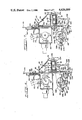
- FIG. 2 is an enlarged front elevational view of a new and improved film duplication system for making one or more duplicates of image areas developed on a master film strip moved in sequence along a master film strip processing path;
- FIG. 3 is a fragmentary front elevational view of the film duplication system showing some of the internal details thereof;
- FIG. 4 is a fragmentary front elevational view of the film duplication system similar to FIG. 3 but illustrating components thereof in a different operative position permitting relative movement between the respective master and duplicate film strips;
- FIG. 5 is a rear elevational view of the film duplication system of the present invention.
- FIG. 6 is a fragmentary, transverse cross-sectional view taken substantially along lines 6--6 of FIG. 3;
- FIG. 7 is a cross-sectional view similar to FIG. 6 taken substantially along lines 7--7 of FIG. 4.
- FIG. 8 is an enlarged front elevational view of a shutter control mechanism in accordance with the present invention.
- FIG. 9 is an enlarged rear elevational view of the shutter mechanism with portions broken away for clarity.
- FIGS. 1 and 2 therein is illustrated in schematic and diagrammatic form, a self-contained microimage recorder system adapted to provide complete microfiche records or film rolls from computer generated images developed initially on a master film strip.
- the self-contained COM (computer output on microfilm) microimage recorder is of the type disclosed in copending U.S. patent application Ser. No. 787,812, filed on Oct. 15, 1985, and incorporated herein by reference.
- the microimage recorder is generally referred to as a whole by the reference numeral 20 and comprises an integral, self-contained unit adapted to provide at a record output port 22, a series of complete, discrete microfiche record cards 24. Each card bears an image pattern corresponding to a sequence of computer generated images which are presented by a cathode ray tube or CRT 26.
- the microimage recorder 20 is housed in a self-supporting enclosure or cabinet 28 having a vertically upstanding base plate or chassis wall 29 that is spaced intermediately between accessible front and rear access doors of the housing (not shown).
- the chassis 29 provides support for the multiple system components of the complete microimage recorder apparatus and divides the cabinet or housing 28 between a film processing section and a control, drive and power section behind the chassis.
- An elongated film strip 30 comprising a master film is moved along a master film processing path as indicated by arrows A in FIGS. 2, 3 and 4 and the path extends between a film supply spool 32 and a film takeup spool 34.
- the supply spool is powered by a drive motor 94 mounted on the rearward side of the chassis 29 and the takeup spool is similarly powered by a drive motor 96, also mounted on the rearward face of the chassis wall.
- the drive motors 94 and 96 are energized to advance or reverse the movement or transport of the master film strip along the master film path and these motors are driven to normally exert and maintain a desired amount of film tension on the film strip, for example, approximately five pounds.
- the supply spool 32 is contained within a light tight cartridge 33 preferably of the type disclosed in copending U.S. patent application Ser. No. 787,836, filed on Oct. 16, 1985, and incorporated herein by reference.
- the master film strip 30 is advanced along the master film processing path (arrows A) through an exposure station 36, a master film developing station 38 and a film duplication station generally designated by the numeral 40 and constructed in accordance with the features of the present invention. Successive developed image areas on the master film strip 30 are positioned at the duplication station ready for a duplicating process wherein one or more duplicate of an image area on the master film is formed on a duplicate film strip 42. Any number of duplicate image areas may be exposed in sequence on the duplicate film strip 42 from a single image area on the master film strip 30 at the duplication station.
- the duplicate film is supplied from a spool carried in a duplicate film supply cartridge 128 and the duplicate film strip is movable in opposite directions along a duplicate film processing path as indicated by double headed arrows B in FIGS. 2, 3 and 4.
- the image area is subsequently developed at a duplicate film developing station designated 46 and after developing, the film is eventually passed to a clearing station generally designated as 48 adjacent the outlet port 22.
- the film strip passes through a cutting station 44 where individual record cards or microfiche cards 24 are produced from the elongated film strip by a knife assembly 140 which effects a transverse cutting of the film strip into individual record cards.
- any selected number of individual microfiche or record cards 24 can be made from a single image area on the master film strip 30 while the master film strip is positioned at the duplication station 40. After a particular image area on the master film strip is duplicated on the duplicate film strip 42 as desired, the master film strip moves or advances along the master film processing path and is eventually wound or taken up on the takeup spool 34 driven by the takeup drive motor 96.
- the master film strip 30 and the duplicate film strip 42 move linearly along their respective continuous paths and at the duplication station 40, these paths all merged together or overlap momentarily so that in a contact printing process, a developed image area on the master film strip at the duplication station may be transferred onto the duplicate film strip in contact therewith by the application of light in a controlled exposure cycle as will be described more fully hereinafter.
- the respective film strips 30 and 42 are movable independently of one another and any selected number of duplicates may be generated from a single image area on the master film strip at the duplication station.
- the master film strip 30 comprises a dry silver, COM type film approximately 105 mm in width such as a No. 8500 film offered by the 3M Corporation.
- This film is highly sensitive to light and has a relatively high film speed.
- the duplicate film strip 42 may comprise a high contrast vesicular type film also exposed by light, developed by heat and cleared by light.
- the duplicate film strip may have a film speed considerably different than that of the master film strip from which initial image areas are reproduced or duplicated.
- the master film strip 30 is processed in the microimage recorder 20 so that a completed film strip includes a sequence of linear arrays contained in discrete image areas which are separated by guard bands providing margins having indexing blips thereon for assisting in the control of the travel or movement of the master film strip along the processing path.
- Each image area may include an array of discrete images or frames which are set up in patterns of rows and columns. In a typical format, a large number of images or frames may be included in each image area and machine or human readable indicia may be provided at a convenient location to identify each of the image areas.
- a pattern or array of images is exposed onto an image area of the master film strip at the exposure station 36 which includes an optics assembly generally designated by the reference numeral 58.
- the optics assembly comprises a lens 60 for focusing light images developed by the cathode ray tube 26 onto the master film strip 30 at the exposure station.
- a movable light shroud or enclosure 62 confines the light from the CRT to a desired region and precise position on the film strip.
- An X-Y positioner 64 moves the lens 60 in sequence to different positions in rows and columns with respect to the film strip to form an array of exposed images in each image area on the film.
- an aperture clamp 66 closes against a lens aperture block 68 to precisely position the master film strip in a proper plane for the exposure.
- the master film strip moves from a spool 32 in the supply cartridge 33 around a roller 27 and past a first film clamp 98 in an advancing direction as indicated by the arrows A. From the first film clamp, the film strip continues around an idler roller 100 and passes an encoding roller 102 as more fully described in the copending U.S. patent application Ser. No. 787,812, previously referred to herein and incorporated by reference. After the film is exposed to images generated by the optics assembly 58, the film strip advances past a second film clamp 106 and around a movable dancer roller 108 which is mounted on the outer end of a dancer arm 122.
- the dancer arm is movable about a pivot axle 124 as biased by a spring 126 in order to provide increased tension on the master film strip to a level somewhat higher than the usual level of approximately five pounds which is normally provided by the motors driving takeup and supply spools 32 and 34.
- the master film strip advances upwardly from the dancer roller 120 towards the master film developing station 38 and preferably this developing station is of the type disclosed in copending U.S. patent application Ser. No. 787,898, filed on Oct. 16, 1985, and incorporated herein by reference.
- the film strip moves over a pair of spaced apart support rollers 110 and 112 which provide support for the film at opposite edges of a previously exposed latent image area thereon which is to be developed by the application of heat.
- a developer shoe 70 having a heated, convexly curved contact surface is mounted on a pivot arm 76 rocked or pivoted back and forth by a shaft 75 to move the developer shoe into and out of heating contact with the segment of the master film strip positioned across the rollers 110 and 112.
- a heat shield 72 is provided to protect the master film from unwanted heat during movement of the film strip before and after the controlled heat development of an image area thereon.
- the heat shield is supported on a pivot axle 73 and is interconnected mechanically with the developer shoe to move between a heat shielding position and a retracted position as the developer shoe is moved between a remote position as shown in FIGS. 1 and 2 and a developing position in direct heating contact against the film strip.
- a backup member 80 is provided at the master film developing station 38 for insulating the underside of the master film strip during the heat developing process while the devloper shoe is in direct contact with the film surface, and reference should be had to the detailed disclosure of the aforementioned copending U.S. patent application Ser. No. 787,898, for a more detailed description of the operating processes and structural apparatus of the master film developing station.
- the film is advanced upwardly around a roller 114 and then moves downwardly along a sloping path leading to a duplication position at the duplication station 40.
- the master film remains in the duplication position while one or more duplicates of the developed image areas thereon are made.
- the film strip is advanced around a guide roller 116 and upwardly past a third film clamp 118 and guide roller 121 to be wound upon the takeup spool 34 driven by the takeup drive motor 96.
- the master film strip 30 moves from the supply cartridge 33 to the takeup reel 34 in a film advancing direction as indicated by the arrows A, however, if it is desired, the master film strip can be returned to the supply spool 32 in the cartridge 33 at any time, usually when a length of a master film strip has been fully exposed, developed and duplicated as desired.
- the duplicate film strip 42 is fed from the duplicate film supply cartridge 128 by a pair of feed rollers 130 and moves around a dancer roller 134 mounted adjacent the outer end of dancer arm 154 supported for pivotal movement about a pivot axle 156.
- the duplicate film strip then passes upwardly from the dancer roller 136 around a roller 136 and downwardly to the duplication station 40 wherein a segment of the master film processing path and a segment of the duplicate film processing path converge and overlap to provide for a contact printing type duplication process wherein an image area on the master film strip 30 is duplicated on the duplicate film strip 42.
- the respective film strips 30 and 42 are clamped tightly together (FIGS.
- a vacuum clamp and film transport assembly 82 which includes an endless, perforated belt 84 trained around an idler roller 86 at one end and a drive roller 88 at a lower opposite end.
- the duplicate film strip 42 is always firmly secured against the upper run of the vacuum belt 84 by a vacuum drawn from the underside of the movable belt and thus the duplicate film strip may be moved independently relative to the master film strip 30 in reversible, opposite directions as indicated by the arrows B.
- the drive roller 88 is mounted on a drive shaft 90 which projects transversely through the chassis plate 29 and is coupled to a reversible, DC powered drive motor 91 mounted on the rear face of the chassis as shown in FIG. 5.
- the vacuum clamp assembly 82 is pivotally movable around the axis of the drive shaft 90 between a film clamping position as shown in FIGS. 2, 3 and 6 for duplicating an image area on the master film 30 onto the duplicate film strip 42 and a lower, non-clamping, separate position as shown in FIGS. 1, 4 and 7 wherein the previously merged segments of the respective master film and duplicate film processing paths are spaced apart and separated from one another.
- the duplicate film stip 42 can be moved to advance or in a reverse direction as driven by the endless vacuum belt 84 while a particular image area on the master film strip 30 remains in a duplication position without moving.
- a selected image area on the master film strip may be duplicated successively any number of times on the duplicate film strip by advancement of the duplicate film strip after each exposure cycle while the master film strip is stationary.
- the film strip is advanced outwardly past the rollers 116, 88 and a roller 138 to the cutting station 44 wherein a cutting knife assembly 140 is activated to sever the duplicate film strip into discrete record segments or microfiche cards 24.
- the cards are fed by a pair of feed rollers 142 and 144 to a duplicate film developing station 46 wherein the latent image area on each individual microfiche or record card 24 is developed by the application of heat from a rotating heated drum 146.
- the individual microfiche or record cards 24 are biased against the surface of the heated drum by an endless pressure belt 148 and the developed microfiche cards then pass from the developing station 46 between a pair of endless feed belts 150 and 152 to the exit port 22.
- a clearing station 48 is associated with the exit port and includes a clearing lamp 159 which provides film clearing, light radiation directed onto each of the developed microfiche records or cards 24 as the card is discharged from the belt feeders 150 and 152 into a tray at the exit port 22.
- the duplication station 40 includes an electric exposure lamp 161 which is capable of providing several different levels of illumination depending upon the power supplied thereto.
- the exposure lamp is mounted in a light tight lamp housing or enclosure 163 detachably secured to a rear face of a shutter enclosure 164 mounted on the back face of the chassis wall 29.
- a portion of the shutter housing is positioned directly opposite the light housing 92 mounted on the forward face of the chassis as best shown in FIGS. 6 and 7.
- the electric lamp 161 is removably mounted within the lamp housing 163 and is supported at opposite ends in sockets 166 mounted on the end walls of the enclosure. The lamp and enclosure may be removed from the shutter housing as a unit for servicing and or replacement of the lamp.
- Power for illuminating the filaments of the lamp 161 is supplied through electrical cables 168 and the level of power provided and the time of an exposure interval is closely controlled and selected to provide the desired amount of light intensity for exposing and forming a duplicate image area on the duplicate film strip 42 from the image area in contact therewith on the master film strip 30 at the duplication station.
- cooling air flows into the housing through a suitable inlet 169 as indicated schematically by the arrows C and heated air is exhausted from the lamp enclosure 163 through exhaust outlet 170 in an upper wall thereof via an exhaust hose 172 as indicated by the arrows D (FIGS. 6 and 7).
- controlled intensity light travels as indicated by the arrows E (FIG. 6) through an open, rectangular shaped shutter aperture 29a that is formed in the vertical chassis wall 29 directly between the light enclosure 92 and the shutter compartment 164.
- the light generated by the illuminated lamp 161 strikes a mirror 174 mounted on a sloping upper wall portion of the light housing 92 as shown in FIG. 6, and is reflected downwardly through a clear glass platen 93 forming a bottom wall of the housing to expose a duplicate image area on the duplicate film strip 42 that is clamped directly beneath a developed image area on the master film strip 30 in place at the duplication station.
- the platen 93 is removably mounted in the light housing structure 92 and can be taken out for cleaning and replacement by releasing a clip mechanism 176 along an outer lower edge portion of the housing as shown in FIGS. 2, 6 and 7.
- the flow of light from the lamp 161 through the aperture 29a is closely and accurately controlled by a relatively fast moving swinging shutter 180 which is mounted in the shutter housing 164 on the rear face of the chassis 29.
- the swinging shutter is supported for pivotal movement by a shutter shaft 182 and is movable between an open position and a closed position wherein the shutter is positioned directly in front of the aperture 29a for blocking the flow of light from the lamp 161 through the aperture.
- the shaft 182 which supports the swinging shutter 180 is mounted for rocking movement on a bearing structure 184 carried on the front of the chassis 29 as indicated generally in FIG. 2.
- the swinging shutter 180 is adapted to rest in either a fully closed position or a fully open position and an over-center spring 201 (FIG. 9) is provided to retain the shutter against either one of a pair of bumper stops 203L or 203R mounted on divergent edge walls 164b and 164c of the shutter housing 164.
- An upper end oi the spring 201 is connected to a fixed pin 205 mounted on the back wall 164a of the shutter housing and the lower end of the spring is connected to a short pin 180a mounted on the shutter itself.
- the spring 201 becomes effective to bias and hold the shutter against one of the bumper stops 203L or 203R.
- each bumper stop is mounted on stop arms 207 which in turn are pivotally mounted on the chassis wall 29.
- the stops and arms serve as shock absorbers to arrest the movement of the shutter 180 at the end of each swinging stroke toward the open or closed position.
- each bumper stop is provided with a backup stop retainer assembly 209 and together the bumper stops 203, stop arms 207 and stop retainers 209 provide smooth deceleration of the shutter at the end of each operative stroke or shutter swing.
- a shutter control mechanism 211 which includes a left hand shutter opening solenoid 186 and a right hand, shutter-closing solenoid 188, both of which are mounted on the front face of the chassis wall 29 on opposite sides and above the level of the shutter shaft 182 as shown in FIGS. 2 and 9.
- the shutter shaft is supported for rocking motion to swing the shutter back and forth between open and closed positions on the bearing structure 184 and a drum 196 is mounted on the shutter shaft to rotate the shaft in opposite directions.
- the drum is rotated in a clockwise direction, the shutter 180 swings from the open position (FIG. 8) resting against the stop 203R (FIG.
- the shutter control mechanism 211 includes a pair of flexible cords 192L and 192R each connected at a lower end to the drum and secured within respective slots 196L and 196R, provided in the drum. From the lower slot 196L, the cord 192L passes around a left hand grooved portion in the drum 196 in a clockwise direction and then is trained around a grooved right hand edge portion of a pulley wheel 190R.
- the wheel 190R is mounted on an outer end portion of a pull-in type armature of the shutter closing solenoid 188.
- the line 192L continues upwardly and to the left from the pulley wheel 190R and passes through an aperture provided in a cable guide element 193L for attachment to a cord stop 195L as shown in FIG. 8.
- the stop 195L is attached to one end of a tension spring 194L and the spring has an opposite end fixedly secured to the chassis wall 29 by a fastener as shown.
- a cord 192R extends upwardly from the slot 196R in the drum around a right hand portion of the drum in a counterclockwise direction and passes around a grooved left hand edge portion of a pulley wheel 190L on the pull-in type armature of the shutter opening solenoid 186.
- both solenoids 186 and 188 are in a deenergized state, and assuming that the shutter 180 in the open position (FIG. 8), the tension spring 194L is extended and the stop 195L is closely adjacent the cable guide element 193L as shown.
- the left hand cord 192L exerts tension on the left hand spring 194L causing the spring to extend from a contracted position to the fully extended condition of FIG. 8 wherein the stop 195L is closely adjacent the left hand cable guide 193L as illustrated. Subsequent deenergization of the solenoid 186 permits the tension spring 194R to contract and pull the left hand pulley 190L outwardly by pulling through the cord 192R.
- the system 211 permits the armatures of the respective solenoids 186 and 188 to always return to the fully extended outward positions as shown when niether solenoid is being energized.
- One of the springs 192L or 192R is extended in this condition so that whichever of the two solenoids is energized, the energized solenoid only has to swing the shutter 180 and does not have to simultaneously stretch or extend the extended one of the springs 192L and 192R. Speed of shutter movement between the open and closed positions is thus maximized.
- the lamp 161 is maintained at a relatively low power level, for example 250 watts, as the shutter swings between the closed position and the open position. Both shutter traverses are made at reduced lamp intensity so that illumination gradients on the film are minimized. As viewed in FIGS. 3 and 4, the left hand portion of each image area 50 will inherently receive more lights, due to the opening swing of the shutter from left to right and the closing swing from right to left. By making both traverses of the shutter from open to closed and from closed to open at reduced levels of illumination, the difference in illumination exposure as a percentage of the total illumination is minimized. When the shutter is fully open, the lamp 161 is energized at a higher level, for example 500 watts, until the exposure cycle times out.
- a relatively low power level for example 250 watts
- the duplication station 40 is also provided with a second, safety shutter 200 mounted on the opposite or forward face of the chassis 29 to slide within a pair of parallel upwardly sloping side frame members 202 which guide the reciprocal sliding movement of the safety shutter between an upper, aperture closing position (FIGS. 4 and 7) and a downward, shutter opening position illustrated in FIGS. 3 and 6.
- the shutter guides or tracks 202 are mounted on opposite sides of the aperture 29a and slope downwardly and leftwardly of the aperture for guiding reciprocal movement of the safety shutter between the open and closed positions in a direction indicated by the arrow G.
- the sliding safety shutter 200 prevents inadvertent exposure and/or double exposures of the master and duplicate film strips during movement of the film in advancing or reversing directions and, in addition, the safety shutter 200 permits servicing of the swinging shutter 180 and the lamp 161 and removal of the lamp enclosure 163 from the rear section of the housing 28 without having to remove the film strips in the apparatus in the front section of the housing on the other side of the vertical chassis 29. Removal of the lamp enclosure 163 and the swinging shutter housing 164 can be accomplished without fear that film present on the vacuum clamp 82 above the vacuum belt 84 will be exposed in an unwanted fashion.
- the sliding shutter 200 is driven to reciprocate within the side guides 202 by a drive arm 204 pivotally connected to a rearwardly extending shutter bracket 200a projecting through a slotted portion 29b formed in the chassis wall as best shown in FIGS. 6 and 7.
- a rearward end of the drive arm 204 is pivotally secured on a pivot pin 206 spaced outwardly from the rearward face of the chassis 29 and supported in a motor bracket 208 detachably mounted on the rear face of the chassis.
- a DC motor 210 for supplying power for reciprocating the shutter 200 and for operating the vacuum clamp assembly 82 in synchronism therewith is supported by the motor bracket 208, and the motor includes an output shaft 210a which drives a pinion 212 in meshing engagement with a larger diameter, driven gear 214.
- the gear is mounted for rotation at a reduced speed on a gear shaft 216 journalled in bearings carried by the motor bracket 208 and the shaft extends parallel of the motor shaft 210a as shown in FIGS. 6 and 7.
- An eccentric crank pin 218 extending outwardly from one face of the gear 214 is drivingly engaged with the arm 204 in an elongated slot 204a extending longitudinally of the body of the arm and intermediate the ends.
- the shutter drive arm 204 is pivoted to rock back and forth between a lower position (FIG. 6) wherein the shutter 200 is in an open position and an upper position (FIG. 7) wherein the shutter is in a closed position covering the aperture 29a.
- the DC motor 210 also provides driving power through the gear 214 for synchronizing movements of the vacuum clamp assembly 82 between an upper, film clamping position (FIGS. 2, 3 and 6) and a lower retracted position wherein the duplicate film strip 42 is separated from contact with the master film strip 30 as illustrated in FIGS. 4 and 7.
- the gear 214 is provided with an eccentric, generally circular cam 220 on a face opposite the crank pin 218 and the cam engages a cam follower roller 222 mounted on the rearward end of a drive arm 224, for controlling the position of the vacuum clamp assembly 82.
- the drive arm 224 is pivotally supported intermediate its ends for rocking movement on a pin 226 carried on a bracket 208a.
- the arm 224 extends forwardly through the wall slot 29b and is connected to a universal joint 228 joined to a link member 230 of adjustable length pivotally connected at the upper end to a clevis 232 depending downwardly from the underside of the vacuum clamp assembly 82 as shown best in FIGS. 2, 3, 4, 6 and 7.
- the vacuum clamp assembly 82 serves to clamp and hold the duplicate film strip 42 tightly against the surface of the upper run of the perforated vacuum belt 84 so that the film strip will move therewith and may be indexed in either direction as shown by the arrows B to position a particular segment thereof in position for imaging as previously described.
- the vacuum clamp assembly serves as a clamp for biasing the duplicate film strip against the master film strip and both film strips together tightly against the glass platen 93 so that a true and accurate image area can be exposed and duplicated on the duplicate film strip when exposed to light from the lamp 161 passed through a developed image area on the master film strip as previously described.
- the vacuum clamp assembly includes a channel-shaped outer body 234 with the clevis 232 attached to the underside thereof and the body is mounted for pivotal movement at a lower end on the pivot shaft 90 which drives the lower belt drive roller 88.
- the outer body supports a shaft for the idler roller 86 and between the upper and lower runs of the endless, perforated belt 84 there is provided a central vacuum chamber 236 having a bottom wall, a pair of upstanding sidewalls and a pair of opposite end walls which form an open upper end closed off by the upper run of the perforated vacuum belt 84.
- a vacuum is drawn in the chamber 236 through an outlet fitting 238 projecting outwardly from an outer sidewall through a vacuum hose 240 of flexible construction connected to a vacuum pump or fan (not shown).
- a vacuum pump or fan not shown
- suction is provided on the vacuum hose, the duplicate film strip 42 is clamped tightly against the upper run of the perforated vacuum belt 42 and is held against the belt for movement therewith in either direction as indicated by the double headed arrow B.
- the direction of belt movement is determined by the direction of rotation of the shaft 90 driven by the drive motor 91 which is a DC powered bi-directional motor.
- the drive motor 91 is energized to rotate in one direction for advancing the duplicate film strip 42 in successive steps after each duplicate microfiche record of an image area 50 is exposed. Any number of duplicates can be made from a single image area on the master film strip 30. After a final step of advancement, the exposed image area on the duplicate film strip reaches a null position with the leading edge of the strip at the cutting station 44. The duplicate film strip is advanced an additional step so that the exposed image area passes by the knife mechanism 140 into a position for cutting thereby to provide an individual microfiche record 24.
- a delay period is provided equivalent to the time required for each duplication of multiple image areas from a single master film image area in order that consistent delay time and image quality are obtained. After the delay period, the exposed image area of the duplicate film is cut, developed and cleared.
- the master film strip 30 is not advanced and exposure and master film developing operations are not carried out between successive operations of the duplication station 40.
- a first image area is exposed on the duplicate film strip 42 at the duplication station, and the duplicate film strip is advanced to the position shown in FIG. 1 with the leading edge at the cutting station 44. While the first latent or undeveloped image area at the leading end of the duplicate film strip 42 is at this null position between the duplication station and the cutting station 44, the duplication station 40 is operated again to duplicate a second copy of the same image area 50 from the master film strip 30 onto the next adjacent region of the duplicate film strip 42.
- the duplicate film strip is advanced one step to move the first exposed image area past the knife member 140 of the cutting station 44.
- This first exposed image area is severed from the end of strip 42, and is developed and cleared to provide a completed microfiche record 24.
- This sequence of operation is repeated without movement of the master film strip 30 until the desired multiple number of records are duplicated.
- the time required between operations of the duplication station 40 is longer when the master film strip 30 is advanced and processed at the exposure station 36 and developing station 38 between operations of the duplication station 40.
- the image quality of exposed image areas on the duplicate film 42 is affected by the delay between exposure and development of the duplicate film 42. Consistent image quality is obtained by controlling the duplicate film travel to prevent extended delay as the master film strip 30 is advanced and processed.
- the duplicate film strip 42 is advanced one step following the duplication operation to place the exposed image area on the duplicate film strip 42 at the null position with the leading edge at the cutting station 44.
- the duplicate film strip is then advanced an additional step so that the exposed image has passed the cutting station and the exposed image area is properly positioned to be cut from the end of strip 42.
- a delay period is provided equivalent to the time required for each duplication of multiple image areas from a single master film image area in order that consistent delay time and image quality are obtained. After the delay period, the exposed image area of the duplicate film is cut, developed and cleared.
- an unexposed area resides in the null position of the duplicate film path between the duplication station 40 and the cutting station 44. Wastage of this unexposed area is avoided by reversing the travel of the duplicate film strip to retract the unexposed leading end of the duplicate film strip into the duplication station 40.
- the drive motor 91 is energized to rotate the shaft 90 in a reverse direction and the vacuum belt 84 is moved in the reverse direction to retract the duplicate film strip one step.
- the dancer roller 134 is mounted on an arm 154 pivoted at axis 156.
- the weight of the arm 154 causes the dancer roller 134 to take up slack in the duplicate film strip 42 when it is retracted.
- a pair of detectors in the form of switches 160 and 162 detect alternate extreme positions of the arm 154 and dancer roller 134. If duplicate film strip tension is lost as by breakage of the film strip 42, the arm 154 moves against switch 162 to provide a signal indicating a film break.
- Switch 160 controls the duplicate film strip drive rollers 130 to feed additional film strip 42 into the duplicate film strip path upon demand.
- the drive motor 210 is a unidirectional DC motor and rotates the gear 214 only in one direction. This gear drives both the interconnected shutter drive arm 204 and the vacuum drive arm 224, respectively, to rock back and forth to provide synchronized, reciprocal bi-directional movement of the safety shutter 200 and the vacuum clamp assembly 82.
- the unique drive mechanism which is powered from a single uni-directional power source insures that when the safety shutter 200 is in a closed position, the vacuum clamp assembly 82 is in an unclamped downward position, and that alternatively, when the safety shutter is in an open position, the vacuum clamp assembly is in a film clamping position ready for creating a duplicate image area on the duplicate film strip 42 in the duplicating position at the duplicating station 40.
- the drive motor 210 is energized, if necessary, to move the safety shutter 200 upwardly to the closed position and simultaneously as this occurs the vacuum clamp assembly 82 is released downwardly to the nonclamping position so that the master film strip 30 and the duplicate film strip 42 may be moved and transported independently of one another by the respective film transporting systems.
- a typical operating sequence of the duplicator station 40 takes place as follows as more fully described in the copending U.S. patent application Ser. No. 893,750, filed Aug. 6, 1986.
- a machine control unit performs the following operations including energizing a latch solenoid for the duplicate film dancer roller 134, reversing the drive motor 91 one full cycle to retract the duplicate film strip 42, clamping the master film strip 30 and the duplicate film strip 42 against the platen 93 which opens the sliding shutter 200, opening the swinging shutter 180, waiting for a swinging shutter 180 open signal and simultaneously starting a vibration timer and starting an exposure timer.
- the duplication lamp 161 is energized by operating a pair of relays at a high power level, for example 500 watts to provide a high light intensity output. After a predetermined exposure time period, the duplication lamp 161 is provided with the normal maintenance power level, for example 250 watts, and the swinging shutter 200 is closed a predetermined time thereafter allowing the lamp 161 to dim to the low light level.
- the master film 30 and duplicate film 42 are unclamped from the platen 93.
- the duplicate film strip 42 is advanced one step and the duplicate film dancer latch solenoid is deenergized. After a predetermined time delay the duplicate fiche is cut by activating the knife member 140 to form the individual microfiche 24.
- the MCU repeats the sequential duplication steps until all duplicates for the current master fiche on an image area of the master film strip 30 in the duplication position are produced.
Landscapes
- Physics & Mathematics (AREA)
- General Physics & Mathematics (AREA)
- Projection-Type Copiers In General (AREA)
Abstract
Description
Claims (34)
Priority Applications (1)
| Application Number | Priority Date | Filing Date | Title |
|---|---|---|---|
| US06/788,283 US4626099A (en) | 1985-10-17 | 1985-10-17 | Film duplication system for microimage recorders |
Applications Claiming Priority (1)
| Application Number | Priority Date | Filing Date | Title |
|---|---|---|---|
| US06/788,283 US4626099A (en) | 1985-10-17 | 1985-10-17 | Film duplication system for microimage recorders |
Publications (1)
| Publication Number | Publication Date |
|---|---|
| US4626099A true US4626099A (en) | 1986-12-02 |
Family
ID=25144013
Family Applications (1)
| Application Number | Title | Priority Date | Filing Date |
|---|---|---|---|
| US06/788,283 Expired - Fee Related US4626099A (en) | 1985-10-17 | 1985-10-17 | Film duplication system for microimage recorders |
Country Status (1)
| Country | Link |
|---|---|
| US (1) | US4626099A (en) |
Cited By (6)
| Publication number | Priority date | Publication date | Assignee | Title |
|---|---|---|---|---|
| US4724469A (en) * | 1986-03-14 | 1988-02-09 | Fuji Photo Film Co., Ltd. | Image recording apparatus |
| US4843435A (en) * | 1987-04-13 | 1989-06-27 | Fuji Photo Film Co., Ltd. | Conveyor of a copying apparatus |
| US5068688A (en) * | 1988-03-03 | 1991-11-26 | Brother Kogyo Kabushiki Kaisha | Device for automatically loading an image recording apparatus with a recording medium |
| US5313248A (en) * | 1990-05-24 | 1994-05-17 | Seiko Epson Corporation | Heat protection of photosensitive elements in image formation apparatus |
| US5563867A (en) * | 1994-06-30 | 1996-10-08 | Discovision Associates | Optical tape duplicator |
| CN110216867A (en) * | 2018-03-02 | 2019-09-10 | 丰田自动车株式会社 | Film feeding device, film conveying method and apparatus for film adhesion |
Citations (2)
| Publication number | Priority date | Publication date | Assignee | Title |
|---|---|---|---|---|
| US2515420A (en) * | 1944-12-02 | 1950-07-18 | Prismacolor Inc | Film printing machine |
| US3768906A (en) * | 1971-12-27 | 1973-10-30 | Producers Service Corp | Method and apparatus for printing and processing thermal film |
-
1985
- 1985-10-17 US US06/788,283 patent/US4626099A/en not_active Expired - Fee Related
Patent Citations (2)
| Publication number | Priority date | Publication date | Assignee | Title |
|---|---|---|---|---|
| US2515420A (en) * | 1944-12-02 | 1950-07-18 | Prismacolor Inc | Film printing machine |
| US3768906A (en) * | 1971-12-27 | 1973-10-30 | Producers Service Corp | Method and apparatus for printing and processing thermal film |
Cited By (7)
| Publication number | Priority date | Publication date | Assignee | Title |
|---|---|---|---|---|
| US4724469A (en) * | 1986-03-14 | 1988-02-09 | Fuji Photo Film Co., Ltd. | Image recording apparatus |
| US4843435A (en) * | 1987-04-13 | 1989-06-27 | Fuji Photo Film Co., Ltd. | Conveyor of a copying apparatus |
| US5068688A (en) * | 1988-03-03 | 1991-11-26 | Brother Kogyo Kabushiki Kaisha | Device for automatically loading an image recording apparatus with a recording medium |
| US5313248A (en) * | 1990-05-24 | 1994-05-17 | Seiko Epson Corporation | Heat protection of photosensitive elements in image formation apparatus |
| US5563867A (en) * | 1994-06-30 | 1996-10-08 | Discovision Associates | Optical tape duplicator |
| CN110216867A (en) * | 2018-03-02 | 2019-09-10 | 丰田自动车株式会社 | Film feeding device, film conveying method and apparatus for film adhesion |
| CN110216867B (en) * | 2018-03-02 | 2021-11-09 | 丰田自动车株式会社 | Film conveying device, film conveying method, and film sticking device |
Similar Documents
| Publication | Publication Date | Title |
|---|---|---|
| US4626099A (en) | Film duplication system for microimage recorders | |
| US4624558A (en) | Microimage recorder | |
| US2478641A (en) | Document-operated camera control | |
| US4653890A (en) | Film developing system for microimage recording apparatus | |
| US3240115A (en) | Photographic apparatus | |
| US3408144A (en) | Film advancing means | |
| CA2146385C (en) | Film cartridge carrier | |
| EP0123053A1 (en) | A film feeder of cassetteless X-ray photographic apparatus | |
| US3374723A (en) | Automatic electrical control apparatus and film printer cuing system embodying same | |
| US3820892A (en) | Double reel apparatus for electrostatically producing copies and matrices | |
| US2512486A (en) | Fore-and-aft aerial camera | |
| US3730616A (en) | Cinematographic apparatus | |
| US4501487A (en) | Microfiche recording apparatus and method with stationary film head | |
| CA1160878A (en) | Microfiche recording system | |
| US4518241A (en) | Installation for supplying photographic emulsion carriers to a developing machine | |
| US3990789A (en) | Projecting system for automatically loading, threading projecting and rewinding a plurality of films in casettes | |
| US4970548A (en) | Image recording apparatus | |
| US3733118A (en) | Film training projector | |
| US5661542A (en) | Apparatus and method of recording an image in which the developing material is held, pressed, heated, and conveyed | |
| EP0028148B1 (en) | Process and apparatus for photographically enlarging and developing an image | |
| JP2552183B2 (en) | Search device | |
| US4402597A (en) | Filmstrip for preventing fogging of intermediate film in microfiche recording systems | |
| US3775711A (en) | Micro film duplicating device | |
| EP0506114B1 (en) | Scanning exposure apparatus | |
| US4699504A (en) | Control system for microimage recorders |
Legal Events
| Date | Code | Title | Description |
|---|---|---|---|
| AS | Assignment |
Owner name: BELL & HOWELL COMPANY, CHICAGO, IL. A CORP. OF DE. Free format text: ASSIGNMENT OF ASSIGNORS INTEREST.;ASSIGNORS:ZUELKE, ROBERT D.;FRIEDRICH, PAUL H.;STITES, DAVID G.;REEL/FRAME:004482/0609;SIGNING DATES FROM 19851017 TO 19851105 |
|
| CC | Certificate of correction | ||
| FPAY | Fee payment |
Year of fee payment: 4 |
|
| AS | Assignment |
Owner name: BANKERS TRUST COMPANY, AS AGENT, NEW YORK Free format text: ASSIGNMENT OF ASSIGNORS INTEREST;ASSIGNOR:BELL & HOWELL COMPANY A CORP. OF DE;REEL/FRAME:006673/0133 Effective date: 19930817 |
|
| REMI | Maintenance fee reminder mailed | ||
| LAPS | Lapse for failure to pay maintenance fees | ||
| FP | Lapsed due to failure to pay maintenance fee |
Effective date: 19941207 |
|
| AS | Assignment |
Owner name: BELL & HOWELL OPERATING COMPANY, ILLINOIS Free format text: RELEASE OF PATENT COLLATERAL ASSIGNMENT AND SECURITY AGREEMENT;ASSIGNOR:BANKERS TRUST COMPANY, A NEW YORK BANKING CORPORATION;REEL/FRAME:008783/0351 Effective date: 19970922 |
|
| STCH | Information on status: patent discontinuation |
Free format text: PATENT EXPIRED DUE TO NONPAYMENT OF MAINTENANCE FEES UNDER 37 CFR 1.362 |