US461459A - Weed and grass cutter - Google Patents
Weed and grass cutter Download PDFInfo
- Publication number
- US461459A US461459A US461459DA US461459A US 461459 A US461459 A US 461459A US 461459D A US461459D A US 461459DA US 461459 A US461459 A US 461459A
- Authority
- US
- United States
- Prior art keywords
- bar
- shaft
- crank
- cutting apparatus
- weed
- Prior art date
- Legal status (The legal status is an assumption and is not a legal conclusion. Google has not performed a legal analysis and makes no representation as to the accuracy of the status listed.)
- Expired - Lifetime
Links
- 244000025254 Cannabis sativa Species 0.000 title description 8
- 241000196324 Embryophyta Species 0.000 title description 4
- 241000968352 Scandia <hydrozoan> Species 0.000 description 2
- HJGMWXTVGKLUAQ-UHFFFAOYSA-N oxygen(2-);scandium(3+) Chemical compound [O-2].[O-2].[O-2].[Sc+3].[Sc+3] HJGMWXTVGKLUAQ-UHFFFAOYSA-N 0.000 description 2
- RSMUVYRMZCOLBH-UHFFFAOYSA-N metsulfuron methyl Chemical compound COC(=O)C1=CC=CC=C1S(=O)(=O)NC(=O)NC1=NC(C)=NC(OC)=N1 RSMUVYRMZCOLBH-UHFFFAOYSA-N 0.000 description 1
Images


Classifications
-
- A—HUMAN NECESSITIES
- A01—AGRICULTURE; FORESTRY; ANIMAL HUSBANDRY; HUNTING; TRAPPING; FISHING
- A01D—HARVESTING; MOWING
- A01D34/00—Mowers; Mowing apparatus of harvesters
- A01D34/835—Mowers; Mowing apparatus of harvesters specially adapted for particular purposes
- A01D34/86—Mowers; Mowing apparatus of harvesters specially adapted for particular purposes for use on sloping ground, e.g. on embankments or in ditches
- A01D34/866—Mounting means
Definitions
- This invention relates to track-clearers, and aims to provide a simple and efficient machine for removing grass, weeds, and other growth from the bed of a railroad-track.
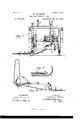
- Figure l is a perspective View, parts being broken away, of a machine embodying my invention.
- Fig. 2 is a plan View just beneath the platform of the car or vehicle.
- Fig. 3 is a front view of the machine.
- Fig. 4 is a rear view of the cutting apparatus.
- Fig. 5 is a detail view of theleaders or guards on the cutterbar.
- Fig. 6 is a detail view of the shoe.
- Fig. 7 is a detail view of the gear-wheel and cl u tch on the axle. gearing intermediate the crank-shaft which drives the cutting apparatus and the gearwheel on the axle.
- 12 indicates the platform of the truck or vehicle, which is mounted on the axles S 8, which have the supporting-wheels 9 9 at their ends.
- the frame which carries the cutting apparatus and the mechanism for transmitting motion from the axle to the said cutting apparatus is com posed of the parallel side bars 13 13, end bars 14 and 15, connecting the side bars 13 at their ends, and the curved bar 16, the latter being located at the front end of the said frame.
- a set of gearing is placed upon the axle of the-car, truck, or platform of a vehicle, which, when the car orvehicle is in motion, will give motion to the sickle-bars.
- the finger-bar A is constructed with an arch N at a point immediately over the rail, which permits the sickles to drop one or more inches below the top of Fig. 8 is a detail view of the B of the sickle is connected with the pitmanpin D of the inner sickle B, the inner sickle being driven by a pitrn'an C, which is connected with the crank-shaft E, which is journaled near its ends in the end bars 14 and 15.
- the inner'portion of finger or guard-bar A" is bent to an :ngle, so as to conform to the contour of the track between the rails.
- a guard or leader F which performs two func-' tionsto keep the finger or guard bar A in one position over the rail and to lead the weeds and grass from the rail into the knives orsickle to be out thereby.
- a runner or shoe On the outside portion of finger or guard bar A, intermediate its ends, there is placed a runner or shoe 0, for the purpose of carryingsaid bar A over obstacles.
- Attached to barA is a chain G or its equivalent, connected with a crank it at the end of rock-shaft H to enable the operator to raise and lower said bar at will.
- Rock-shaft H is placed on the platform of the car or vehicle and has connections by a chain I with frame or support of crank-shaft E, which enables the operatorto raiseand lower crank-shaft and barA at will, the chain I being attachedto crank h at the end of the rockshai't.
- an upright handle J Connected to rock-shaft H is an upright handle J, supported by a curved brace K, having notches or teeth which receive a catch or stop P, placed onhandle J for the purpose of holding the finger-bar A and crankshaft E in any desired position.
- a rod or bar Q Projecting downward from the top of the platform is a rod or bar Q, with its lower end near the top of the rail, so formed asto make a seat or rest for bar A, said bar Q passing through the arch or curve N of the bar A, holding it in position while the machineis in motion.
- WVheel R is placed upon axle of the car and I has a clutch S attached for the purpose of enabling the operator to throw the machine in and out of gear at will by use of lever T, which is pivoted at t to the bracket 15, which is pro jected from a side bar 13 of the crank-shaftsupporting frame.
- Wheel R is connected to shaft'U with pinion V and meshes into the same;
- pinion X meshing into pinion X, which is placed upon crank-shaft E.
- lever 1 pivoted at 1 to bracket 1, and which is connected with clutch to, splined on the shaftUto move the clutch w to and from the clutch-pinion W, which enables the operator to throw the same in and out of gear or mesh at will.
- hook 4 Used for the purpose of holding bar up when not used. Said hook 4 is caught by chain 5 to hold said bar up whenever desired.
- This machine may be worked by either man or horse or steam power, as may be desired. It can be made to cut the weeds and grass on each side of the track at the same time by placing-cutting mechanism on each axle.
- Axles 8 8 and wheels 9 9 9 9 are used for the purpose of driving the machinery.
- a cutting apparatus having a yoke or arch to straddle the rail, substantially as and for the purpose described. 7
- the combination with the cutting apparatus having a portion on each side of the rail and a yoke or arch spanning the rail and connecting the two portions of the cutting apparatus, of a pitman connecting the inner portion of the cutting apparatus with a crank-shaft, and a second pitman connecting the outer portion of thecutting apparatus with the inner end of the aforesaid pitman, substantially as described.
- a cutting apparatus having an arch to straddle the'rail, the inner portion of the said cutting apparatus being bent up at an angle, substantially as described.
Landscapes
- Life Sciences & Earth Sciences (AREA)
- Environmental Sciences (AREA)
- Harvester Elements (AREA)
Description
3 Shets-Sheet 1.
R E T .T m ES m L Aw W. M B E w (No Model.)
,459. Patented Oct. 20, 1891.
(No Model.) 3 Sheets-Sheet 2.
W. WALKER;
WEED AND GRASS CUTTER. No. 461,459. Patented Oct. 20, 1891.
PVaM
llllll- F EEIM my (No Model.) 7 3 Sheets-Sheet 3. t W. WALKER. WEED AND GRASS CUTTER.
N0. 461 ,459. Patented O0t.20, 1891.
A llllllilllll llw 11i! I'w nmmm UNITED STATES PATENT OFFICE.-
IVILLIAM IVALKER, OF SCANDIA, KANSAS. 1
WEED AND GRASS CUTTER.
SPECIFICATION forming part of Letters Patent No. 461,459, dated October 20, 1 891.
. Application filed August 19, 1890. Serial No. 362,430. (No model.)
To aZZ whom, it may concern.-
- Be it known that I, WILLIAM WALKER, a citizen of the United States, residing at Scandia, in the county of Republic andState of Kansas, have invented certain new and useful Improvements in lVeed and Grass Cutters; and I do hereby declare the following to be a full, clear, and exact description of the invention, such as will enable others skilled in the art to which it appertains to make and use the same.
This invention relates to track-clearers, and aims to provide a simple and efficient machine for removing grass, weeds, and other growth from the bed of a railroad-track.
The improvement consists of the novel mechanism and devices which hereinafter will be more fully described and claimed, and which are shown in the annexed drawings, in which Figure l isa perspective View, parts being broken away, of a machine embodying my invention. Fig. 2 is a plan View just beneath the platform of the car or vehicle. Fig. 3 is a front view of the machine. Fig. 4 is a rear view of the cutting apparatus. Fig. 5 is a detail view of theleaders or guards on the cutterbar. Fig. 6 is a detail view of the shoe. Fig. 7 is a detail view of the gear-wheel and cl u tch on the axle. gearing intermediate the crank-shaft which drives the cutting apparatus and the gearwheel on the axle.
In the present drawings, 12 indicates the platform of the truck or vehicle, which is mounted on the axles S 8, which have the supporting-wheels 9 9 at their ends. The frame which carries the cutting apparatus and the mechanism for transmitting motion from the axle to the said cutting apparatus is com posed of the parallel side bars 13 13, end bars 14 and 15, connecting the side bars 13 at their ends, and the curved bar 16, the latter being located at the front end of the said frame.
In constructing this machine a set of gearing is placed upon the axle of the-car, truck, or platform of a vehicle, which, when the car orvehicle is in motion, will give motion to the sickle-bars. The finger-bar A is constructed with an arch N at a point immediately over the rail, which permits the sickles to drop one or more inches below the top of Fig. 8 is a detail view of the B of the sickle is connected with the pitmanpin D of the inner sickle B, the inner sickle being driven by a pitrn'an C, which is connected with the crank-shaft E, which is journaled near its ends in the end bars 14 and 15. The inner'portion of finger or guard-bar A" is bent to an :ngle, so as to conform to the contour of the track between the rails. On each side of the arch or curve N there is a guard or leader F, which performs two func-' tionsto keep the finger or guard bar A in one position over the rail and to lead the weeds and grass from the rail into the knives orsickle to be out thereby. On the outside portion of finger or guard bar A, intermediate its ends, there is placed a runner or shoe 0, for the purpose of carryingsaid bar A over obstacles. Attached to barA is a chain G or its equivalent, connected with a crank it at the end of rock-shaft H to enable the operator to raise and lower said bar at will.
Rock-shaft H is placed on the platform of the car or vehicle and has connections by a chain I with frame or support of crank-shaft E, which enables the operatorto raiseand lower crank-shaft and barA at will, the chain I being attachedto crank h at the end of the rockshai't. Connected to rock-shaft H is an upright handle J, supported by a curved brace K, having notches or teeth which receive a catch or stop P, placed onhandle J for the purpose of holding the finger-bar A and crankshaft E in any desired position.
Projecting downward from the top of the platform is a rod or bar Q, with its lower end near the top of the rail, so formed asto make a seat or rest for bar A, said bar Q passing through the arch or curve N of the bar A, holding it in position while the machineis in motion.
WVheel R is placed upon axle of the car and I has a clutch S attached for the purpose of enabling the operator to throw the machine in and out of gear at will by use of lever T, which is pivoted at t to the bracket 15, which is pro jected from a side bar 13 of the crank-shaftsupporting frame. Wheel R is connected to shaft'U with pinion V and meshes into the same; Upon shaft U there isa clutch-pinion WV, meshing into pinion X, which is placed upon crank-shaft E. There is a lever 1 pivoted at 1 to bracket 1, and which is connected with clutch to, splined on the shaftUto move the clutch w to and from the clutch-pinion W, which enables the operator to throw the same in and out of gear or mesh at will.
There is a bar or arm 2 projecting out from the platform immediately over the frame of crank-shaft E and carrying frame of shaft E when the machine is in motion. The loop 17, projected up from the frame of crank-shaft E, passes over the said bar 2, as shown in Fig. 1, and supports the front end of the said frame While the machine is in operation.
Attached to bar-A is hook 4, used for the purpose of holding bar up when not used. Said hook 4 is caught by chain 5 to hold said bar up whenever desired.
There are placed upon the axles of the car one or more sprocket-wheels to be connected by an endless chain 7, for the purpose of securing as much power from the traction of the wheels as possible to drive the mower.
This machine may be worked by either man or horse or steam power, as may be desired. It can be made to cut the weeds and grass on each side of the track at the same time by placing-cutting mechanism on each axle.
Having thus described my invention, what I claim, and desire to secure by Letters Patent, is
1. In a track-clearer, a cutting apparatus having a yoke or arch to straddle the rail, substantially as and for the purpose described. 7
2. In a track-clearer, the combinatiomwith the cutting apparatus, of guides or leaders projecting forward therefrom and spanning the sides of the rail, substantially as described, for the purpose specified.
3. In a track-clearer, the combination, with the cutting apparatus having a yoke or arch to span the rail, of leaders or guides projectingforward from the sides of the arch or yoke, substantially as described.
4. In a track-clearer, the combination, with the cutting apparatus having a portion on each side of the rail and a yoke or arch spanning the rail and connecting the two portions of the cutting apparatus, of a pitman connecting the inner portion of the cutting apparatus with a crank-shaft, and a second pitman connecting the outer portion of thecutting apparatus with the inner end of the aforesaid pitman, substantially as described.
5. In a track-clearer, a cutting apparatus having an arch to straddle the'rail, the inner portion of the said cutting apparatus being bent up at an angle, substantially as described.
In testimony whereof I affix my signature in presence of two witnesses.
\ WVILLIAM \VALKER.
Witnesses:
' ALLIE 0. SMITH,
W. E. MILLS.
Publications (1)
| Publication Number | Publication Date |
|---|---|
| US461459A true US461459A (en) | 1891-10-20 |
Family
ID=2530331
Family Applications (1)
| Application Number | Title | Priority Date | Filing Date |
|---|---|---|---|
| US461459D Expired - Lifetime US461459A (en) | Weed and grass cutter |
Country Status (1)
| Country | Link |
|---|---|
| US (1) | US461459A (en) |
-
0
- US US461459D patent/US461459A/en not_active Expired - Lifetime
Similar Documents
| Publication | Publication Date | Title |
|---|---|---|
| US9005A (en) | Improvement in harvesters | |
| US424803A (en) | James emet lowell | |
| US180004A (en) | Improvement in reapers and mowers | |
| US35712A (en) | Improvement in harvesters | |
| US1316646A (en) | Grass-cuttingr machine | |
| USRE6524E (en) | Improvement in harvesters | |
| US864380A (en) | Mower. | |
| US362535A (en) | Lawn-mower | |
| US249116A (en) | Eugene teert | |
| US204698A (en) | Improvement in harvester-droppers | |
| US372354A (en) | Mowing-machine | |
| US1137630A (en) | Mower and tedder. | |
| US1140175A (en) | Mowing-machine. | |
| US1158702A (en) | Railway mowing-machine. | |
| US346007A (en) | Mower | |
| US13205A (en) | Improved method of raising and lowering the cutters of harvesters | |
| US113134A (en) | Improvement in harvesters | |
| US311333A (en) | lattner | |
| USRE289E (en) | Improvement in harvesters having a leading truck | |
| US101554A (en) | Improvement in mowing-machines | |
| US574471A (en) | Corn-harvester | |
| US522385A (en) | Corn-harvester | |
| US760637A (en) | Mowing-machine. | |
| US42148A (en) | Improvement in harvesters | |
| USRE2296E (en) | Ximprovement in harvesters |