US4614388A - Connector socket for printed circuit boards - Google Patents
Connector socket for printed circuit boards Download PDFInfo
- Publication number
- US4614388A US4614388A US06/818,906 US81890686A US4614388A US 4614388 A US4614388 A US 4614388A US 81890686 A US81890686 A US 81890686A US 4614388 A US4614388 A US 4614388A
- Authority
- US
- United States
- Prior art keywords
- section
- circuit board
- connector receptacle
- fingers
- set forth
- Prior art date
- Legal status (The legal status is an assumption and is not a legal conclusion. Google has not performed a legal analysis and makes no representation as to the accuracy of the status listed.)
- Expired - Fee Related
Links
- 239000002184 metal Substances 0.000 claims abstract description 19
- 238000003780 insertion Methods 0.000 claims abstract description 17
- 230000037431 insertion Effects 0.000 claims abstract description 17
- 238000007373 indentation Methods 0.000 claims description 4
- 230000000717 retained effect Effects 0.000 abstract description 4
- 230000002452 interceptive effect Effects 0.000 abstract 1
- 229910000679 solder Inorganic materials 0.000 description 7
- 238000010276 construction Methods 0.000 description 6
- 230000000694 effects Effects 0.000 description 4
- 230000014759 maintenance of location Effects 0.000 description 4
- 230000015572 biosynthetic process Effects 0.000 description 3
- 238000005476 soldering Methods 0.000 description 3
- 210000003141 lower extremity Anatomy 0.000 description 2
- 238000004519 manufacturing process Methods 0.000 description 2
- 230000002787 reinforcement Effects 0.000 description 2
- 230000009194 climbing Effects 0.000 description 1
- 230000002860 competitive effect Effects 0.000 description 1
- 238000004049 embossing Methods 0.000 description 1
- 210000003414 extremity Anatomy 0.000 description 1
- 230000001771 impaired effect Effects 0.000 description 1
- 238000010348 incorporation Methods 0.000 description 1
- 238000007689 inspection Methods 0.000 description 1
- 238000012986 modification Methods 0.000 description 1
- 230000004048 modification Effects 0.000 description 1
Images

Classifications
-
- H—ELECTRICITY
- H01—ELECTRIC ELEMENTS
- H01R—ELECTRICALLY-CONDUCTIVE CONNECTIONS; STRUCTURAL ASSOCIATIONS OF A PLURALITY OF MUTUALLY-INSULATED ELECTRICAL CONNECTING ELEMENTS; COUPLING DEVICES; CURRENT COLLECTORS
- H01R12/00—Structural associations of a plurality of mutually-insulated electrical connecting elements, specially adapted for printed circuits, e.g. printed circuit boards [PCB], flat or ribbon cables, or like generally planar structures, e.g. terminal strips, terminal blocks; Coupling devices specially adapted for printed circuits, flat or ribbon cables, or like generally planar structures; Terminals specially adapted for contact with, or insertion into, printed circuits, flat or ribbon cables, or like generally planar structures
- H01R12/50—Fixed connections
- H01R12/51—Fixed connections for rigid printed circuits or like structures
- H01R12/55—Fixed connections for rigid printed circuits or like structures characterised by the terminals
- H01R12/58—Fixed connections for rigid printed circuits or like structures characterised by the terminals terminals for insertion into holes
-
- Y—GENERAL TAGGING OF NEW TECHNOLOGICAL DEVELOPMENTS; GENERAL TAGGING OF CROSS-SECTIONAL TECHNOLOGIES SPANNING OVER SEVERAL SECTIONS OF THE IPC; TECHNICAL SUBJECTS COVERED BY FORMER USPC CROSS-REFERENCE ART COLLECTIONS [XRACs] AND DIGESTS
- Y10—TECHNICAL SUBJECTS COVERED BY FORMER USPC
- Y10T—TECHNICAL SUBJECTS COVERED BY FORMER US CLASSIFICATION
- Y10T24/00—Buckles, buttons, clasps, etc.
- Y10T24/45—Separable-fastener or required component thereof [e.g., projection and cavity to complete interlock]
- Y10T24/45225—Separable-fastener or required component thereof [e.g., projection and cavity to complete interlock] including member having distinct formations and mating member selectively interlocking therewith
- Y10T24/45471—Projection having movable connection between components thereof or variable configuration
- Y10T24/45524—Projection having movable connection between components thereof or variable configuration including resiliently biased projection component or surface segment
- Y10T24/45545—Projection having movable connection between components thereof or variable configuration including resiliently biased projection component or surface segment forming total external surface of projection
- Y10T24/45581—Projection having movable connection between components thereof or variable configuration including resiliently biased projection component or surface segment forming total external surface of projection having inserted end formed by oppositely biased surface segments
Definitions
- This invention relates to sub-miniature connector receptacles in the form of small metal shells which are comparable in size to the stem of a small watch and which are fabricated for incorporation in printed circuit boards, in openings provided therein. More particularly the invention relates to receptacles of this type which incorporate friction contact means adapted to cooperate with contact pins of cooperable male connectors, and incorporate spring-type positioning means engageable with the circuit board to effect the proper orientation of the receptacle.
- connector receptacles of the above type have been proposed and produced.
- these have all been constituted of tubular metal shells that were either drawn or else rolled, and that were provided at their interiors with spring contactors adapted for engagement with the contact pins of cooperable connectors.
- the tubular shells were utilized by inserting them in openings of printed circuit boards, where they had a sliding fit.
- the shell side walls were variously formed, as by embossing, stamping and the like, to effect the retention of the shell body in the board after its insertion.
- Some cups or shells were knurled for this purpose while others were formed with a non-circular cross section.
- Various and diverse configurations were devised, effected during the fabrication of the metal into the shell or cup form or else thereafter, all to the end that the shell body would be retained in the circuit board after being initially inserted.
- a previous construction was characterized by an inner spring contactor having resilient fingers which were folded down alongside the outside of the shell or cup, so as to yieldably engage the edge surfaces of the opening in the circuit board to accomplish the securement. While this operated fairly well, it had the drawback that, sometimes during the wave soldering operation, the solder would travel along the spring fingers and into the inside of the cup or shell, onto the inner spring contactor. This obviously impaired the resilience of the inner contactor, and in many cases rendered it inoperative.
- Another object of the invention is to provide an improved connector receptacle as above set forth, which will be uniformly, securely retained in place after the initial insertion of the receptacle in the board opening.
- a still further object of the invention is to provide an improved connector receptacle as above characterized, wherein there is eliminated the likelihood of solder creeping into the inside spring contactor of the receptacle and causing malfunctioning of the same.
- Yet another object of the invention is to provide an improved connector receptacle according to the foregoing, which can be readily fabricated as a sheet metal stamping and still held to very precise tolerances, by which the receptacle can be utilized with circuit boards having considerable variations in the openings thereof.
- a further object of the invention is to provide an improved connector receptacle in the form of a sheet metal stamping as above described, wherein one or several external resilient spring retainer fingers are provided on the shell or cup body and extend lengthwise thereof so as to cooperate with adjoining surfaces of the circuit board to effectively retain the receptacle in place after its initial insertion, without the likelihood of solder getting into and affecting the inner spring contactor.
- a feature of the invention resides in the provision of an improved connector receptacle of the kind outlined, wherein the inserting movement can be easily and quickly carried out without requiring precise alignment, either manually or by suitable automatic or semi-automatic equipment, thereby reducing the overall assembly time of the equipment where it is used.
- Another feature of the invention resides in the provision of an improved connector receptacle as above defined, wherein the external spring fingers are movable individually and independently of the receptacle shell or cup and yet can receive a backing-up force which constitutes a reinforcement of the retaining action of the fingers.
- the invention provides a unique receptacle or cup component comprising essentially a tubular body which can easily, slidably fit into openings in a circuit board, and which has an external annular shoulder at its open, mouth portion to constitute a stop for engagement with the circuit board.
- a spring contactor shell Disposed in the tubular body is a spring contactor shell which is adapted for engagement with the contact pin of a cooperable, male connector.
- the tubular cup body has at least one, and preferably two external resilient spring retainer fingers which extend lengthwise thereof, for engagement with the circuit board to maintain the body in the opening thereof against inadvertent dislodgement therefrom, said retainer fingers being movable individually of the body and being integrally formed with the body during a stamping operation.
- the retainer fingers are joined to the body at the mouth portion thereof and are in the form of a flattened N-configuration. Also, the free ends of the retainer fingers have angular offsets which are disposed closely adjacent an annular external shoulder of the body and in exterior recesses in the shoulder whereby they present no projecting shoulders that could catch on the board surface and obstruct the free and easy insertion of the shell body. In addition, the angular offsets can engage the body to obtain a reinforcement or back-up action for the fingers, which renders their retention function more effective.
- the disposition of the spring fingers and their configuration are such as to minimize the likelihood of solder, during the wave soldering operation, creeping into the shell to contaminate the inner spring contactor.
- Integral tabs on the cup body are folded inward to effect a positive retention of the spring contactor shell in the body, such tabs being also integrally formed with the body.
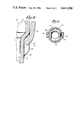
- FIG. 1 is a side elevational view, greatly enlarged, of the drawn sheet metal connector body portion of the receptacle having a size comparable to that of the stem in a small watch, with portions broken away and shown in vertical section to reveal interior details. The location of the printed circuit board with respect to the body portion is illustrated by the broken lines.
- FIG. 2 is a side elevational view of the connector body portion, viewed at an angle of 90° with respect to the viewing of FIG. 1.
- FIG. 3 is a top plan view of the complete connector receptacle.
- FIG. 4 is a side elevational view of the complete connector receptacle with portions broken away and shown in vertical section to reveal interior details. The sectioning is taken on the line 4--4 of FIG. 3.
- FIG. 5 is a top plan view of the connector receptacle body of FIG. 1.
- FIG. 6 is a top plan view similar to that of FIG. 5 but showing the spring retainer fingers of the body portion extending laterally, prior to their being folded downward as in FIG. 1.
- FIG. 7 is a perspective view of the spring contactor shell that is contained in the receptacle body.
- FIG. 8 is a fragmentary sectional view, greatly enlarged, of the right sectional portion of FIG. 1, and
- FIG. 9 is a horizontal sectional view, greatly enlarged, taken on the line 9--9 of FIG. 1.
- the connector receptacle of the invention comprises essentially a two-piece assembly, an outer tubular shell or cup 10 also hereinafter called a tubular metal member or body portion, which is adapted to loosely, slidably fit into an opening of a printed circuit board, and an inner spring contactor member or component 12 (illustrated also in FIG. 7) which is formed separately from the body portion 10 and assembled to it at a later time.
- the spring contactor shell 12 comprises a tubular portion 14 having a flared mouth 16, and a plurality of resilient contact fingers 18 that converge from the portion 14 to a yet smaller, tubular formation 20.
- triangular slits 22 exist, such slits showing as straight line cuts 24 at the tubular formation 20.
- the contact fingers 18 are thus separate from each other and individually movable, being biased toward the center or axis of the shell to maintain the tubular portion 20 mostly in a closed condition.
- the contactor shell 12 can fit snugly within the body portion 10 of the receptacle shell or cup at its upper part and is retained therein by a pair of lugs or tabs 26 integral with a flared mouth 28 of the body portion 10, as clearly seen in FIG. 4.
- the contactor shell 12 is so mounted that the spring fingers 18 thereof can shift laterally or radially outward an extent to accommodate the larger diameter of a cooperable contact pin or pin terminal which is inserted in the receptacle through the mouth portion 28.
- the receptacle body portion 10 is in the form of a deep drawn tubular metal member or shell having in addition to the flared mouth 28, a main tubular body portion 30 which is mostly of smooth cylindrical outer configuration and which is joined to the small diameter of the flare 28, and a lower extremity portion or tip 32 of still smaller diameter, which joins the main body portion 30 and forms an exterior intermediate annular beveled shoulder 34 at the joint.
- the body portion 10 is referred to as having a first section (the portion 32), a second section (the portion 30), and a third section (the flare portion 28).
- the retainer tabs 26 are also blanked out, as will be understood.
- the exterior diameter of the main body portion 30 of the receptacle 10 is chosen to have an easy sliding fit in openings provided in a printed circuit board 36, such as that shown in broken outline in FIG. 1.
- the receptacle body portion 10 is provided with integral external resilient spring retainer means in the form of fingers 38, two such fingers being illustrated in the drawings and being disposed on opposite sides of the main body portion 30 and extending lengthwise thereof.
- the spring fingers 38 can be blanked or formed at the same time that the tabs 26 are blanked out, and such forming of the spring fingers 38 preferably occurs after the deep drawing of the body portions 30, 32 has been effected.
- FIG. 6 illustrates the blanking or formation of the spring fingers 38 initially.
- the fingers are given a flattened N-configuration forming a bowed section, with a pair of reverse bends 42, 44.
- the free end portions of the spring fingers 38 have narrowed angular offsets 46 which are adapted to extend closely adjacent the external annular shoulder 34 of the shell 10 after the spring fingers have been folded downward to their ultimate positions as shown in FIG. 1 wherein such offsets are inwardly-turned when the fingers extend along and exterior to the smooth outside cylindrical surface of the main body portion 30 of the shell.
- the intermediate annular shoulder 34 is provided with recess means, by being displaced so as to have a pair of oppositely disposed, external semi-circular recesses or indentations 48 in which the narrowed angular offset portions 46 of the fingers are nested and terminate whereby they will not present any shoulder surfaces, other than sloping, beyond the theoretical extensions of the shoulder, which might interfere with the easy insertion of the shell body 10 in the opening of the circuit board. It can be readily understood, when viewing FIG.
- each recess 48 are flush with and continuations of the exterior surface of the reduced-diameter tip portion 32 of the shell, and the walls of the shoulder 34 on opposite sides of its recess 48 are higher than the extremities 46 of reduced width of the fingers 38.
- the recesses are formed as indentations in the shell, whereby the recesses have concave outer walls and convex inner walls at the locations of the recesses.
- the inner walls formed by the indentations protrude inwardly into the bore of the shell at the locations of the recesses.
- the wall thicknesses of the shell at its main cylindrical body portion, its recesses, and its reduced-diameter tip portion are seen to be essentially uniform or equal.
- the bottom tips of the fingers can engage the exposed surfaces of the recesses 48 to provide a backup action of the fingers, and engagement can also occur where the bends 42 of the fingers exist, between such bends and the exterior of the shell body 10.
- the flattened N-configuration of the fingers 38 represent the bowed flexing portions thereof, these being disposed wholly outside of the recesses 48 and extending along and outside of the smooth exterior cylindrical surface of the main body portion 30 of the shell.
- the N-configuration also provides external depressions which tend to accommodate the edges of the opening into which the receptacle is inserted, thereby providing a desirable detent action.
- flexing of the fingers 38 which occurs when the receptacle is inserted in the opening of the circuit board 36 results in a slight longitudinal movement of the finger tips 46 in the recesses 48.
- the flare 28 constitutes an external shoulder which provides a positive stop for engagement with the circuit board during the insertion of the receptacle, and the resilient spring fingers 38 engage the circuit board and securely retain the receptacle in the desired operative position without danger of solder being brought into the receptacle to interfere with the necessary spring contact action.
- the receptacle can be fabricated to very close tolerances in an economical manner whereby it will meet the most exacting requirements and specifications, while at the same time it represents an extremely economical construction.
Landscapes
- Coupling Device And Connection With Printed Circuit (AREA)
Abstract
Description
Claims (11)
Priority Applications (1)
| Application Number | Priority Date | Filing Date | Title |
|---|---|---|---|
| US06/818,906 US4614388A (en) | 1984-12-13 | 1986-01-15 | Connector socket for printed circuit boards |
Applications Claiming Priority (2)
| Application Number | Priority Date | Filing Date | Title |
|---|---|---|---|
| US68113884A | 1984-12-13 | 1984-12-13 | |
| US06/818,906 US4614388A (en) | 1984-12-13 | 1986-01-15 | Connector socket for printed circuit boards |
Related Parent Applications (1)
| Application Number | Title | Priority Date | Filing Date |
|---|---|---|---|
| US68113884A Continuation | 1984-12-13 | 1984-12-13 |
Publications (1)
| Publication Number | Publication Date |
|---|---|
| US4614388A true US4614388A (en) | 1986-09-30 |
Family
ID=27102596
Family Applications (1)
| Application Number | Title | Priority Date | Filing Date |
|---|---|---|---|
| US06/818,906 Expired - Fee Related US4614388A (en) | 1984-12-13 | 1986-01-15 | Connector socket for printed circuit boards |
Country Status (1)
| Country | Link |
|---|---|
| US (1) | US4614388A (en) |
Cited By (3)
| Publication number | Priority date | Publication date | Assignee | Title |
|---|---|---|---|---|
| US4902235A (en) * | 1987-07-31 | 1990-02-20 | Texas Instruments Incorporated | Socket, connection system and method of making |
| US5135403A (en) * | 1991-06-07 | 1992-08-04 | Amp Incorporated | Solderless spring socket for printed circuit board |
| US6340320B1 (en) * | 1998-12-18 | 2002-01-22 | Honda Tsushin Kogyo Co., Ltd. | Probe pin assembly, a method of making the same and a connector using the same |
Citations (2)
| Publication number | Priority date | Publication date | Assignee | Title |
|---|---|---|---|---|
| US2192587A (en) * | 1936-10-03 | 1940-03-05 | Trumbull Electric Mfg Co | Bus bar distribution system |
| US4415212A (en) * | 1981-09-21 | 1983-11-15 | Mark Eyelet & Stamping, Inc. | Connector receptacle for printed circuit boards |
-
1986
- 1986-01-15 US US06/818,906 patent/US4614388A/en not_active Expired - Fee Related
Patent Citations (2)
| Publication number | Priority date | Publication date | Assignee | Title |
|---|---|---|---|---|
| US2192587A (en) * | 1936-10-03 | 1940-03-05 | Trumbull Electric Mfg Co | Bus bar distribution system |
| US4415212A (en) * | 1981-09-21 | 1983-11-15 | Mark Eyelet & Stamping, Inc. | Connector receptacle for printed circuit boards |
Cited By (3)
| Publication number | Priority date | Publication date | Assignee | Title |
|---|---|---|---|---|
| US4902235A (en) * | 1987-07-31 | 1990-02-20 | Texas Instruments Incorporated | Socket, connection system and method of making |
| US5135403A (en) * | 1991-06-07 | 1992-08-04 | Amp Incorporated | Solderless spring socket for printed circuit board |
| US6340320B1 (en) * | 1998-12-18 | 2002-01-22 | Honda Tsushin Kogyo Co., Ltd. | Probe pin assembly, a method of making the same and a connector using the same |
Similar Documents
| Publication | Publication Date | Title |
|---|---|---|
| US5238411A (en) | Connector for printed circuit board | |
| US3550067A (en) | Electrical receptacle and terminal | |
| US3744005A (en) | Zero force type connector block | |
| US6290553B1 (en) | Female terminal | |
| US5480320A (en) | Electrical connection element | |
| US3951494A (en) | Electrical connector | |
| US4299436A (en) | Electrical connector | |
| US5449304A (en) | Electrical connector having improved contacts | |
| CA1203865A (en) | Rib cage terminal | |
| US3781770A (en) | Circuit board socket | |
| JPH0275174A (en) | Terminal for electric connector | |
| EP0618646A2 (en) | Lever-operated connector | |
| US5100338A (en) | Contact for circuit board socket | |
| JPH0794226A (en) | Electrical terminal | |
| IL33029A (en) | Miniature connector | |
| US4415212A (en) | Connector receptacle for printed circuit boards | |
| US3368188A (en) | Wire grip circuit board eyelet | |
| US2304808A (en) | Contact | |
| EP0718933A1 (en) | Bulb socket | |
| US4614388A (en) | Connector socket for printed circuit boards | |
| US4375309A (en) | Zero insertion force connector block | |
| US3950061A (en) | Socket for wedge base lamp | |
| US3414871A (en) | Electrical connector having a resilient tongue means carrying two detent flaps | |
| EP0140615A2 (en) | Electrical assembly and pin-receptacle for printed circuit board | |
| US4720274A (en) | Electrical connector assembly |
Legal Events
| Date | Code | Title | Description |
|---|---|---|---|
| FEPP | Fee payment procedure |
Free format text: PAYOR NUMBER ASSIGNED (ORIGINAL EVENT CODE: ASPN); ENTITY STATUS OF PATENT OWNER: LARGE ENTITY |
|
| FPAY | Fee payment |
Year of fee payment: 4 |
|
| FEPP | Fee payment procedure |
Free format text: PAYER NUMBER DE-ASSIGNED (ORIGINAL EVENT CODE: RMPN); ENTITY STATUS OF PATENT OWNER: LARGE ENTITY |
|
| FPAY | Fee payment |
Year of fee payment: 8 |
|
| AS | Assignment |
Owner name: CENTERBANK, CONNECTICUT Free format text: SECURITY INTEREST;ASSIGNOR:MEI ACQUISITION CORPORATION;REEL/FRAME:008194/0450 Effective date: 19960920 Owner name: AFFILIATED BUSINESS CREDIT CORPORATION, CONNECTICU Free format text: ASSIGNMENT OF ASSIGNORS INTEREST;ASSIGNOR:MEI ACQUISITION CORP.;REEL/FRAME:008222/0063 Effective date: 19960920 |
|
| REMI | Maintenance fee reminder mailed | ||
| LAPS | Lapse for failure to pay maintenance fees | ||
| FP | Lapsed due to failure to pay maintenance fee |
Effective date: 19980930 |
|
| STCH | Information on status: patent discontinuation |
Free format text: PATENT EXPIRED DUE TO NONPAYMENT OF MAINTENANCE FEES UNDER 37 CFR 1.362 |