US4614231A - Evaporators - Google Patents
Evaporators Download PDFInfo
- Publication number
- US4614231A US4614231A US06/774,867 US77486785A US4614231A US 4614231 A US4614231 A US 4614231A US 77486785 A US77486785 A US 77486785A US 4614231 A US4614231 A US 4614231A
- Authority
- US
- United States
- Prior art keywords
- dished
- sheet
- core assembly
- endmost
- evaporator core
- Prior art date
- Legal status (The legal status is an assumption and is not a legal conclusion. Google has not performed a legal analysis and makes no representation as to the accuracy of the status listed.)
- Expired - Lifetime
Links
- 239000012530 fluid Substances 0.000 claims description 6
- 238000005219 brazing Methods 0.000 claims description 3
- 230000013011 mating Effects 0.000 claims 1
- 238000003860 storage Methods 0.000 abstract description 6
- 230000000712 assembly Effects 0.000 abstract description 3
- 238000000429 assembly Methods 0.000 abstract description 3
- 238000004378 air conditioning Methods 0.000 abstract 1
- XAGFODPZIPBFFR-UHFFFAOYSA-N aluminium Chemical compound [Al] XAGFODPZIPBFFR-UHFFFAOYSA-N 0.000 description 2
- 229910052782 aluminium Inorganic materials 0.000 description 2
- 238000000034 method Methods 0.000 description 2
- 239000011324 bead Substances 0.000 description 1
- 238000010276 construction Methods 0.000 description 1
- 238000004519 manufacturing process Methods 0.000 description 1
- 239000003507 refrigerant Substances 0.000 description 1
- 230000002787 reinforcement Effects 0.000 description 1
- 238000007789 sealing Methods 0.000 description 1
Images
Classifications
-
- F—MECHANICAL ENGINEERING; LIGHTING; HEATING; WEAPONS; BLASTING
- F28—HEAT EXCHANGE IN GENERAL
- F28F—DETAILS OF HEAT-EXCHANGE AND HEAT-TRANSFER APPARATUS, OF GENERAL APPLICATION
- F28F9/00—Casings; Header boxes; Auxiliary supports for elements; Auxiliary members within casings
- F28F9/02—Header boxes; End plates
- F28F9/0246—Arrangements for connecting header boxes with flow lines
- F28F9/0256—Arrangements for coupling connectors with flow lines
-
- F—MECHANICAL ENGINEERING; LIGHTING; HEATING; WEAPONS; BLASTING
- F25—REFRIGERATION OR COOLING; COMBINED HEATING AND REFRIGERATION SYSTEMS; HEAT PUMP SYSTEMS; MANUFACTURE OR STORAGE OF ICE; LIQUEFACTION SOLIDIFICATION OF GASES
- F25B—REFRIGERATION MACHINES, PLANTS OR SYSTEMS; COMBINED HEATING AND REFRIGERATION SYSTEMS; HEAT PUMP SYSTEMS
- F25B39/00—Evaporators; Condensers
- F25B39/02—Evaporators
-
- F—MECHANICAL ENGINEERING; LIGHTING; HEATING; WEAPONS; BLASTING
- F28—HEAT EXCHANGE IN GENERAL
- F28D—HEAT-EXCHANGE APPARATUS, NOT PROVIDED FOR IN ANOTHER SUBCLASS, IN WHICH THE HEAT-EXCHANGE MEDIA DO NOT COME INTO DIRECT CONTACT
- F28D1/00—Heat-exchange apparatus having stationary conduit assemblies for one heat-exchange medium only, the media being in contact with different sides of the conduit wall, in which the other heat-exchange medium is a large body of fluid, e.g. domestic or motor car radiators
- F28D1/02—Heat-exchange apparatus having stationary conduit assemblies for one heat-exchange medium only, the media being in contact with different sides of the conduit wall, in which the other heat-exchange medium is a large body of fluid, e.g. domestic or motor car radiators with heat-exchange conduits immersed in the body of fluid
- F28D1/03—Heat-exchange apparatus having stationary conduit assemblies for one heat-exchange medium only, the media being in contact with different sides of the conduit wall, in which the other heat-exchange medium is a large body of fluid, e.g. domestic or motor car radiators with heat-exchange conduits immersed in the body of fluid with plate-like or laminated conduits
- F28D1/0308—Heat-exchange apparatus having stationary conduit assemblies for one heat-exchange medium only, the media being in contact with different sides of the conduit wall, in which the other heat-exchange medium is a large body of fluid, e.g. domestic or motor car radiators with heat-exchange conduits immersed in the body of fluid with plate-like or laminated conduits the conduits being formed by paired plates touching each other
- F28D1/0325—Heat-exchange apparatus having stationary conduit assemblies for one heat-exchange medium only, the media being in contact with different sides of the conduit wall, in which the other heat-exchange medium is a large body of fluid, e.g. domestic or motor car radiators with heat-exchange conduits immersed in the body of fluid with plate-like or laminated conduits the conduits being formed by paired plates touching each other the plates having lateral openings therein for circulation of the heat-exchange medium from one conduit to another
- F28D1/0333—Heat-exchange apparatus having stationary conduit assemblies for one heat-exchange medium only, the media being in contact with different sides of the conduit wall, in which the other heat-exchange medium is a large body of fluid, e.g. domestic or motor car radiators with heat-exchange conduits immersed in the body of fluid with plate-like or laminated conduits the conduits being formed by paired plates touching each other the plates having lateral openings therein for circulation of the heat-exchange medium from one conduit to another the plates having integrated connecting members
-
- F—MECHANICAL ENGINEERING; LIGHTING; HEATING; WEAPONS; BLASTING
- F28—HEAT EXCHANGE IN GENERAL
- F28F—DETAILS OF HEAT-EXCHANGE AND HEAT-TRANSFER APPARATUS, OF GENERAL APPLICATION
- F28F9/00—Casings; Header boxes; Auxiliary supports for elements; Auxiliary members within casings
- F28F9/02—Header boxes; End plates
- F28F9/0246—Arrangements for connecting header boxes with flow lines
Definitions
- This invention relates to evaporator cores for automotive air conditioners and the like.
- the evaporator cores in General Motors and Ford automobiles are made by brazing preformed aluminum sheets together in a sophisticated brazing operation, in which considerable tooling cost is involved in each unit.
- the attaching tubes in the inlet, outlet, and in some cases, the oil return tube, are brazed and/or welded to the core.
- the invention has, as its primary object, the provision of substantial improvements in the manufacture of service or replacement evaporators, for automotive air conditioners.
- Another object of the invention is to provide an evaporator of the character described, which is of compact assembly and has unrestricted rotational positioning of the attaching tubes.
- a further object of the invention is to provide an evaporator comprising a basic evaporator core, which uses a minimum number of components to arrive at many different stack heights and flow configurations, which can be assembled to a maximum number of pre-established physical and functional requirements.
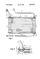
- FIG. 1 is an elevational view partly schematic, showing a single pass evaporator assembly, embodying the invention.
- FIG. 2 is a fragmentary cross-sectional view, on an enlarged scale, of the upper left portion of FIG. 1.
- FIG. 1 an evaporator core assembly having features of conventional construction, including a plurality of stacked evaporator cores 1, each formed of a pair of dished aluminum sheets.
- a typical core is shown comprising a pair of substantially identical core sheets 1a having a fluid passage 1b between them, the core sheets 1a being joined at their margins as is conventional.
- the core sheets 1a are dished at their ends, to provide the protruding dished portion 4 and the recessed dished portion 5, the sheets 1a being, as is conventional, preferably of the same shape, but reversely oriented as shown to provide an individual core.
- the dished portions 4, 5 are apertured, so as to provide a passageway 6 through the cores transversely of them, in the nature of a header, so that fluid will flow between headers at the ends of the cores through the fluid passage 1b.
- the sheets are brazed to each other at their margins to form the individual cores 1 and to provide a core assembly of stacked cores 1.
- conventional sinusoidal heat conducting fins 8 are provided to conduct heat transferred from the fluid within the core assembly to air passing in the spaces between the cores 1.
- a top terminal sheet 2 and a bottom terminal sheet 3 are provided to cover and hold the endmost fins 8.
- the terminal sheet 2 is over the endmost core 1 and has a portion of it spaced from and generally parallel to the endmost sheet 7 of the endmost core 1, the spaced portion of terminal sheet 2 being in laterally spaced relationship to the dished portion 5 of the endmost dished core sheet 1a.
- the core sheet 7, which cooperates with the endmost dished core sheet 1a has an apertured flat portion overlying the apertured recessed portion of the endmost dished core sheet 1a, and it is to the upper surface of the cooperating core sheet 7 of the endmost core 1 that the terminal sheet 2 is attached.
- the evaporator assembly further comprises an outlet tube 9, an inlet tube 10, and an oil return tube 11, which are normally brazed and/or welded to the core.
- a female joint fitting 12 is provided, having an axially extending portion which extends through a reinforcement plate 13 and is brazed to the latter.
- the fitting 12 also extends through the sheet 7, and into the passageway or channel 6 formed by the apertured dished portions 4 and 5 of the uppermost and next uppermost cores 1.
- the fitting 12 is internally threaded, as at 14, and has a conical interior surface 15 below this threaded portion.
- the outlet tube 9 has an angulated portion 9a, which extends into the passageway 6, and which is provided with an annular flange 16, which is seated on the conical surface 15 of the fitting 12.
- An "O" ring (not shown) may be interposed between the flange 16, and the conical surface 15, to provide improved sealing.
- the tube 9 is secured to the fitting 12 by means of a male swivel nut 17 having an hexagonal head and an externally threaded lower portion 18, which is threadedly and removably secured to the threads 14 of the fitting 12.
- the tube 9 is thus removably secured to the evaporator core assembly, while, at the same time, the tube may be rotated about the axis of the passageway or channel 6, thus positioning the tube at any desired angle to the evaporator core assembly.
- the tube 10 is similarly secured to the evaporator core assembly by means of a male swivel nut 19 and a fitting 20, which are similar, in all respects, to the nut 17 and fitting 12, so that the tube 10 is not only removably secured to the evaporator core assembly, but may be rotated about the axis of the passageway or channel 6 at the opposite end of the assembly core assembly.
- the passageway or channel 6 at the end below tube 9 is closed at the end by means of a closure 21.
- the tube 11 is secured to the evaporator core assembly by means of a male swivel nut 22 and a fitting 23, which are similar in all respects to the nut 17 and fitting 12, so that the tube 11 is not only removably secured to the evaporator core assembly, but may be rotated about the axis of the passageway or channel at the opposite end of the assembly, thus positioning the tube at any desired angle to the evaporator core assembly.
- a significant feature of the present invention resides in yhe dimensions of the assembly.
- the number of threads and specific details of the attaching nuts are such that the overall height from the top of the nut 17 to the end of the evaporator (sheet 2) is approximately equivalent to the normal bead of weld found on these assemblies. This is critical and necessary, because the space available in the molded evaporator housing precludes the use of anything having dimensions larger than these.
- the evaporator assembly in the drawing is not shown in its normal use position.
- the normal position has the tubes 10 and 11 attached to the bottom and the single tube 9 attached to the top of the evaporator.
- the plate 23 is plugged by means of a fitting, such as 22, except that it is not drilled to receive a tube.
Landscapes
- Engineering & Computer Science (AREA)
- Physics & Mathematics (AREA)
- Thermal Sciences (AREA)
- Mechanical Engineering (AREA)
- General Engineering & Computer Science (AREA)
- Heat-Exchange Devices With Radiators And Conduit Assemblies (AREA)
Abstract
Description
Claims (13)
Priority Applications (1)
| Application Number | Priority Date | Filing Date | Title |
|---|---|---|---|
| US06/774,867 US4614231A (en) | 1982-08-09 | 1985-09-11 | Evaporators |
Applications Claiming Priority (2)
| Application Number | Priority Date | Filing Date | Title |
|---|---|---|---|
| US40626082A | 1982-08-09 | 1982-08-09 | |
| US06/774,867 US4614231A (en) | 1982-08-09 | 1985-09-11 | Evaporators |
Related Parent Applications (1)
| Application Number | Title | Priority Date | Filing Date |
|---|---|---|---|
| US06626485 Continuation | 1984-07-03 |
Publications (1)
| Publication Number | Publication Date |
|---|---|
| US4614231A true US4614231A (en) | 1986-09-30 |
Family
ID=27019442
Family Applications (1)
| Application Number | Title | Priority Date | Filing Date |
|---|---|---|---|
| US06/774,867 Expired - Lifetime US4614231A (en) | 1982-08-09 | 1985-09-11 | Evaporators |
Country Status (1)
| Country | Link |
|---|---|
| US (1) | US4614231A (en) |
Cited By (19)
| Publication number | Priority date | Publication date | Assignee | Title |
|---|---|---|---|---|
| US4679410A (en) * | 1986-10-30 | 1987-07-14 | General Motors Corporation | Integral evaporator and accumulator for air conditioning system |
| US4815534A (en) * | 1987-09-21 | 1989-03-28 | Itt Standard, Itt Corporation | Plate type heat exchanger |
| US4829780A (en) * | 1988-01-28 | 1989-05-16 | Modine Manufacturing Company | Evaporator with improved condensate collection |
| US5121790A (en) * | 1986-12-19 | 1992-06-16 | Blackstone Sweden Ab | Heat exchanger |
| US5168721A (en) * | 1991-03-28 | 1992-12-08 | K-Whit Tools, Inc. | Refrigerant recovery device |
| US5186017A (en) * | 1990-09-10 | 1993-02-16 | K-Whit Tools, Inc. | Refrigerant recovery device |
| US5222369A (en) * | 1991-12-31 | 1993-06-29 | K-Whit Tools, Inc. | Refrigerant recovery device with vacuum operated check valve |
| US5231841A (en) * | 1991-12-19 | 1993-08-03 | Mcclelland Ralph A | Refrigerant charging system and control system therefor |
| US5269373A (en) * | 1990-06-20 | 1993-12-14 | Nissan Motor Co., Ltd. | Heat exchanger |
| US5390732A (en) * | 1994-02-14 | 1995-02-21 | Chrysler Corporation | Clamping apparatus and method for heat exchanger plates |
| US5513700A (en) * | 1994-07-29 | 1996-05-07 | Ford Motor Company | Automotive evaporator manifold |
| US5758506A (en) * | 1996-07-03 | 1998-06-02 | White Industries, Llc | Method and apparatus for servicing automotive refrigeration systems |
| US20040211550A1 (en) * | 2002-03-05 | 2004-10-28 | Finch Derek I | Fluid connectors for heat exchangers |
| US20140166137A1 (en) * | 2011-09-09 | 2014-06-19 | Kabushiki Kaisha Kobe Seiko Sho (Kobe Steel, Ltd.) | Flow passage structure and flow passage structure manufacturing method |
| EP2469193A3 (en) * | 2010-06-09 | 2014-10-15 | Thomas Geck | Regulating system, regulator heat exchanger, method for providing a secondary medium and method for retrofitting a residence |
| FR3050020A1 (en) * | 2016-04-06 | 2017-10-13 | Valeo Systemes Thermiques | THERMAL EXCHANGER AND METHOD OF MANUFACTURING A HEAT EXCHANGER |
| US20180320996A1 (en) * | 2017-05-05 | 2018-11-08 | Benteler Automobiltechnik Gmbh | Cooling arrangement, fluid collector for cooling arrangement, and method of producing a fluid collector |
| WO2024008251A2 (en) | 2022-07-05 | 2024-01-11 | Bruse Gmbh & Co. Kg | Method for controlling a hot water and heater feed |
| US12228354B2 (en) * | 2018-09-25 | 2025-02-18 | Valeo Systemes Thermiques | Adapter for a heat exchanger header |
Citations (14)
| Publication number | Priority date | Publication date | Assignee | Title |
|---|---|---|---|---|
| US1795055A (en) * | 1928-04-25 | 1931-03-03 | Charles Hartmann Company | Hot-air heater |
| US1810215A (en) * | 1927-03-31 | 1931-06-16 | Karmazin John | Header construction |
| US2190584A (en) * | 1931-11-28 | 1940-02-13 | Cherry Burrell Corp | Heat exchange device |
| US2211514A (en) * | 1937-08-30 | 1940-08-13 | Mojonnier Bros Co | Heat exchanger |
| US2257442A (en) * | 1940-05-21 | 1941-09-30 | Henry F Yula | Thermostatically controlled mixing device |
| US2599389A (en) * | 1949-10-17 | 1952-06-03 | Douglas Aircraft Co Inc | Hydraulic fitting |
| US2858112A (en) * | 1955-05-25 | 1958-10-28 | Gen Motors Corp | Heat exchanger |
| US3499484A (en) * | 1966-11-24 | 1970-03-10 | Gianluigi Lanzoni | Two-fluid heat exchanger |
| US3850234A (en) * | 1972-09-08 | 1974-11-26 | Delanair Ltd | Heat exchangers |
| US3976128A (en) * | 1975-06-12 | 1976-08-24 | Ford Motor Company | Plate and fin heat exchanger |
| US4011905A (en) * | 1975-12-18 | 1977-03-15 | Borg-Warner Corporation | Heat exchangers with integral surge tanks |
| US4034802A (en) * | 1974-08-07 | 1977-07-12 | Alois Schwarz | Radiator made of aluminum for central-heating plants |
| US4274482A (en) * | 1978-08-21 | 1981-06-23 | Nihon Radiator Co., Ltd. | Laminated evaporator |
| US4327802A (en) * | 1979-06-18 | 1982-05-04 | Borg-Warner Corporation | Multiple fluid heat exchanger |
-
1985
- 1985-09-11 US US06/774,867 patent/US4614231A/en not_active Expired - Lifetime
Patent Citations (14)
| Publication number | Priority date | Publication date | Assignee | Title |
|---|---|---|---|---|
| US1810215A (en) * | 1927-03-31 | 1931-06-16 | Karmazin John | Header construction |
| US1795055A (en) * | 1928-04-25 | 1931-03-03 | Charles Hartmann Company | Hot-air heater |
| US2190584A (en) * | 1931-11-28 | 1940-02-13 | Cherry Burrell Corp | Heat exchange device |
| US2211514A (en) * | 1937-08-30 | 1940-08-13 | Mojonnier Bros Co | Heat exchanger |
| US2257442A (en) * | 1940-05-21 | 1941-09-30 | Henry F Yula | Thermostatically controlled mixing device |
| US2599389A (en) * | 1949-10-17 | 1952-06-03 | Douglas Aircraft Co Inc | Hydraulic fitting |
| US2858112A (en) * | 1955-05-25 | 1958-10-28 | Gen Motors Corp | Heat exchanger |
| US3499484A (en) * | 1966-11-24 | 1970-03-10 | Gianluigi Lanzoni | Two-fluid heat exchanger |
| US3850234A (en) * | 1972-09-08 | 1974-11-26 | Delanair Ltd | Heat exchangers |
| US4034802A (en) * | 1974-08-07 | 1977-07-12 | Alois Schwarz | Radiator made of aluminum for central-heating plants |
| US3976128A (en) * | 1975-06-12 | 1976-08-24 | Ford Motor Company | Plate and fin heat exchanger |
| US4011905A (en) * | 1975-12-18 | 1977-03-15 | Borg-Warner Corporation | Heat exchangers with integral surge tanks |
| US4274482A (en) * | 1978-08-21 | 1981-06-23 | Nihon Radiator Co., Ltd. | Laminated evaporator |
| US4327802A (en) * | 1979-06-18 | 1982-05-04 | Borg-Warner Corporation | Multiple fluid heat exchanger |
Cited By (26)
| Publication number | Priority date | Publication date | Assignee | Title |
|---|---|---|---|---|
| US4679410A (en) * | 1986-10-30 | 1987-07-14 | General Motors Corporation | Integral evaporator and accumulator for air conditioning system |
| US5121790A (en) * | 1986-12-19 | 1992-06-16 | Blackstone Sweden Ab | Heat exchanger |
| US4815534A (en) * | 1987-09-21 | 1989-03-28 | Itt Standard, Itt Corporation | Plate type heat exchanger |
| USRE37040E1 (en) | 1988-01-28 | 2001-02-06 | Modine Manufacturing Company | Evaporator with improved condensate collection |
| US4829780A (en) * | 1988-01-28 | 1989-05-16 | Modine Manufacturing Company | Evaporator with improved condensate collection |
| US5269373A (en) * | 1990-06-20 | 1993-12-14 | Nissan Motor Co., Ltd. | Heat exchanger |
| US5186017A (en) * | 1990-09-10 | 1993-02-16 | K-Whit Tools, Inc. | Refrigerant recovery device |
| US5168721A (en) * | 1991-03-28 | 1992-12-08 | K-Whit Tools, Inc. | Refrigerant recovery device |
| US5335512A (en) * | 1991-03-28 | 1994-08-09 | K-Whit Tools, Inc. | Refrigerant recovery device |
| US5317903A (en) * | 1991-12-19 | 1994-06-07 | K-Whit Tools, Inc. | Refrigerant charging system controlled by charging pressure change rate |
| US5231841A (en) * | 1991-12-19 | 1993-08-03 | Mcclelland Ralph A | Refrigerant charging system and control system therefor |
| US5222369A (en) * | 1991-12-31 | 1993-06-29 | K-Whit Tools, Inc. | Refrigerant recovery device with vacuum operated check valve |
| US5390732A (en) * | 1994-02-14 | 1995-02-21 | Chrysler Corporation | Clamping apparatus and method for heat exchanger plates |
| US5513700A (en) * | 1994-07-29 | 1996-05-07 | Ford Motor Company | Automotive evaporator manifold |
| US5758506A (en) * | 1996-07-03 | 1998-06-02 | White Industries, Llc | Method and apparatus for servicing automotive refrigeration systems |
| US20040211550A1 (en) * | 2002-03-05 | 2004-10-28 | Finch Derek I | Fluid connectors for heat exchangers |
| US7000689B2 (en) * | 2002-03-05 | 2006-02-21 | Apv North America, Inc. | Fluid connectors for heat exchangers |
| EP2469193A3 (en) * | 2010-06-09 | 2014-10-15 | Thomas Geck | Regulating system, regulator heat exchanger, method for providing a secondary medium and method for retrofitting a residence |
| EP3139101A1 (en) * | 2010-06-09 | 2017-03-08 | Delta Systemtechnik GmbH | Regulating system, method for providing a secondary medium and method for retrofitting a residence |
| US20140166137A1 (en) * | 2011-09-09 | 2014-06-19 | Kabushiki Kaisha Kobe Seiko Sho (Kobe Steel, Ltd.) | Flow passage structure and flow passage structure manufacturing method |
| US9534722B2 (en) * | 2011-09-09 | 2017-01-03 | Kobe Steel, Ltd. | Flow passage structure and flow passage structure manufacturing method |
| FR3050020A1 (en) * | 2016-04-06 | 2017-10-13 | Valeo Systemes Thermiques | THERMAL EXCHANGER AND METHOD OF MANUFACTURING A HEAT EXCHANGER |
| US20180320996A1 (en) * | 2017-05-05 | 2018-11-08 | Benteler Automobiltechnik Gmbh | Cooling arrangement, fluid collector for cooling arrangement, and method of producing a fluid collector |
| US10619945B2 (en) * | 2017-05-05 | 2020-04-14 | Benteler Automobiltechnik Gmbh | Cooling arrangement, fluid collector for cooling arrangement, and method of producing a fluid collector |
| US12228354B2 (en) * | 2018-09-25 | 2025-02-18 | Valeo Systemes Thermiques | Adapter for a heat exchanger header |
| WO2024008251A2 (en) | 2022-07-05 | 2024-01-11 | Bruse Gmbh & Co. Kg | Method for controlling a hot water and heater feed |
Similar Documents
| Publication | Publication Date | Title |
|---|---|---|
| US4614231A (en) | Evaporators | |
| CA2128085C (en) | Modular cooler | |
| US4592414A (en) | Heat exchanger core construction utilizing a plate member adaptable for producing either a single or double pass flow arrangement | |
| US7658224B2 (en) | Flanged connection for heat exchanger | |
| US5325915A (en) | Modular cooler | |
| US5964280A (en) | Multiple fluid path plate heat exchanger | |
| US5924484A (en) | Plate heat exchanger | |
| US4258785A (en) | Heat exchanger interplate fitting | |
| US5179999A (en) | Circumferential flow heat exchanger | |
| US7237807B2 (en) | Pipe connecting structure for a heat exchanger | |
| EP0709643A2 (en) | Evaporator for a refrigerant | |
| US4745967A (en) | Heat exchanger, particularly a refrigerant evaporator | |
| US5664432A (en) | Vehicle air conditioning condenser | |
| CA1207318A (en) | Evaporators | |
| US20030159816A1 (en) | Heat exchanger apparatus with integrated supply/return tube | |
| US2229266A (en) | Heat exchanger | |
| US4429738A (en) | Heat exchanger construction | |
| GB2276937A (en) | Heat exchanger with feed tube having a bell shaped end | |
| EP0619468B1 (en) | Heat exchanger evaporator | |
| JPH09287887A (en) | Duplex heat exchanger | |
| US4544030A (en) | Shell nozzle | |
| JP3530989B2 (en) | Stacked heat exchanger | |
| US20250135844A1 (en) | Dual heat exchanger | |
| JPH0519714Y2 (en) | ||
| JPH0720522Y2 (en) | Heat exchanger |
Legal Events
| Date | Code | Title | Description |
|---|---|---|---|
| STCF | Information on status: patent grant |
Free format text: PATENTED CASE |
|
| FEPP | Fee payment procedure |
Free format text: PAYOR NUMBER ASSIGNED (ORIGINAL EVENT CODE: ASPN); ENTITY STATUS OF PATENT OWNER: LARGE ENTITY |
|
| FPAY | Fee payment |
Year of fee payment: 4 |
|
| AS | Assignment |
Owner name: M/E AUTOMOTIVE CORP, A CORP. OF DE, MISSOURI Free format text: ASSIGNMENT OF ASSIGNORS INTEREST.;ASSIGNOR:MURRAY CORPORATION, A CORP. OF ME;REEL/FRAME:005829/0832 Effective date: 19910131 |
|
| FPAY | Fee payment |
Year of fee payment: 8 |
|
| AS | Assignment |
Owner name: MOOG AUTOMOTIVE, INC., MISSOURI Free format text: MERGER, EFFECTIVE DECEMBER 31, 1993;ASSIGNOR:M/E AUTOMOTIVE CORP;REEL/FRAME:008639/0443 Effective date: 19970807 |
|
| AS | Assignment |
Owner name: MOOG AUTOMOTIVE PRODUCTS, INC., MISSOURI Free format text: CHANGE OF NAME;ASSIGNOR:MOOG AUTOMOTIVE, INC.;REEL/FRAME:008933/0083 Effective date: 19971217 |
|
| FPAY | Fee payment |
Year of fee payment: 12 |
|
| AS | Assignment |
Owner name: STANDARD MOTOR PRODUCTS, INC., NEW YORK Free format text: ASSIGNMENT OF ASSIGNORS INTEREST;ASSIGNOR:MOOG AUTOMOTIVE PRODUCTS, INC.;REEL/FRAME:009570/0960 Effective date: 19980328 |
|
| AS | Assignment |
Owner name: GENERAL ELECTRIC CAPITAL CORPORATION, CONNECTICUT Free format text: SECURITY INTEREST;ASSIGNOR:STANDARD MOTOR PRODUCTS, INC.;REEL/FRAME:013774/0052 Effective date: 20030207 |
|
| AS | Assignment |
Owner name: STANDARD MOTOR PRODUCTS, INC., NEW YORK Free format text: RELEASE OF PATENT SECURITY AGREEMENT;ASSIGNOR:GENERAL ELECTRIC CAPITAL CORPORATION;REEL/FRAME:037045/0749 Effective date: 20151028 |
|
| AS | Assignment |
Owner name: JPMORGAN CHASE BANK, N.A., AS ADMINISTRATIVE AGENT Free format text: SECURITY INTEREST;ASSIGNOR:STANDARD MOTOR PRODUCTS, INC.;REEL/FRAME:037059/0153 Effective date: 20151028 |
|
| AS | Assignment |
Owner name: STANDARD MOTOR PRODUCTS, INC., NEW YORK Free format text: RELEASE BY SECURED PARTY;ASSIGNOR:JPMORGAN CHASE BANK, N.A., AS ADMINISTRATIVE AGENT;REEL/FRAME:060316/0724 Effective date: 20220601 |