US4612469A - Speed governor - Google Patents
Speed governor Download PDFInfo
- Publication number
- US4612469A US4612469A US06/669,925 US66992584A US4612469A US 4612469 A US4612469 A US 4612469A US 66992584 A US66992584 A US 66992584A US 4612469 A US4612469 A US 4612469A
- Authority
- US
- United States
- Prior art keywords
- magnets
- speed governor
- casing
- magnet
- adjustment
- Prior art date
- Legal status (The legal status is an assumption and is not a legal conclusion. Google has not performed a legal analysis and makes no representation as to the accuracy of the status listed.)
- Expired - Fee Related
Links
- 238000005192 partition Methods 0.000 claims description 5
- 230000008878 coupling Effects 0.000 claims 1
- 238000010168 coupling process Methods 0.000 claims 1
- 238000005859 coupling reaction Methods 0.000 claims 1
- 238000010276 construction Methods 0.000 abstract description 2
- 230000004907 flux Effects 0.000 description 5
- 210000000078 claw Anatomy 0.000 description 2
- 230000003111 delayed effect Effects 0.000 description 2
- 230000004048 modification Effects 0.000 description 2
- 238000012986 modification Methods 0.000 description 2
- 230000002093 peripheral effect Effects 0.000 description 2
- 238000005299 abrasion Methods 0.000 description 1
- 230000001133 acceleration Effects 0.000 description 1
- 239000000853 adhesive Substances 0.000 description 1
- 230000001070 adhesive effect Effects 0.000 description 1
- 230000003247 decreasing effect Effects 0.000 description 1
- 230000000694 effects Effects 0.000 description 1
- 239000013013 elastic material Substances 0.000 description 1
- 238000010438 heat treatment Methods 0.000 description 1
- 239000000696 magnetic material Substances 0.000 description 1
- 239000000463 material Substances 0.000 description 1
- 238000000034 method Methods 0.000 description 1
- 239000002991 molded plastic Substances 0.000 description 1
- 230000000630 rising effect Effects 0.000 description 1
- 238000003466 welding Methods 0.000 description 1
Images


Classifications
-
- H—ELECTRICITY
- H02—GENERATION; CONVERSION OR DISTRIBUTION OF ELECTRIC POWER
- H02K—DYNAMO-ELECTRIC MACHINES
- H02K49/00—Dynamo-electric clutches; Dynamo-electric brakes
- H02K49/02—Dynamo-electric clutches; Dynamo-electric brakes of the asynchronous induction type
- H02K49/04—Dynamo-electric clutches; Dynamo-electric brakes of the asynchronous induction type of the eddy-current hysteresis type
- H02K49/046—Dynamo-electric clutches; Dynamo-electric brakes of the asynchronous induction type of the eddy-current hysteresis type with an axial airgap
-
- H—ELECTRICITY
- H02—GENERATION; CONVERSION OR DISTRIBUTION OF ELECTRIC POWER
- H02K—DYNAMO-ELECTRIC MACHINES
- H02K49/00—Dynamo-electric clutches; Dynamo-electric brakes
- H02K49/02—Dynamo-electric clutches; Dynamo-electric brakes of the asynchronous induction type
- H02K49/04—Dynamo-electric clutches; Dynamo-electric brakes of the asynchronous induction type of the eddy-current hysteresis type
- H02K49/043—Dynamo-electric clutches; Dynamo-electric brakes of the asynchronous induction type of the eddy-current hysteresis type with a radial airgap
Definitions
- the present invention relates to an improved speed governor of the eddy-current-brake-type for use in a delayed operation switch or the like.
- a delayed operation switch is, for example, provided with a speed governor (hereinafter referred to simply as a "governor”) in order to set a delay time.
- a speed governor hereinafter referred to simply as a "governor”
- This governor produces much operating noise and it is not possible to adjust the operating time thereof.
- Other eddy-current-brake-type governors have been proposed which do not produce large amounts of operating noise and which have a variable braking force adjustment or braking force per se.
- these governors have a drawback in that they are complex and the available braking force is relatively low.
- an object of the present invention is to provide a governor providing simultaneously a high braking force and easily adjustable operating braking force.
- a pair of annular magnets are disposed on opposite sides of a conductive plate.
- One of the two magnets is fixed to a casing, while the other is circumferentially rotatably supported with its rotational phase being made easily adjustable from the outside of the casing.
- the annular magnet has circumferentially alternating N and S poles. Only one pair of N and S poles may be used. Since the total magnetic flux in the conductive disk varies with the relative magnetic phase of the two magnets, the braking force varies correspondingly so that the operating delay time can easily be set within a predetermined range.
- an acceleration wheel train is constituted by a plurality of gears and the two shafts.
- a conductive disk is integrally fixed to a final one of the gears, and magnets are disposed on opposite sides of the conductive disk, one being fixed at the casing side and the other being held by an adjustment plate which is movable in the rotational direction.
- the gear train, the conductive disk, the adjustment plate, etc. are supported about the two shafts so as to provide a simple construction having the two shafts at the center thereof. Accordingly, the assembly operation is simplified.
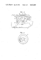
- FIG. 1 is a plan view showing a governor according to the present invention
- FIG. 2 is a longitudinal sectional view showing the governor of FIG. 1;
- FIG. 3 is a partially cut-away bottom view
- FIG. 4 is a plan view showing a ratchet portion
- FIGS. 5 and 6 are side views showing states of magnetic flux of the magnets.
- FIG. 7 is a longitudinal sectional view of a main portion of a modification of the governor of the invention.
- a governor 1 is incorporated in a casing 2 which is, for example, a molded plastic casing.
- the casing 2 is formed therein with a chamber 5 defined by a bottom and a top cover 3 and 4, which are respectively attached to the bottom and top of the casing 2.
- the casing 2 is integrally formed with a central partition 6 substantially at its center portion on the inside thereof so that the chamber 5 is divided into two portions, that is, upper and lower portions.
- the bottom cover 3, the top cover 4 and the central partition 6 support parallel shafts 7 and 8 within the chamber 5.
- the shaft 7 in this embodiment is located substantially at the center, and the shafts 7 and 8 alternately support an input side ratchet gear 10, a first gear 11, a composite-type second gear 12, a composite-type third gear 13, and a composite-type fourth gear 14, meshed between large and small gears and constituting an accelerator wheel train 9.
- the ratchet 16 is integrally formed at the base portion of the ratchet gear 10 of an elastically deformable material, and it meshes with ratchet teeth 17 formed on the inner circumferential side of the first gear 11 as shown in FIG. 4.
- Intermediate plates 18 and 19 are inserted between the first and third gears 11 and 13 and between the second and fourth gears 12 and 14, respectively, so as to prevent interference therebetween.
- THe intermediate plates 18 and 19 are fixed to the side surface of the casing 2 or the like.
- the shaft 7 rotatably supports a final gear 20 which meshes with large teeth of the fourth gear 14 at its intermediate portion.
- the final gear 20 is fitted and fixed at its boss 21 into a central hole of a conductive disk 22 and held in the state where it is prevented from rotating by an integral protrusion 23.
- the head of the protrusion 23 is flattened by heating.
- the portion where the shaft 7 supports the gear 20 is reduced in diameter, except at its upper and lower portions, so as to reduce the amount of frictional resistance.
- the conductive disk 22 is rotatably disposed between a pair of magnets 24 and 25 disposed opposite one another.
- the pair of magnets 24 and 25, which are each annularly shaped, are fixed within the chamber 5 in the casing 2 with the conductive disk 22 located therebetween.
- N and S poles are equidistantly formed at intervals of 60 degrees. The spacing and the number of the poles may be chosen as desired.
- One magnet 24 is fixed to the lower surface of the central partition portion 6 by a yoke 26, and the other magnet 25 is fixed to an upper surface of an adjustment plate 27.
- the adjustment plate 27 is pivotally supported on a bearing 28 in the bottom cover 3, and it grasps the magnet 25 by four claws 29 formed on the outer periphery thereof.
- An adjustment lever 30, integrally formed at an outer peripheral portion of the adjustment plate 27, projects outside through a slit 31 formed on the side surface of the casing 2.
- a positioning plate 32 is integrally formed in the rising portion of the casing 2.
- the positioning plate 32 formed of an elastic material, has a positioning projection 33 fitted into one of two positioning recesses 34a and 34b formed in the peripheral portions of the adjustment plate 27 so as to prevent the adjustment plate 27 from moving after positioning adjustment.
- the rotational angle of the adjustment plate 27 is set to about 25 degrees, corresponding to the central angle of the magnetic pole of the magnets 24 and 25, and therefore the opening angle with respect to the center defined by the two positioning recesses 34a and 34b is set also to about 25 degrees. It is a matter of course that this angle is suitably set according with the application at hand, and the position can be widely chosen by increasing the number of the positioning recesses.
- the ratchet gear 10 cannot mesh with the ratchet teeth 17 of the first gear 11 so that the ratchet gear 10 allows the gear 15 to rotate idly.
- the gear 15 rotates in the reverse direction, on the contrary, the ratchet 16 meshes with the ratchet teeth 17 so that the rotational speed of the outside gear 15 is increased by the accelerator wheel train 9, giving a high speed rotary motion to the conductive disk 22 through the final gear 20.
- the rotation of the conductive disk 22 is subjected to an eddy-current braking action by the magnetic flux of the pair of magnets 24 and 25.
- the outside gear 15 rotates only after a predetermined delay time. In this manner, a desired delay time can be ensured.
- the speed governing operation that is the braking force adjustment or braking force per se, can be adjusted by rotating the magnet 25 by the adjustment plate 27.
- substantially all the magnetic flux of the magnets 24 and 25 passes through the conductive disk 22 so that large eddy currents are generated in the conductive disk 22 to thereby generate a maximum braking force.
- the magnitude of the magnetic flux is decreased so as to make the braking force a minimum. Movement of the adjustment plate 27 to effect such movement of the magnets 24 and 25 can be easily performed externally by the adjustment lever 30.
- the angular interval between magnetic poles is 60 degrees, and the adjustment can be changed in steps of 25 degrees so that the delay time can be changed at a ratio of about 1:0.6.
- the positioning projection 33 is fitted into the positioning recess 34a or 34b after the adjustment so that the adjustment plate 27 does not rotate and is held stably even if it is subjected to a rotary force acting between the magnets 24 and 25.
- the shafts 7 and 8 are pressed into and fixed to the casing 2.
- the magnet 24, together with the yoke 26, is fixed to the side of the central partition portion 6 in the casing 2 by means of welding or riveting.
- the magnet 24 and the yoke 26 are fixed to each other by means of an adhesive or the like.
- the conductive disk 22 integrated with the final gear 20 is placed on the shaft 7 with the bottom cover 3 on the top.
- the magnet 25, together with the adjustment plate 27, is placed in the casing 2, and then the bottom cover 3 is fitted to the shafts 7 and 8.
- the bottom cover 3 is fixed to the casing 2 by means of fitting and engagement with a stopper claw, etc.
- the assembly of the magnets 24 and 25, the adjustment plate 27, etc. is complete.
- the third and fourth gears 13 and 14 are placed on the shafts 7 and 8, respectively, with the top cover 4 on the top.
- magnets 24 and 25 are arranged axially opposite to each other in the above-described embodiment, it is possible to arrange them concentrically with their diameters made different from each other as shown in FIG. 7.
- an accelerator wheel train is supported by shafts 7' and 8' fixed to a casing 2' in the same way as in the first-described embodiment.
- the fourth gear 14' meshes with a final gear 20', and a cup-like conductive plate 22' is fixed thereto.
- An annular magnet 24', integrally formed with a cylindrical yoke 26', is fixed to a bottom cover 3', and an annular magnet 25' is fixed to a cylindrical adjustment plate 27' made of a magnetic material, with the magnets 24' and 25' being concentrically arranged.
- the adjustment plate 27' is lightly pressed to fit it onto the stepped portion of the bottom cover 3'. It is possible to finely adjust the delay time by rotating the magnet 25' by an adjustment lever 30' integrally formed with the adjustment plate 27' so as to vary the relative phase of the poles of the magnets 25' with respect to the magnet 24'.
- a pair of annular magnets are arranged directly opposite each other, and a conductive disk is rotatably supported in the gap portion between the magnets.
Landscapes
- Engineering & Computer Science (AREA)
- Power Engineering (AREA)
- Dynamo-Electric Clutches, Dynamo-Electric Brakes (AREA)
Abstract
Description
Claims (16)
Applications Claiming Priority (4)
| Application Number | Priority Date | Filing Date | Title |
|---|---|---|---|
| JP58-174259[U] | 1983-11-10 | ||
| JP17425983U JPS6082984U (en) | 1983-11-10 | 1983-11-10 | Time-switchable delay-actuated switch |
| JP59-105067[U] | 1984-07-10 | ||
| JP10506784U JPS6119808U (en) | 1984-07-10 | 1984-07-10 | governor |
Publications (1)
| Publication Number | Publication Date |
|---|---|
| US4612469A true US4612469A (en) | 1986-09-16 |
Family
ID=26445415
Family Applications (1)
| Application Number | Title | Priority Date | Filing Date |
|---|---|---|---|
| US06/669,925 Expired - Fee Related US4612469A (en) | 1983-11-10 | 1984-11-09 | Speed governor |
Country Status (1)
| Country | Link |
|---|---|
| US (1) | US4612469A (en) |
Cited By (21)
| Publication number | Priority date | Publication date | Assignee | Title |
|---|---|---|---|---|
| US5125283A (en) * | 1990-08-10 | 1992-06-30 | K.K. Sankyo Seiki Seisakusho | Speed governor |
| WO2010104405A2 (en) | 2009-03-10 | 2010-09-16 | Holmes Solutions Limited | Improvements in and relating to braking mechanisms |
| US20130038070A1 (en) * | 2010-02-16 | 2013-02-14 | Kurt Andersen | Method for assembling part of a generator, generator and wind turbine |
| US20150167760A1 (en) * | 2012-06-15 | 2015-06-18 | Robert Bosch Gmbh | Machine Tool Deceleration Device |
| EP2561262A4 (en) * | 2010-04-23 | 2017-11-15 | Salte Tekniske AS | Device for damping of pendular movements and method of using same |
| US10020720B2 (en) | 2014-08-18 | 2018-07-10 | Eddy Current Limited Partnership | Latching devices |
| US10110089B2 (en) | 2014-08-18 | 2018-10-23 | Eddy Current Limited Partnership | Tuning of a kinematic relationship between members |
| US10263503B2 (en) * | 2014-04-11 | 2019-04-16 | Junqi DIAO | Permanent magnet speed governor with fixed magnetic gap |
| US10300397B2 (en) | 2013-12-16 | 2019-05-28 | Eddy Current Limited Partnership | Assembly to control or govern relative speed of movement between parts |
| US10374502B2 (en) * | 2014-12-05 | 2019-08-06 | Junqi DIAO | Permanent magnet speed governor having fixed magnetic gap |
| US10498210B2 (en) | 2014-08-18 | 2019-12-03 | Eddy Current Limited Partnership | Tuning of a kinematic relationship between members |
| US10532662B2 (en) | 2014-08-20 | 2020-01-14 | TruBlue LLC | Eddy current braking device for rotary systems |
| US10693360B2 (en) | 2014-12-04 | 2020-06-23 | Eddy Current Limited Partnership | Transmissions incorporating eddy current braking |
| US10774887B2 (en) | 2014-12-04 | 2020-09-15 | Eddy Current Limited Partnership | Latch activation between members |
| US10940339B2 (en) | 2014-12-04 | 2021-03-09 | Eddy Current Limited Partnership | Energy absorbing apparatus |
| US10953848B2 (en) | 2015-12-18 | 2021-03-23 | Eddy Current Limited Partnership | Variable behavior control mechanism for a motive system |
| US11050336B2 (en) | 2014-12-04 | 2021-06-29 | Eddy Current Limited Partnership | Methods of altering eddy current interactions |
| US11114930B2 (en) | 2014-12-04 | 2021-09-07 | Eddy Current Limited Partnership | Eddy current brake configurations |
| US12186596B2 (en) | 2019-09-20 | 2025-01-07 | TruBlue LLC | Lock-off descent control systems and devices |
| CN119891626A (en) * | 2025-03-27 | 2025-04-25 | 宁波弘翔电机有限公司 | Speed regulator device on automobile air conditioner motor |
| US12521578B2 (en) | 2020-03-18 | 2026-01-13 | TruBlue LLC | Line dispensing devices |
Citations (4)
| Publication number | Priority date | Publication date | Assignee | Title |
|---|---|---|---|---|
| US3700941A (en) * | 1971-02-03 | 1972-10-24 | John E Duncan | Adjustable hysteresis clutch and brake |
| US3831942A (en) * | 1973-02-13 | 1974-08-27 | Del Mar Eng Lab | Portable exercise machine |
| US4152617A (en) * | 1977-11-22 | 1979-05-01 | Dana Corporation | Selectively variable torque magnetic brake |
| US4224545A (en) * | 1977-08-27 | 1980-09-23 | Ferranti Limited | Speed control |
-
1984
- 1984-11-09 US US06/669,925 patent/US4612469A/en not_active Expired - Fee Related
Patent Citations (4)
| Publication number | Priority date | Publication date | Assignee | Title |
|---|---|---|---|---|
| US3700941A (en) * | 1971-02-03 | 1972-10-24 | John E Duncan | Adjustable hysteresis clutch and brake |
| US3831942A (en) * | 1973-02-13 | 1974-08-27 | Del Mar Eng Lab | Portable exercise machine |
| US4224545A (en) * | 1977-08-27 | 1980-09-23 | Ferranti Limited | Speed control |
| US4152617A (en) * | 1977-11-22 | 1979-05-01 | Dana Corporation | Selectively variable torque magnetic brake |
Cited By (44)
| Publication number | Priority date | Publication date | Assignee | Title |
|---|---|---|---|---|
| US5125283A (en) * | 1990-08-10 | 1992-06-30 | K.K. Sankyo Seiki Seisakusho | Speed governor |
| US8851235B2 (en) | 2009-03-10 | 2014-10-07 | Eddy Current Limited Partnership | Braking mechanisms |
| US10065054B2 (en) | 2009-03-10 | 2018-09-04 | Eddy Current Limited Partnership | Braking mechanisms |
| US10518115B2 (en) | 2009-03-10 | 2019-12-31 | Eddy Current Limited Partnership | Braking mechanisms |
| US11123580B2 (en) | 2009-03-10 | 2021-09-21 | Eddy Current Limited Partnership | Line dispensing device with Eddy current braking for use with climbing and evacuation |
| WO2010104405A2 (en) | 2009-03-10 | 2010-09-16 | Holmes Solutions Limited | Improvements in and relating to braking mechanisms |
| US20130038070A1 (en) * | 2010-02-16 | 2013-02-14 | Kurt Andersen | Method for assembling part of a generator, generator and wind turbine |
| EP2561262A4 (en) * | 2010-04-23 | 2017-11-15 | Salte Tekniske AS | Device for damping of pendular movements and method of using same |
| US9816572B2 (en) * | 2012-06-15 | 2017-11-14 | Robert Bosch Gmbh | Machine tool deceleration device |
| US20150167760A1 (en) * | 2012-06-15 | 2015-06-18 | Robert Bosch Gmbh | Machine Tool Deceleration Device |
| US11628373B2 (en) | 2013-12-16 | 2023-04-18 | Eddy Current Limited Partnership | Assembly to control or govern relative speed of movement between parts |
| US10300397B2 (en) | 2013-12-16 | 2019-05-28 | Eddy Current Limited Partnership | Assembly to control or govern relative speed of movement between parts |
| US11266917B2 (en) | 2013-12-16 | 2022-03-08 | Eddy Current Limited Partnership | Assembly to control or govern relative speed of movement between parts |
| US10603596B2 (en) | 2013-12-16 | 2020-03-31 | Eddy Current Limited Partnership | Assembly to control or govern relative speed of movement between parts |
| US10263503B2 (en) * | 2014-04-11 | 2019-04-16 | Junqi DIAO | Permanent magnet speed governor with fixed magnetic gap |
| US11632016B2 (en) | 2014-08-18 | 2023-04-18 | Eddy Current Limited Partnership | Tuning of a kinematic relationship between members |
| US11437903B2 (en) | 2014-08-18 | 2022-09-06 | Eddy Current Limited Partnership | Latching devices |
| US11735992B2 (en) | 2014-08-18 | 2023-08-22 | Eddy Current Limited Partnership | Tuning of a kinematic relationship between members |
| US10020720B2 (en) | 2014-08-18 | 2018-07-10 | Eddy Current Limited Partnership | Latching devices |
| US10110089B2 (en) | 2014-08-18 | 2018-10-23 | Eddy Current Limited Partnership | Tuning of a kinematic relationship between members |
| US10873242B2 (en) | 2014-08-18 | 2020-12-22 | Eddy Current Limited Partnership | Tuning of a kinematic relationship between members |
| US11515776B2 (en) | 2014-08-18 | 2022-11-29 | Eddy Current Limited Partnership | Tuning of a kinematic relationship between members |
| US10594200B2 (en) | 2014-08-18 | 2020-03-17 | Eddy Current Limited Partnership | Latching devices |
| US10971988B2 (en) | 2014-08-18 | 2021-04-06 | Eddy Current Limited Partnership | Latching devices |
| US11316404B2 (en) | 2014-08-18 | 2022-04-26 | Eddy Current Limited Partnership | Tuning of a kinematic relationship between members |
| US10498210B2 (en) | 2014-08-18 | 2019-12-03 | Eddy Current Limited Partnership | Tuning of a kinematic relationship between members |
| US10532662B2 (en) | 2014-08-20 | 2020-01-14 | TruBlue LLC | Eddy current braking device for rotary systems |
| US11992713B2 (en) | 2014-12-04 | 2024-05-28 | Eddy Current Limited Partnership | Energy absorbing apparatus |
| US11777391B2 (en) | 2014-12-04 | 2023-10-03 | Eddy Current Limited Partnership | Methods of altering eddy current interactions |
| US11009089B2 (en) | 2014-12-04 | 2021-05-18 | Eddy Current Limited Partnership | Latch activation between members |
| US12281681B2 (en) | 2014-12-04 | 2025-04-22 | Surewerx Usa, Inc. | Latch activation between members |
| US11499596B2 (en) | 2014-12-04 | 2022-11-15 | Eddy Current Limited Partnership | Latch activation between members |
| US10940339B2 (en) | 2014-12-04 | 2021-03-09 | Eddy Current Limited Partnership | Energy absorbing apparatus |
| US10774887B2 (en) | 2014-12-04 | 2020-09-15 | Eddy Current Limited Partnership | Latch activation between members |
| US10693360B2 (en) | 2014-12-04 | 2020-06-23 | Eddy Current Limited Partnership | Transmissions incorporating eddy current braking |
| US12009721B2 (en) | 2014-12-04 | 2024-06-11 | Eddy Current Limited Partnership | Eddy current brake configurations |
| US11114930B2 (en) | 2014-12-04 | 2021-09-07 | Eddy Current Limited Partnership | Eddy current brake configurations |
| US11050336B2 (en) | 2014-12-04 | 2021-06-29 | Eddy Current Limited Partnership | Methods of altering eddy current interactions |
| US10374502B2 (en) * | 2014-12-05 | 2019-08-06 | Junqi DIAO | Permanent magnet speed governor having fixed magnetic gap |
| US11878651B2 (en) | 2015-12-18 | 2024-01-23 | Eddy Current Limited Partnership | Variable behavior control mechanism for a motive system |
| US10953848B2 (en) | 2015-12-18 | 2021-03-23 | Eddy Current Limited Partnership | Variable behavior control mechanism for a motive system |
| US12186596B2 (en) | 2019-09-20 | 2025-01-07 | TruBlue LLC | Lock-off descent control systems and devices |
| US12521578B2 (en) | 2020-03-18 | 2026-01-13 | TruBlue LLC | Line dispensing devices |
| CN119891626A (en) * | 2025-03-27 | 2025-04-25 | 宁波弘翔电机有限公司 | Speed regulator device on automobile air conditioner motor |
Similar Documents
| Publication | Publication Date | Title |
|---|---|---|
| US4612469A (en) | Speed governor | |
| US3301091A (en) | Magnetic gearing arrangement | |
| US6812816B1 (en) | Rotary multi-position magnetic detent device | |
| US4455516A (en) | Brushless motor | |
| US3827232A (en) | Spring driven timer | |
| US4179943A (en) | Mechanical torque converter | |
| US3796898A (en) | Magnetic type transmission arrangement | |
| US2985778A (en) | Synchronous motor | |
| US4104859A (en) | Reversal preventing device of electric clock | |
| US2581965A (en) | Rate gyroscope | |
| JP2543156B2 (en) | Light-reflective rotary encoder | |
| US3443135A (en) | Rotary-magnet variable-voltage alternator,especially applicable to the power-transmission control of automobile vehicles | |
| JP2667209B2 (en) | Harmonic gear device using permanent magnet | |
| JPH0746066Y2 (en) | Governor | |
| US3496718A (en) | Clock movement with improved shaft bearing means facilitating assembly thereof | |
| US3198974A (en) | Ignition distributor | |
| US2656175A (en) | Inertia differentially modified governor | |
| US3746137A (en) | Multiple-torque slip clutch | |
| JPH0135580Y2 (en) | ||
| US4043206A (en) | Channel selecting shaft mounting arrangement for UHF tuners | |
| US4995488A (en) | Control device for a coupling means such as a clutch | |
| US3473058A (en) | Self-starting synchronous motor | |
| JPH0130879Y2 (en) | ||
| US2776523A (en) | Chromatic effect producing spinning toy | |
| US3585878A (en) | Variable speed drive mechanism for motion picture projectors |
Legal Events
| Date | Code | Title | Description |
|---|---|---|---|
| AS | Assignment |
Owner name: KABUSHIKI KAISHA SANKYO SEIKI SEISAKUSHO, NO. 5329 Free format text: ASSIGNMENT OF ASSIGNORS INTEREST.;ASSIGNOR:MURAMATSU, KENJI;REEL/FRAME:004553/0337 Effective date: 19841101 |
|
| FEPP | Fee payment procedure |
Free format text: PAYOR NUMBER ASSIGNED (ORIGINAL EVENT CODE: ASPN); ENTITY STATUS OF PATENT OWNER: LARGE ENTITY |
|
| FPAY | Fee payment |
Year of fee payment: 4 |
|
| FEPP | Fee payment procedure |
Free format text: PAYER NUMBER DE-ASSIGNED (ORIGINAL EVENT CODE: RMPN); ENTITY STATUS OF PATENT OWNER: LARGE ENTITY Free format text: PAYOR NUMBER ASSIGNED (ORIGINAL EVENT CODE: ASPN); ENTITY STATUS OF PATENT OWNER: LARGE ENTITY |
|
| FPAY | Fee payment |
Year of fee payment: 8 |
|
| REMI | Maintenance fee reminder mailed | ||
| LAPS | Lapse for failure to pay maintenance fees | ||
| FP | Lapsed due to failure to pay maintenance fee |
Effective date: 19980916 |
|
| STCH | Information on status: patent discontinuation |
Free format text: PATENT EXPIRED DUE TO NONPAYMENT OF MAINTENANCE FEES UNDER 37 CFR 1.362 |